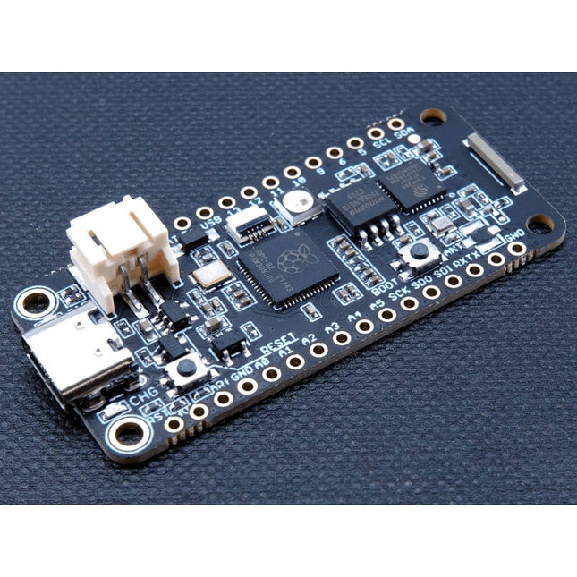
The Challenger RP2040 WiFi is a small embedded computer equipped with a WiFi module, in the popular Adafruit Feather form factor. It is based on an RP2040 microcontroller chip from the Raspberry Pi Foundation which is a dual-core Cortex-M0 that can run on a clock up to 133 MHz. The RP2040 is paired with a 8 MB high-speed flash capable of supplying data up to the max speed. The flash memory can be used both to store instructions for the microcontroller as well as data in a file system and having a file system available makes it easy to store data in a structured and easy to program approach. The device can be powered from a Lithium Polymer battery connected through a standard 2.0 mm connector on the side of the board. An internal battery charging circuit allows you to charge your battery safely and quickly. The device is shipped with a programming resistor that sets the charging current to 250 mA. This resistor can be exchanged by the user to either increase or decrease the charging current, depending on the battery that is being used. The WiFi section on this board is based on the Espressif ESP8285 chip which basically is a ESP8266 with 1 MB flash memory integrated onto the chip making it a complete WiFi only requiring very few external components. The ESP8285 is connected to the microcontroller using a UART channel and the operation is controlled using a set of standardized AT-commands. Specifications Microcontroller RP2040 from Raspberry Pi (133 MHz dual-core Cortex-M0) SPI One SPI channel configured I²C One I²C channel configured UART One UART channel configured (second UART is for the WiFi chip) Analog inputs 4 analog input channels WLAN controller ESP8285 from Espressif (160 MHz single-core Tensilica L106) Flash memory 8 MByte, 133 MHz SRAM memory 264 KByte (divided into 6 banks) USB 2.0 controller Up to 12 MBit/s full speed (integrated USB 1.1 PHY) JST Battery connector 2.0 mm pitch Onboard LiPo charger 250 mA standard charge current Onboard NeoPixel LED RGB LED Dimensions 51 x 23 x 3,2 mm Weight 9 g Downloads Datasheet Design files Product errata
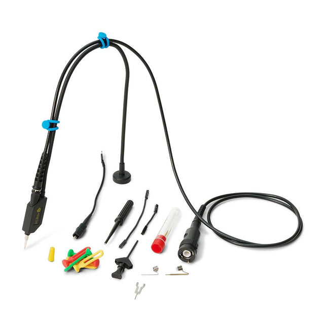
The SQ series of handsfree probes from Sensepeek have a lower point of gravity making them even more stable compared with the original SP series of handsfree probes. All probes in the SQ series are also insulated and can be used handheld as any traditional probe but their full potential is used when measuring handsfree.
The SQ series of oscilloscope probes also includes more ground options, have probe tip protection, longer cable and support for oscilloscopes with automatic scaling (10:1).
All the loved features of handsfree measurement, exchangeable fine pitch spring tipped test needle, color-coded cable holders and the minimalistic design is maintained to make traditional sized and handheld probes obsolete.
Both length and weight of the SQ probes are perfectly balanced to be used with PCBite PCB holders and base plate which is a must for handsfree function.
Features
Passive 10:1 probe with support for oscilloscopes with automatic scaling
Spring-loaded test needle for fine pitch measurements
Multiple ground options
Color coded cable holders
Probe tip protection
Insulated, can be used handheld
Improved probe holder for handsfree measurement when used with PCBite PCB holders
Included
1x SQ350 350 MHz probe with spring tipped test needle
1x SQ probe holder for handsfree measurement
1x Testhook with detachable cables (5 cm & 10 cm) for convenient ground connection
1x Alligator cable for convenient ground connection
1x Standard ground spring, for handheld measurements at rated bandwidth
1x Unique ground spring, for total handsfree measurements at rated bandwidth
1x Set of color coded cable holders (4 colors)
1x Probe tip protection
1x Extra test needle
Downloads
User Guide SQXX0 Rev1.1
YDLIDAR TG30 is a 360 degrees 2D LiDAR. Based on the principle of ToF, it is equipped with related optics, electricity, and algorithm design to achieve high-frequency and high-precision distance measurement. The mechanical structure rotates 360 degrees to continuously obtain the angle information and output the point cloud data of the scanning environment while ranging.
Features
IP65 protection level
360 degrees omnidirectional scanning and 5-12 Hz frequency
Ranging frequency up to 20 kHz
High accuracy, stable performance
Strong resistance to ambient light interference
Class I eye safety
Specifications
Range Frequency
20000 Hz
Scan Frequency
5-12 Hz
Range Distance
0.05-30 m
Scan Angle
360°
Angle resolution
0.09°-0.22°
Size Φ
75.8 x 34.7 mm
Applications
Robot navigation and obstacle avoidance
Industrial automation
Regional security
Smart transportation
Environmental scanning and 3D reconstruction
Digital multimedia interaction
Robot ROS teaching and research
Downloads
Datasheet
User manual
Development manual
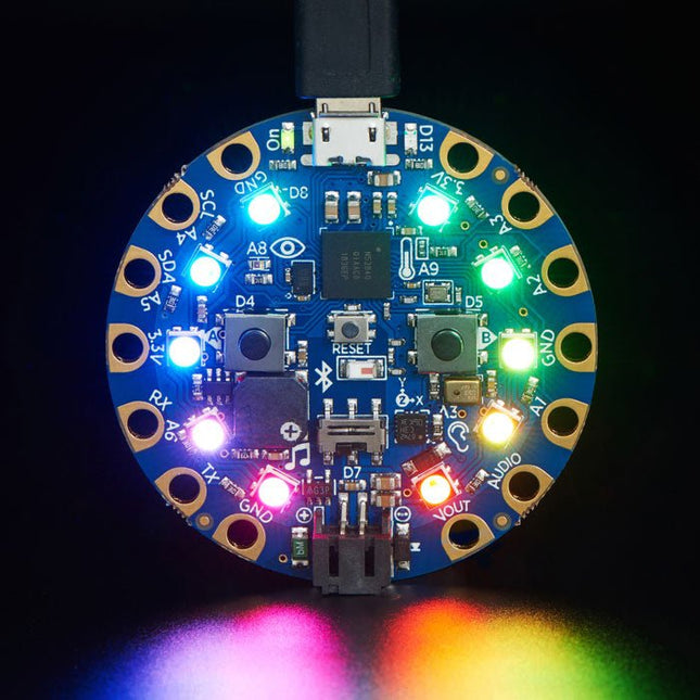
Circuit Playground Bluefruit is the third board in the Circuit Playground series, another step towards a perfect introduction to electronics and programming. Adafruit has taken the popular Circuit Playground Express and made it even better! Now the main chip is an nRF52840 microcontroller which is not only more powerful, but also comes with Bluetooth Low Energy support for wireless connectivity. The board is round and has alligator-clip pads around it so you don't have to solder or sew to make it work. You can power it from USB, a AAA battery pack, or with a Lipoly battery (for advanced users). Circuit Playground Bluefruit has built-in USB support. Built in USB means you plug it in to program it and it just shows up, no special cable or adapter required. Just program your code into the board then take it on the go! Features 1x nRF52840 Cortex M4 processor with Bluetooth Low Energy support 10x mini NeoPixels, each one can display any color 1x Motion sensor (LIS3DH triple-axis accelerometer with tap detection, free-fall detection) 1x Temperature sensor (thermistor) 1x Light sensor (phototransistor). Can also act as a color sensor and pulse sensor. 1x Sound sensor (MEMS microphone) 1x Mini speaker with class D amplifier (7.5 mm magnetic speaker/buzzer) 2x Push buttons, labeled A and B 1x Slide switch 8x alligator-clip friendly input/output pins Includes I²C, UART, 6 pins that can do analog inputs, multiple PWM outputs Green 'ON' LED so you know its powered Red '#13' LED for basic blinking Reset button 2 MB of SPI Flash storage, used primarily with CircuitPython to store code and libraries. MicroUSB port for programming and debugging USB port can act like serial port, keyboard, mouse, joystick or MIDI! Specifications Outer Diameter: ~50.6 mm / ~2.0' Weight: 8.9 g
The Sensirion SGP30 is a digital multi-pixel gas sensor that can easily integrate with air purifiers, demand-controlled ventilation, and other IoT applications. Powered by Sensirion’s CMOSens®technology, it integrates a complete sensor system on a single chip featuring a digital I2C interface, a temperature-controlled micro hotplate, and two preprocessed indoor air quality signals. As the first metal-oxide gas sensor featuring multiple sensing elements on one chip, the SGP30 provides more detailed information about air quality. Features Multi-pixel gas sensor for indoor air quality applications Outstanding long-term stability I2C interface with TVOC and CO2eq output signals Low power consumption Chip module tape and reel packaged, reflow solderable Specifications Weight: 9g Battery: Exclude Working Voltage: 3.3V/5V Output range: TVOC-0 ppb to 60000ppb / CO₂eq - 400 ppm to 60000 ppm Sampling rate: 1 Hz
Features Soil moisture sensor based on soil resistivity measurement Consists of two probes that allow the current to pass through the soil Easy to use and cost-effective Grove compatible interface( u-blox version) Specifications Dimensions: 60 x 20 x 6.35 mm
Weight: 10 g
Battery: Exclude
Operating voltage: 3.3 V ~ 5 V
Operating current: 35 mA
Sensor Output Value in dry soil: 0 ~ 300
Sensor Output Value in humid soil: 300 ~ 700
Sensor Output Value in water: 700 ~ 950
The flexibility of the Artemis module starts with SparkFun's Arduino core. You can program and use the Artemis module just like you would an Uno or any other Arduino. The time to first blink is just 5 minutes away! We built the core from the ground up, making it fast and as lightweight as possible.
Next is the module itself. Measuring 10 x 15 mm, the Artemis module has all the support circuitry you need to use the fantastic Ambiq Apollo3 processor in your next project. We're proud to say the SparkFun Artemis module is the first open-source hardware module with the design files freely and easily available. We've carefully designed the module so that implementing Artemis into your design can be done with low-cost 2-layer PCBs and 8mil trace/space.
Made in the USA at SparkFun's Boulder production line, the Artemis module is designed for consumer-grade products. This truly differentiates the Artemis from its Arduino brethren. Ready to scale your product? The Artemis will grow with you beyond the Uno footprint and Arduino IDE. Additionally, the Artemis has an advanced HAL (hardware abstraction layer), allowing users to push the modern Cortex-M4F architecture to its limit.
The SparkFun Artemis Module is fully FCC/IC/CE certified and is available in full tape and reel quantities. With 1M flash and 384k RAM, you'll have plenty of room for your code. The Artemis module runs at 48MHz with a 96MHz turbo mode available and with Bluetooth to boot!
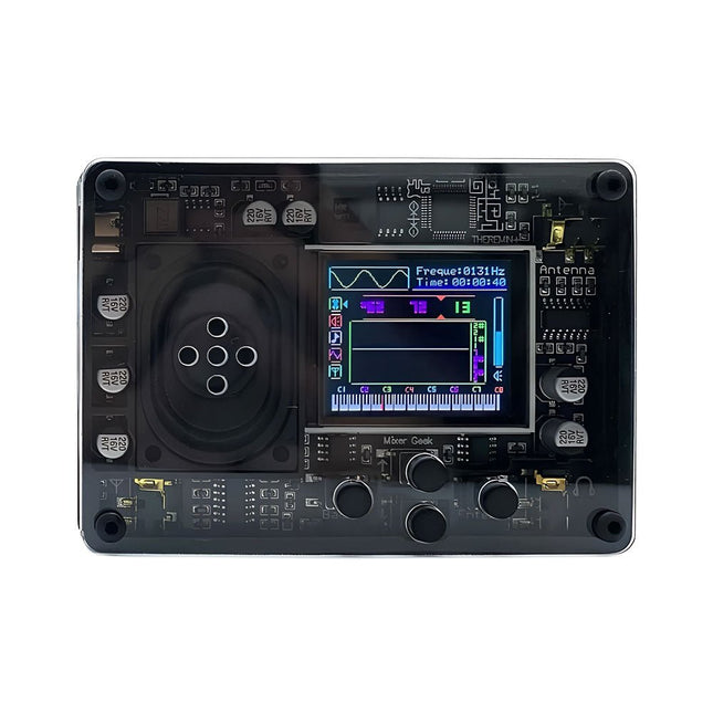
The Mixer Geek Theremin+ is a fun and innovative electronic musical instrument inspired by the classic Theremin. Unlike traditional instruments, the Theremin+ is played without physical contact, using hand movements in the air to control pitch and volume.
The Theremin+ offers an exciting and hands-on way to explore music and sound experimentation.
Features
Ready to use out of the box
Equipped with a loudspeaker and full-color screen
Intuitive button-based navigation and confirmation
Choose from over 70 tones
Multiple customizable function settings
Displays waveform, time, frequency, volume, and corresponding piano pitch (display can be turned off)
Powered via USB-C port; compatible with power banks
Compact design with removable telescopic antenna for easy storage
Connects to headphones, external speakers, or recording devices
Dimensions: 98 x 70 x 18 mm
Included
1x Theremin+ Musical Instrument
2x Antennas
1x USB-C cable
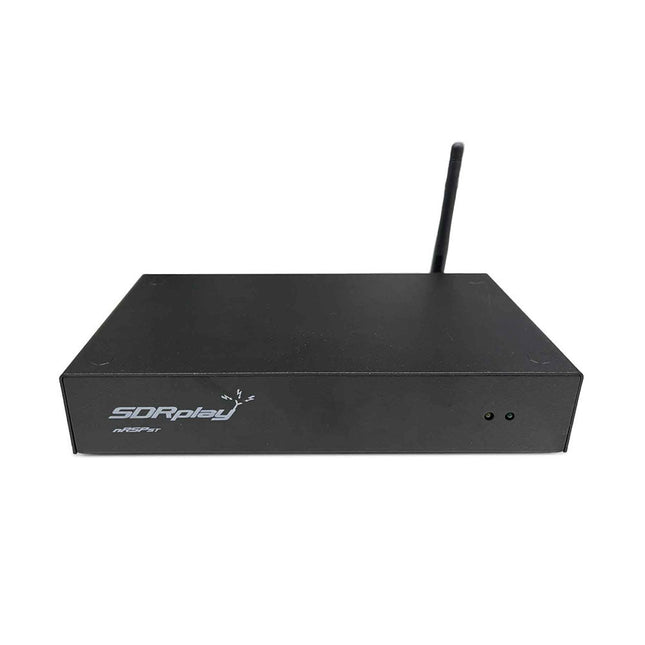
The nRSP-ST is a networked general coverage radio receiver for frequencies from 1 kHz to 2 GHz with up to 10 MHz of spectrum visibility. The nRSP-ST is your own personal remotely accessible SDR which can also be shared with a small number of trusted friends or colleagues.
The nRSP-ST addresses the needs of radio enthusiasts who want a 'plug-and-play' solution for remote reception. As well as achieving this, we have addressed typical internet bandwidth limitations with the creation of a novel IQ Lite mode, which efficiently delivers channels of IQ data. We are also introducing the ability to control and store IQ recordings at the remote location. The nRSP-ST is ideal for anyone wanting a wideband remote receiver without needing computer skills and hours of set-up time and ongoing maintenance at the remote location.
Features
"Plug and play" integrated, networked general coverage receiver:
Combines a receiver, a host computer and a whole lot more – all in one box!
Apply power and connect to the internet (Ethernet or Wi-Fi) and the nRSP-ST is automatically accessible from anywhere
Multi-platform SDRconnectTM software supports local operation or remote access on Windows, MacOS or Linux platforms
The nRSP-ST & SDRconnect are configurable for available network bandwidth:
In Full IQ mode, the nRSP-ST provides IQ data transfer of the visible spectrum bandwidth (e.g. for high-speed LAN or superfast internet connectivity)
In IQ Lite mode, the nRSP-ST provides IQ data of channels up to 192 kHz wide (e.g. for digital decoding by the client)
In Compact mode the nRSP-ST provides compressed audio (ideal for slower internet connections)
Supports multiple client connections with a simultaneous mixture of connection modes – an admin tool allows you to assign usernames and timeouts to trusted friends or colleagues.
All modes support visualization of up to 10 MHz spectrum bandwidth
Two remote connection options:
Use a remote SDRconnect client or
Use the built-in web-server for remote access from any web browsing capable device, including Android/iOS tablets and phones
The nRSP-ST offers the ability to record IQ and audio files to a NAS (network attached storage) device if available on the LAN.
The 14-bit ADC full featured wideband SDR receiver covers all frequencies from 1 kHz through VLF, LF, MW, HF, VHF, UHF and L-band to 2 GHz, with no gaps
Remotely monitor up to 10 MHz of spectrum at a time from a choice of 3 antennas
Flash upgradable for future feature enhancements
Included
1x nRSP-ST Receiver
1x WLAN antenna
1x Power supply
1x Manual
Downloads
Release notes
Software
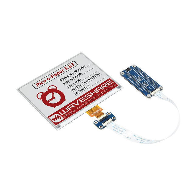
This 5.83-inch 3-color e-paper e-ink display module for Raspberry Pi Pico offers a resolution of 648 × 480 pixels, an SPI interface, low power consumption, wide viewing angle and a paper-like effect without electricity.
Features
No backlight, keeps displaying last content for a long time even when power down
Ultra low power consumption, basically power is only required for refreshing
SPI interface, requires minimal I/O pins
2x user buttons and 1x reset button for easy interacting
Comes with development resources and manual (Raspberry Pi Pico C/C++ and MicroPython examples)
Specifications
Operating voltage
3.3 V
Display color
Red, black, white
Resolution
648 × 480 pixels
Gray scale
2
Interface
3-wire SPI, 4-wire SPI
Viewing angle
>170°
Partial refresh time
N/A
Full refresh time
5s
Outline dimensions
125.4 × 99.5 mm
Display size
119.232 × 88.320 mm
Refresh power
26.4 mW (typ.)
Standby current
<0.01 uA (almost none)
Dot pitch
0.184 × 0.184 mm
Applications
Suitable For Price Tags
Asset/Equipment Tags
Shelf Labels
Conference Name Tag
Included
1x 5.83-inch e-Paper (B)
1x Pico-ePaper-Driver-Board
1x Standoff pack
Downloads
Wiki
This set contains 3 nozzles for Hot Air Rework Stations such as ZD-8922 or ZD-8968.
Included
1x Hot air nozzle 79-3911
1x Hot air nozzle 79-3912
1x Hot air nozzle 79-3913
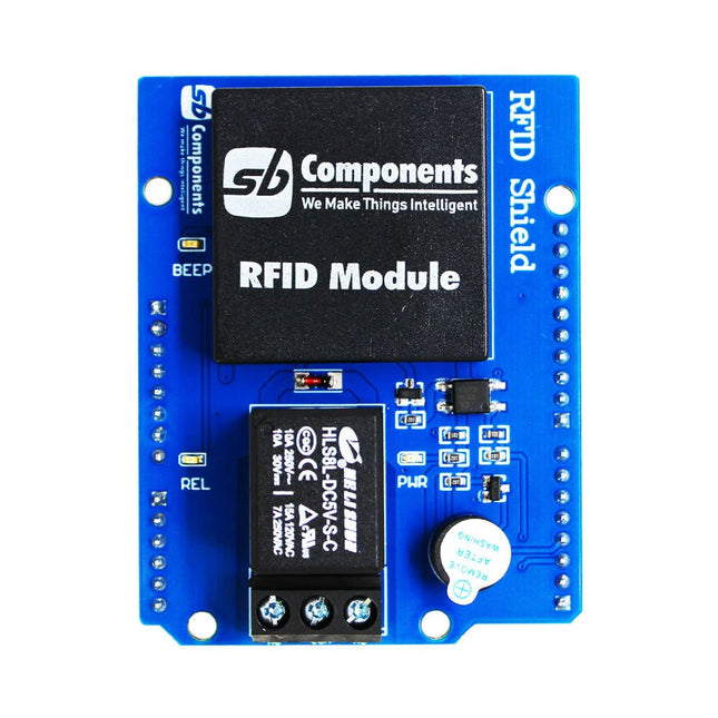
Designed with convenience and security in mind, the Ardi RFID Shield is based on the EM-18 module, operating at a frequency of 125 KHz. This shield allows you to easily integrate RFID (Radio Frequency Identification) technology into your projects, enabling seamless identification and access control systems.
Equipped with a powerful 1-channel optoisolated relay, the Ardi RFID Shield offers a reliable switching solution with a maximum DC rating of 30 V and 10 A, as well as an AC rating of 250 V and 7 A. Whether you need to control lights, motors, or other high-power devices, this shield provides the necessary functionality.
Additionally, the Ardi RFID Shield features an onboard buzzer that can be utilized for audio feedback, allowing for enhanced user interaction and system feedback. With the onboard 2-indication LEDs, you can easily monitor the status of RFID card detection, power supply, and relay activation, providing clear visual cues for your project's operation.
Compatibility is key, and the Ardi RFID Shield ensures seamless integration with the Arduino Uno platform. Paired with a read-only RFID module, this shield opens up a world of possibilities for applications such as access control systems, attendance tracking, inventory management, and more.
Features
Onboard 125 kHz EM18 RFID small, compact module
Onboard High-quality relays Relay with Screw terminal and NO/NC interfaces
Shield compatible with both 3.3 V and 5 V MCU
Onboard 3 LEDs power, relay ON/OFF State and RFID Scan status
Multi-tone Buzzer onboard for Audio alerts
Mounts directly onto ArdiPi, Ardi32 or other Arduino compatible boards
Specifications
RFID operating Frequency: 125 kHz
Reading distance: 10 cm, depending on TAG
Integrated Antenna
Relay Max Switching Voltage: 250 V AC/30 V DC
Relay Max Switching Current: 7 A/10 A
The SparkFun RP2040 mikroBUS Development Board is a low-cost, high performance platform with flexible digital interfaces featuring the Raspberry Pi Foundation's RP2040 microcontroller. Besides the Thing Plus or Feather PTH pin layout, the board also includes a microSD card slot, 16 MB (128 Mbit) flash memory, a JST single cell battery connector (with a charging circuit and fuel gauge sensor), an addressable WS2812 RGB LED, JTAG PTH pins, four (4-40 screw) mounting holes, our signature Qwiic connectors, and a mikroBUS socket. The mikroBUS standard was developed by MikroElektronika. Similar to Qwiic and MicroMod interfaces, the mikroBUS socket provides a standardized connection for add-on Click boards to be attached to a development board and is comprised of a pair of 8-pin female headers with a standardized pin configuration. The pins consist of three groups of communications pins (SPI, UART and I²C), six additional pins (PWM, Interrupt, Analog input, Reset and Chip select), and two power groups (3.3 V and 5 V). The RP2040 is supported with both C/C++ and MicroPython cross-platform development environments, including easy access to runtime debugging. It has UF2 boot and floating-point routines baked into the chip. While the chip has a large amount of internal RAM, the board includes an additional 16 MB of external QSPI flash memory to store program code. The RP2040 contains two ARM Cortex-M0+ processors (up to 133 MHz) and features: 264 kB of embedded SRAM in six banks 6 dedicated IO for SPI Flash (supporting XIP) 30 multifunction GPIO: Dedicated hardware for commonly used peripherals Programmable IO for extended peripheral support Four 12-bit ADC channels with internal temperature sensor (up to 0.5 MSa/s) USB 1.1 Host/Device functionality Features (SparkFun RP2040 mikroBUS Dev. Board) Raspberry Pi Foundation's RP2040 microcontroller 18 Multifunctional GPIO Pins Four available 12-bit ADC channels with internal temperature sensor (500kSa/s) Up to eight 2-channel PWM Up to two UARTs Up to two I²C buses Up to two SPI buses Thing Plus (or Feather) Pin Layout: 28 PTH Pins USB-C Connector: USB 1.1 Host/Device functionality 2-pin JST Connector for a LiPo Battery (not included): 500mA charging circuit 4-pin JST Qwiic Connector LEDs:
PWR - Red 3.3V power indicator
CHG - Yellow battery charging indicator
25 - Blue status/test LED (GPIO 25)
WS2812 - Addressable RGB LED (GPIO 08) Buttons: Boot Reset JTAG PTH Pins 16MB QSPI Flash Memory µSD Card Slot mikroBUS Socket Dimensions: 3.7' x 1.2' Four Mounting Holes: 4-40 screw compatible Downloads Schematic Eagle Files Board Dimensions Hookup Guide Qwiic Info Page GitHub Hardware Repository
The Tabloid/A3 size Magnetic Easel is a sturdy work-holding tool that provides an alternative method of positioning paper or other workpieces for use with the AxiDraw V3/A3 and AxiDraw SE/A3. A heavy-duty alternative to the regular A3 clip easel, it can be used with binder clips or the (included) positioning rulers, magnets, and magnetic spring clips. The base of the easel is a heavy-gauge sheet of magnetic steel. It has a powder-coat finish, lightly textured to help hold paper in place and light gray in color for visible contrast against most types of paper. Rubber bumpers on the bottom side (along with the substantial weight of the steel) ensure a no-slip grip on your work table. To help index your paper in a consistent and reproducible position, the easel includes two six-inch (15 cm) rulers that you can rest your paper up against. The rulers are easy to remove and reversible, with inch and centimeter markings on the two sides. They can also be removed completely if you like, leaving just a flat sheet of steel (with a few ruler-mounting holes in it). This A3 easel also includes a special set of paper holding clips and magnets: Two special spring clips with magnetic bases, plus six skinny magnets for holding down paper. The two special spring clips each have two curved tines that apply gentle pressure to your paper. They allow you to slide paper directly in and out, quickly and easily, without touching any magnets, clips, or tape. They have a long reach to be positioned behind the rulers, or elsewhere if you prefer. Magnetic bases allow you to position them where needed. Two of these spring clips provide just enough pressure to keep a sheet of paper steady while you write or draw on it. This set also includes six cylindrical magnets, 4 mm in diameter and 10 mm tall, which are easy to position and firmly hold paper. The tall aspect ratio makes them particularly easy to grasp (unlike disc magnets). Perhaps more importantly, they tend to yield and tip over if hit by an errant pen tip, rather than holding so fast as to damage your pen or move your paper. Overall dimensions: 18.12 x 12.72' (46.0 x 32.3 cm) Suitable for use with A3 and US Tabloid/Ledger paper sizes, envelopes, two sheets of Letter or A4 paper, or smaller sizes of paper.
Features Operate voltage: 3.3 V - 5 V Input current: 100mA Rated load: 5 A @ 250 VAC, 5 A @ 30 VDC Contact resistance: 50 mΩ @ 6 VDC 1 A Insulation resistance: 100 MΩ 10 ms Max. Operate time: 10 ms Max. Release time: 5 ms Max. Input interface: Digital Dimensions: 42 mm x 24 mm x 18.5 mm Included 1 x Grove Relay 1 x User Guide Downloads Grove Relay Schematics
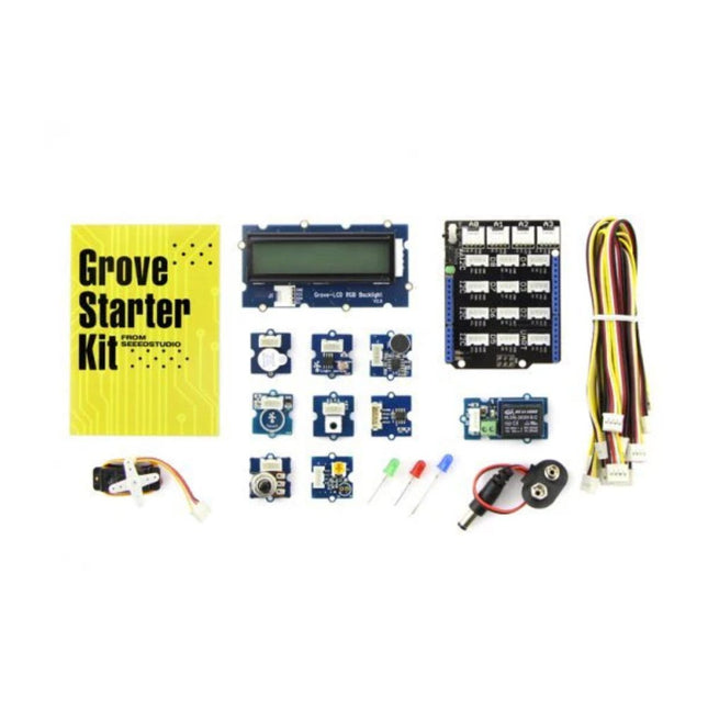
Grove is a modular electronic platform for quick prototyping. Every module has one function, such as touch sensing, creating audio effect and so on. Just plug the modules you need to the base shield, then you are ready to test your idea buds.
This Grove Starter Kit for Arduino is upgraded version of our Grove Starter Kit plus. Frequently used modules have been included in this kit to help you create your concept.
The changes
Optimize the internal slot structure, using technology to make our products inside plastic boxes more regularized, more protective.
Upgrade Instructions for creative poster form, more streamlined and intuitive description for each Grove-Sensor.
Grove-LED increased from three separate PCBA into a. But will still provide three different colors of LED light bulbs for you.
To consider the overall playability of the product experience, we optimized the two Grove-Sensors. Grove-Sound Sensor upgrade to V1.2; Grove-Temperature Sensor upgrade to the new SMD V1.1.
Data line upgrade from 24AWG Grove Cable is 26 AWG Grove Cable, wire length is adjusted to the length of 200mm unified model, the number was adjusted to 10.
Screen perfect upgrade for the Grove-LCD RGB Backlight, color screen makes further enhanced playability experience.
Included
1x Base Shield
1x Grove LCD RGB Backlight
1x Grove Smart Relay
1x Grove Buzzer
1x Grove Sound Sensor
1x Grove Touch Sensor
1x Grove Rotary Angle Sensor
1x Grove Temperature Sensor
1x Grove LED
1x Grove Light Sensor
1x Grove Button
1x DIP LED Blue-Blue
1x DIP LED Green-Green
1x DIP LED Red-Red
1x Mini Servo
10x Grove Cables
1x 9 V to Barrel Jack Adapter
1x Grove starter kit Manual
1x Green Plastic Box
Downloads
Schematic (PDF)
Schematic (Eagle)
Grove Button Source File
Grove LED Source File
Grove Buzzer Source File
Grove Rotary Angle Sensor Source File
Grove Relay Source File
Base Shield Source File
Grove Sound Sensor Source File
Grove Buzzer Source File
The Pimoroni Explorer Starter Kit is an electronic adventure playground for physical computing based on the RP2350 chip. It includes a 2.8-inch LCD screen, a speaker, a mini breadboard and much more. It's ideal for tinkering, experiments, and building small prototypes.
Features
Mini breadboard for wiring up components
Servo headers
Analog inputs
Built-in speaker
Plenty of general purpose inputs/outputs
Connectors for attaching crocodile leads
Qw/ST connectors for attaching I²C breakouts
Specifications
Powered by RP2350B (Dual Arm Cortex-M33 running at up to 150 MHz with 520 KB of SRAM)
16 MB of QSPI flash supporting XiP
2.8" IPS LCD screen (320 x 240 pixels)
Driver IC: ST7789V
Luminance: 250 cd/m²
Active area: 43.2 x 57.5 mm
USB-C connector for programming and power
Mini breadboard
Piezo speaker
6x user-controllable switches
Reset and boot buttons
Easy access GPIO headers (6x GPIOs and 3x ADCs, plus 3.3 V power and grounds)
6x Crocodile clip terminals (3x ADCs, plus 3.3 V power and grounds)
4x 3-pin servo outputs
2x Qw/ST (Qwiic/STEMMA QT) connector
2-pin JST-PH connector for adding a battery
Lanyard slot!
Includes 2x desktop stand feet
Fully-assembled (no soldering required)
Programmable with C/C++ or MicroPython
Included
1x Pimoroni Explorer
1x Multi-Sensor Stick – a fancy new all-in-one super sensor suite for environmental, light and movement sensing
Selection of different colored LEDs to get blinky with (including red, yellow, green, blue, white and RGB)
1x Potentiometer (for analog amusements)
3x 12 mm switches with different coloured caps
2x Continuous rotation servos
2x 60 mm wheels for attaching to your servos
1x AAA battery holder (batteries not included)
1x Velcro to stick the battery holder to the back of Explorer
20x Pin to pin and 20x pin to socket jumper wires for making connections on your breadboard
1x Qw/ST cable to plug in the Multi-Sensor Stick
1x Silicon USB-C cable
Downloads
GitHub
Schematic
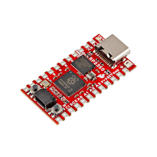
The SparkFun RP2350 Pro Micro provides a powerful development platform, built around the RP2350 microcontroller. This board uses the updated Pro Micro form factor. It includes a USB-C connector, Qwiic connector, WS2812B addressable RGB LED, Boot and Reset buttons, resettable PTC fuse, and PTH and castellated solder pads.
The RP2350 is a unique dual-core microcontroller with two ARM Cortex-M33 processors and two Hazard3 RISC-V processors, all running at up to 150 MHz! Now, this doesn't mean the RP2350 is a quad-core microcontroller. Instead, users can select which two processors to run on boot instead. You can run two processors of the same type or one of each. The RP2350 also features 520 kB SRAM in ten banks, a host of peripherals including two UARTs, two SPI and two I²C controllers, and a USB 1.1 controller for host and device support.
The Pro Micro also includes two expanded memory options: 16 MB of external Flash and 8 MB PSRAM connected to the RP2350's QSPI controller. The RP2350 Pro Micro works with C/C++ using the Pico SDK, MicroPython, and Arduino development environments.
Features
RP2350 Microcontroller
8 MB PSRAM
16 MB Flash
Supply Voltage
USB: 5 V
RAW: 5.3 V (max.)
Pro Micro Pinout
2x UART
1x SPI
10x GPIO (4 used for UART1 and UART0)
4x Analog
USB-C Connector
USB 1.1 Host/Device Support
Qwiic Connector
Buttons
Reset
Boot
LEDs
WS2812 Addressable RGB LED
Red Power LED
Dimensions: 33 x 17.8 mm
Downloads
Schematic
Eagle Files
Board Dimensions
Hookup Guide
RP2350 MicroPython Firmware (Beta 04)
SparkFun Pico SDK Library
Arduino Pico Arduino Core
Datasheet (RP2350)
Datasheet (APS6404L PSRAM)
RP2350 Product Brief
Raspberry Pi RP2350 Microcontroller Documentation
Qwiic Info Page
GitHub Repository
The FRDM-MCXN947 is a compact and versatile development board designed for rapid prototyping with MCX N94 and N54 microcontrollers. It features industry-standard headers for easy access to the MCU's I/Os, integrated open-standard serial interfaces, external flash memory, and an onboard MCU-Link debugger.
Specifications
Microcontroller
MCX-N947 Dual Arm Cortex-M33 cores @ 150 MHz each with optimized performance efficiency, up to 2 MB dual-bank flash with optional full ECC RAM, External flash
Accelerators: Neural Processing Unit, PowerQuad, Smart DMA, etc.
Memory Expansion
*DNP Micro SD card socket
Connectivity
Ethernet Phy and connector
HS USB-C connectors
SPI/I²C/UART connector (PMOD/mikroBUS, DNP)
WiFi connector (PMOD/mikroBUS, DNP)
CAN-FD transceiver
Debug
On-board MCU-Link debugger with CMSIS-DAP
JTAG/SWD connector
Sensor
P3T1755 I³C/I²C Temp Sensor, Touch Pad
Expansion Options
Arduino Header (with FRDM expansion rows)
FRDM Header
FlexIO/LCD Header
SmartDMA/Camera Header
Pmod *DNP
mikroBUS
User Interface
RGB user LED, plus Reset, ISP, Wakeup buttons
Included
1x FRDM-MCXN947 Development Board
1x USB-C Cable
1x Quick Start Guide
Downloads
Datasheet
Block diagram
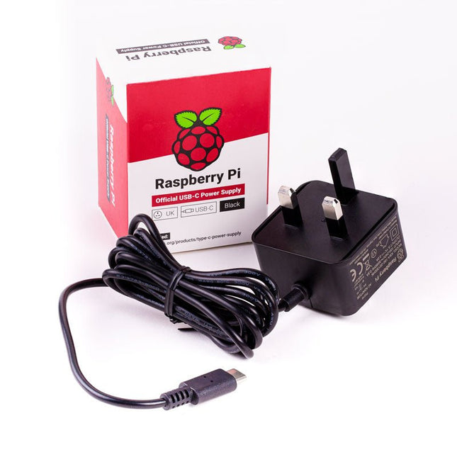
The Raspberry Pi USB-C power supply is designed specifically to power the latest Raspberry Pi 4 Model B computers.
The power supply features a USB-C cable and is available in four different models to suit different international power sockets, and in two colors.
Specifications
Output
Output voltage
+5.1 V DC
Minimum load current
0 A
Nominal load current
3.0 A
Maximum power
15.3 W
Load regulation
±5 %
Line regulation
±2 %
Ripple & noise
120 mVp-p
Rise time
100 ms maximum to regulation limits for DC outputs
Turn-on delay
3000 ms maximum at nominal input AC voltage and full load
Protection
Short circuit protectionOvercurrent protectionOver temperature protection
Efficiency
81% minimum (output current from 100%, 75%, 50%, 25%)72% minimum at 10% load
Output cable
1.5 m 18AWG
Output connector
USB Type-C
Input
Voltage range
100-240 VAC (rated)96-264 VAC (operating)
Frequency
50/60 Hz ±3 Hz
Current
0.5 A maximum
Power consumption (no load)
0.075 W maximum
Inrush current
No damage shall occur, and the input fuse shall not blow
Operating ambient temperature
0-40°C
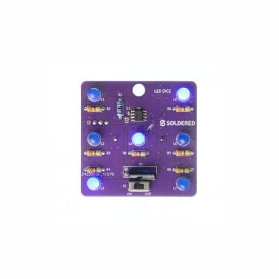
If you are looking for an easy way to get started with soldering or simply want to make a small portable gadget, this set is a great opportunity. "LED cube" is an educational set for learning the soldering skill, with which you get a small electronic game at the end. After you turn on and shake this board, certain leds will light up randomly and symbolize the number, as if a real die had been thrown.
It is based on the Attiny404 microcontroller, programmed in Arduino, and there is a battery on the back which makes this gadget portable. There is also a keychain so you can always carry your new game with you! Soldering is easy according to the markings on the board.
Included
1x PCB
1x ATtiny404 microcontroller
7x LEDs
7x Resistors (330 ohm)
1x Resistor (10 kohm)
1x Battery holder
1x CR2032 battery
1x Switch
1x Vibration sensor SW-18020P
1x Keychain ring
The Challenger RP2040 NFC is a small embedded computer, equipped with an advanced on-board NFC controller (NXP PN7150), in the popular Adafruit Feather form factor. It is based on an RP2040 microcontroller chip from the Raspberry Pi Foundation which is a dual-core Cortex-M0 that can run on a clock up to 133 MHz.
NFC
The PN7150 is a full featured NFC controller solution with integrated firmware and NCI interface designed for contactless communication at 13.56 MHz. It is fully compatible with NFC forum requirements and is greatly designed based on learnings from previous NXP NFC device generation. It is the ideal solution for rapidly integrating NFC technology in any application, especially small embedded systems reducing Bill of Material (BOM).
The integrated design with full NFC forum compliancy gives the user all the following features:
Embedded NFC firmware providing all NFC protocols as pre-integrated feature.
Direct connection to the main host or microcontroller, by I²C-bus physical and NCI protocol.
Ultra-low power consumption in polling loop mode.
Highly efficient integrated power management unit (PMU) allowing direct supply from a battery.
Specifications
Microcontroller
RP2040 from Raspberry Pi (133 MHz dual-core Cortex-M0)
SPI
One SPI channels configured
I²C
Two I²C channel configured (dedicated I²C for the PN7150)
UART
One UART channel configured
Analog inputs
4 analog input channels
NFC module
PN7150 from NXP
Flash memory
8 MB, 133 MHz
SRAM memory
264 KB (divided into 6 banks)
USB 2.0 controller
Up to 12 MBit/s full speed (integrated USB 1.1 PHY)
JST Battery connector
2.0 mm pitch
On board LiPo charger
450 mA standard charge current
Dimensions
51 x 23 x 3,2 mm
Weight
9 g
Note: Antenna is not included.
Downloads
Datasheet
Quick start example
The Arduino Nano 33 BLE Sense Rev2 with headers is Arduino’s 3.3 V AI enabled board in the smallest available form factor with a set of sensors that will allow you without any external hardware to start programming your next project, right away.
With the Arduino Nano 33 BLE Sense Rev2, you can:
Build wearable devices that using AI can recognize movements.
Build a room temperature monitoring device that can suggest or modify changes in the thermostat.
Build a gesture or voice recognition device using the microphone or the gesture sensor together with the AI capabilities of the board.
Differences between Rev1 and Rev2
Replacement of IMU from LSM9DS1 (9 axis) for a combination of two IMUs (BMI270 – 6 axis IMU and BMM150 – 3 axis IMU)
Replacement of temperature and humidity sensor from HTS221 for HS3003
Replacement of microphone from MP34DT05 to MP34DT06JTR
Replacement of power supply MPM3610 for MP2322
Addition of VUSB soldering jumper on the top side of the board
New test point for USB, SWDIO and SWCLK
Specifications
Microcontroller
nRF52840 (datasheet)
Operating Voltage
3.3 V
Input Voltage (limit)
21 V
DC Current per I/O Pin
15 mA
Clock Speed
64 MHz
CPU Flash Memory
1 MB (nRF52840)
SRAM
256 KB (nRF52840)
EEPROM
None
Digital Input / Output Pins
14
PWM Pins
All digital pins
UART
1
SPI
1
I²C
1
Analog Input Pins
8 (ADC 12 bit 200 k samples)
Analog Output Pins
Only through PWM (no DAC)
External Interrupts
All digital pins
LED_BUILTIN
13
USB
Native in the nRF52840 Processor
IMU
BMI270 (datasheet) and BMM150 (datasheet)
Microphone
MP34DT06JTR (datasheet)
Gesture, light, proximity, color
APDS9960 (datasheet)
Barometric pressure
LPS22HB (datasheet)
Temperature, humidity
HS3003 (datasheet)
Downloads
Datasheet
Schematics