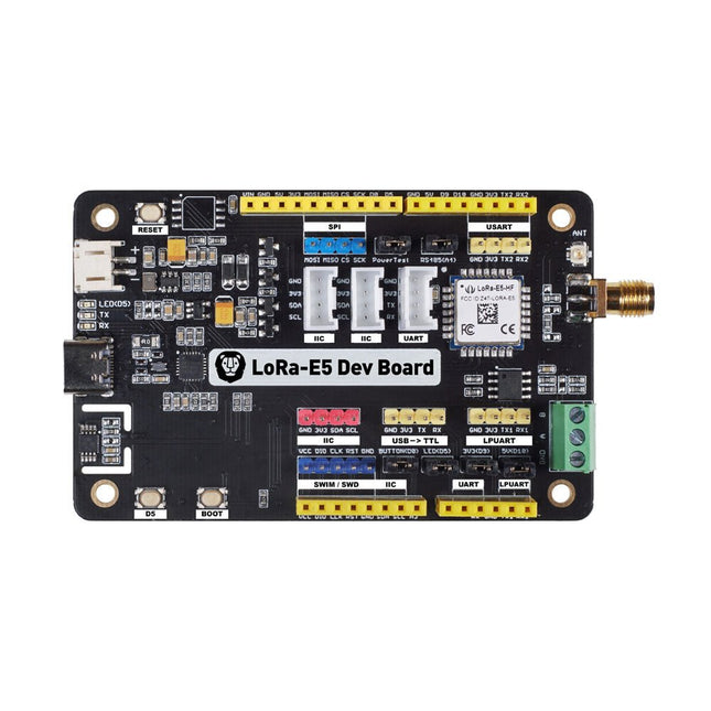
LoRa-E5 Development Kit is an easy-to-use compact development toolset for you to unlock the powerful performance of the LoRa-E5 STM32WLE5JC. It consists of a LoRa-E5 Dev Board, an antenna (EU868), a USB type C cable, and a 2-AA 3 V Battery Holder.
LoRa-E5 Dev Board embedded with LoRa-E5 STM32WLE5JC Module, which is the world-first combo of LoRa RF and MCU chip into one single tiny chip and is FCC and CE certified. It is powered by ARM Cortex-M4 core and Semtech SX126X LoRa chip, supports both LoRaWAN and LoRa protocol on the worldwide frequency and (G)FSK, BPSK, (G)MSK, and LoRa modulations.
The LoRa-E5 development board features a very long transmission range, extremely low power consumption and user-friendly interfaces.
LoRa-E5 Dev Board has a long-distance transmission range of LoRa-E5 up to 10 km in an open area. The sleep current of LoRa-E5 modules on board is as low as 2.1 uA (WOR mode). It is designed with industrial standards with a wide working temperature at -40℃ ~ 85℃, high sensitivity between -116.5 dBm ~ -136 dBm, and power output up to +20.8 dBm at 3.3 V.
LoRa-E5 Dev Board also has rich interfaces. Developed to unlock the full functionality of the LoRa-E5 module, LoRa-E5 Dev Board has led out full 28 pins of LoRa-E5 and provides with rich interfaces including Grove connectors, RS-485 terminal, male/female pin headers for you to connect sensors and modules with different connectors and data protocols, saving your time on wire soldering. You could also easily power the board by connecting the battery holder with 2-AA batteries, enabling temporary use when lacking an external power source. It is a user-friendly board for easy testing and rapid prototyping.
Specifications
Size
LoRa-E5 Dev Board: 85.6 x 54 mm
Voltage (supply)
3-5 V (Battery) / 5 V (USB-C)
Voltage (output)
EN 3V3 / 5 V
Power (output)
Up to +20.8 dBm at 3.3 V
Frequency
EU868
Protocol
LoRaWAN
Sensitivity
-116.5 dBm ~ -136 dBm
Interfaces
USB Type C / JST2.0 / 3x Grove (2x I²C/1x UART) / RS485 / SMA-K / IPEX
Modulation
LoRa, (G)FSK, (G)MSK, BPSK
Working temperature
-40℃ ~ 85℃
Current
LoRa-E5 module sleep current as low as 2.1 uA (WOR mode)
Included
1x LoRa-E5 Dev Board
1x Antenna (EU868)
1x USB Type C Cable (20 cm)
1x 2-AA 3 V Battery Holder
This is a high-performance cooling solution designed to effectively dissipate heat and ensure optimal operating temperatures for the Raspberry Pi. It is an essential accessory for users who want to enhance the performance and longevity of their Raspberry Pi device.
The compact design of the Water cooling kit for Raspberry Pi 5 allows it to be seamlessly installed on the top and bottom of the Raspberry Pi 5, ensuring efficient heat transfer and perfectly protecting the bottom of the Raspberry Pi. Its simple installation process eliminates the need for complex wiring or additional tools, making it friendly to both beginners and experienced Raspberry Pi enthusiasts.
With its powerful cooling performance, the water cooling kit for Raspberry Pi 5 for effectively dissipates heat generated by the Raspberry Pi during intensive tasks or prolonged usage. This helps prevent overheating and ensures stable performance. Efficient water-cooled cooling will allow you to connect multiple Raspberry Pi boards to a set of cooling devices. When using Raspberry Pi in a cluster, you can use a set of water-cooled devices to effectively cool multiple Raspberry Pi boards.
Features
Made for Raspberry Pi: Specially designed for Raspberry Pi 5, 1:1 mold opening, covering all heat sources, including CPU, Wi-Fi, power chip, and eMMC.
Cooling Performance: Effectively dissipates the heat generated by the Raspberry Pi, ensuring optimal operating temperatures and preventing overheating.
Easy to Use: The integrated design of the water pump and cooling fan is convenient for users to install.
RGB Color Lighting: RGB-colored lights are installed at the fan and water pump locations.
Included
1x Water cooling kit
1x Water cooling radiator
1x Black heatsink
2x Silicone hose
1x 12 V/2 A power adapter (US)
4x Hexagonal screw M2.5x10
1x L-key hex wrench
You can use RF Explorer 3G Combo equally well outdoor and indoor, and you can also connect it to a PC for extra functionality using standard mini-USB 2.0 connector.
This model includes a WSUB1G baseline unit plus an RFEMWSUB3G Expansion Module conveniently assembled and tested. It comes with two SMA connectors and two antennas,a dual band telescopic 144 / 430 MHz antenna for all Sub-GHz frequencies and a whip helical antenna for 2.4 GHz band. Additional, specific band antennas may be needed to cover efficiently some of the frequencies supported.
The combination of these two models offer the wide band coverage of the WSUB3G module, together with the highest sensitivity and quick response of the WSUB1G model for the popular sub-1GHz frequencies.
Features
Pocket size and light weight
Solid aluminum metal case
Includes a transport EVA carry case for RF Explorer
Spectrum Analyzer mode with Peak Max and Hold, Normal, Overwrite and Averaging modes
Lifetime free firmware upgrades available, open to community requested features
High capacity Lipo for 16 hours+ of continuous run, rechargeable by USB
Windows PC client Open Source
Can be extended with internal Expansion Modules for additional band and functionality
Wide band coverage to all popular RF frequencies, starting at 15 MHz and going up to 2.7 GHz. This includes very interesting frequency areas such as 2 m HAM radio, all VHF and UHF, FM radio, GPS, WiFi and WiMax, Bluetooth, etc.
Firmware: RF Explorer 3G Combo is delivered with upgraded firmware v1.09. Note some of the features and operation accuracy will be improved in upcoming free firmware revisions.
Specifications
Battery
Lithium Cells / Batteries contained in equipment UN3481 - PI967
Frequency band
15-2700 MHz
Frequency span
112 KHz - 600 MHz
Graphics LCD
128 x 64 pixels, great visibility outdoors
PC Windows client
supports Windows XP/Vista/Win7 both 32 and 64bits
Backlight
for great indoor visibility
2 standard SMA 50 ohms connector,
one for Sub-GHz wideband Nagoya NA-773 telescopic antenna included and another 2.4 GHz one for 15-2700 MHz band with helical antenna included.
Amplitude resolution
0.5 dBm
Dynamic range
Left SMA port (WSUB1G)
-115 dBm to 0 dBm
Right SMA port (WSUB3G)
-110 dBm to -10 dBm
Absolute Max input power
Left SMA port (WSUB1G)
+5 dBm
Right SMA port (WSUB3G)
+30 dBm
Average noise level (typical)
-110 dBm
Frequency stability and accuracy (typical)
+-10 ppm
Amplitude stability and accuracy (typical)
+-6 dBm
Frequency resolution
1 KHz
Resolution bandwidth (RBW)
automatic 3 KHz to 600 KHz
Weight
185 g
Size
113 x 70 x 25 mm
Included
RF Explorer 3G Combo
Nagoya NA-773 wideband telescopic antenna
2.4 GHz band antenna
EVA Case
Documentation
For more info and to get started with your RF Explorer, visit the start page.
For questions and support, please visit https://support.rf-explorer.com
Features
Internal LNA amplifier and selectable attenuator
Low frequency support from 50KHz covering LF, MF, HF, VHF and UHF up to 960Mhz
New HELP and SET buttons to improve user interface and configuration selection with 2-clicks
Wide band coverage to all popular sub-1Ghz bands, including FM, TV and DTV, ISM, RFID, GSM, etc.
Ideal choice for HAM bands from 160meters to 33cm
Pocket size and light weight
Solid metal case
Spectrum Analyzer mode with Peak Max and Hold, Normal, Overwrite and Averaging modes
High capacity internal Lithium battery for 20hs+ of continuous run, rechargeable by USB
Multi-platform Windows/Linux/MacOS Open Source software and API libraries
Can be extended with internal Expansion Modules for additional band and functionality
Specifications
Frequency band: 0.05 MHz - 960 MHz
Frequency span: 0.1 MHz - 960 MHz
Internal selectable LNA 25 dB gain
Internal selectable Attenuator 30 dB
Graphics LCD 128 x 64 pixels, great visibility outdoors
Support included for Windows, Linux and MacOS X
Backlight for great visibility indoor
Internal Lithium Ion 1800mA/h rechargeable battery
Standard SMA 50 Ω connector
Wideband 144/433MHz dual band telescopic antenna included
UHF 400-900 MHz rubber duck articulated antenna included
Amplitude resolution: 0.5dBm
Dynamic range: -125 dBm to 10 dBm
Absolute Max input power: +30dBm
Average noise level (typical LNA): -125 dBm
Frequency stability and accuracy (typical): +-10 ppm
Amplitude stability and accuracy (typical): +-2d Bm
Frequency resolution: 1kHz
Resolution bandwidth (RBW): automatic 2.6 kHz to 600 kHz
Included
1x RF Explorer WSUB1G+ Spectrum Analyzer
1x Mini USB cable
1x Dual band 144/430MHz Telescopic antenna
1x UHF 400-900Mhz antenna
1x EVA case
Learn the basics of electronics by assembling manually your Arduino Uno, become familiar with soldering by mounting every single component, and then unleash your creativity with the only kit that becomes a synth!
The Arduino Make-Your-Uno kit is really the best way to learn how to solder. And when you are done, the packaging allows you to build a synth and make your music.
A kit with all the components to build your very own Arduino Uno and audio synthesizer shield.
The Make-Your-Uno kit comes with a complete set of instructions in a dedicated content platform. This includes video material, a 3D interactive viewer for following detailed instructions, and how to program your board once it is finished.
This kit contains:
Arduino Make-Your-Uno
1x Make-Your-Uno PCB
1x USB C Serial adapter Board
7x Resistors 1k Ohm
2x Resistors 10k Ohm
2x Resistors 1M Ohm
1x Diode (1N4007)
1x 16 MHz Crystal
4x Yellow LEDs
1x Green LED
1x Push-Button
1x MOSFET
1x LDO (3.3 V)
1x LDO (5 V)
3x Ceramic capacitors (22pF)
3x Electrolytic capacitors (47uF)
7x Polyester capacitors (100nF)
1x Socket for ATMega 328p
2x I/O Connectors
1x Connector header 6 pins
1x Barrel jack connector
1x ATmega 328p Microcontroller
Arduino Audio Synth
1x Audio Synth PCB
1x Resistor 100k Ohm
1x Resistor 10 Ohm
1x Audio amplifier (LM386)
1x Ceramic capacitors (47nF)
1x Electrolytic capacitors (47uF)
1x Electrolytic capacitors (220uF)
1x Polyester capacitor (100nF)
4x connectors pin header
6x potentiometer 10k Ohm with plastic knobs
Spare parts
2x Electrolytic capacitors (47uF)
2x Polyester capacitor (100nF)
2x Ceramic capacitors (22pF)
1x Push-Button
1x Yellow LEDs
1x Green LED
Mechanical parts
5x Spacers 12 mm
11x Spacers 6 mm
5x screw nuts
2x screws 12 mm
The Elektor MultiCalculator Kit is an Arduino-based multifunction calculator that goes beyond basic calculations. It offers 22 functions including light and temperature measurement, differential temperature analysis, and NEC IR remote control decoding. The Elektor MultiCalculator is a handy tool for use in your projects or for educational purposes.
The kit features a Pro Mini module as the computing unit. The PCB is easy to assemble using through-hole components. The enclosure consists of 11 acrylic panels and mounting materials for easy assembly. Additionally, the device is equipped with a 16x2 alphanumeric LCD, 20 buttons, and temperature sensors.
The Elektor MultiCalculator is programmable with the Arduino IDE through a 6-way PCB header. The available software is bilingual (English and Dutch). The calculator can be programmed with a programming adapter, and it is powered through USB-C.
Modes of Operation
Calculator
4-Ring Resistor Code
5-Ring Resistor Code
Decimal to Hexadecimal and Character (ASCII) conversion
Hexadecimal to Decimal and Character (ASCII) conversion
Decimal to Binary and Character (ASCII) conversion
Binary to Decimal and Hexadecimal conversion
Hz, nF, capacitive reactance (XC) calculation
Hz, µH, inductive reactance (XL) calculation
Resistance calculation of two resistors connected in parallel
Resistance calculation of two resistors connected in series
Calculation of unknown parallel resistor
Temperature measurement
Differential temperature measurement T1&T2 and Delta (δ)
Light measurement
Stopwatch with lap time function
Item counter
NEC IR remote control decoding
AWG conversion (American Wire Gauge)
Rolling Dice
Personalize startup message
Temperature calibration
Specifications
Menu languages: English, Dutch
Dimensions: 92 x 138 x 40 mm
Build time: approx. 5 hours
Included
PCB and though-hole components
Precut acrylic sheets with all mechanical parts
Pro Mini microcontroller module (ATmega328/5 V/16 MHz)
Programming adapter
Waterproof temperature sensors
USB-C cable
Downloads
Software
This USB Stick contains more than 300 Arduino-related articles published in Elektor Magazine. The content includes both background articles and projects on the following topics:
Software & hardware development: Tutorials on Arduino software development using Arduino IDE, Atmel Studio, Shields, and essential programming concepts.
Learning: The Microcontroller Bootcamp offers a structured approach to programming embedded systems.
Data acquisition & measurement: Projects such as a 16-bit data logger, lathe tachometer, and an AC grid analyzer for capturing and analyzing real-time signals.
Wireless communication: Learn how to implement wireless networks, create an Android interface, and communicate effectively with microcontrollers.
Robotics and automation: This covers the Arduino Nano Robot Controller, supporting boards for automation, and explores various Arduino shields to enhance functionality.
Self-build projects: Unique projects such as laser projection, Numitron clock and thermometer, ELF receiver, Theremino, and touch LED interfaces highlight creative applications.
Whether you're a beginner or an experienced maker, this collection is a valuable resource for learning, experimenting, and pushing the boundaries of Arduino technology.
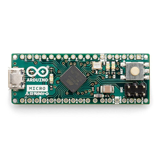
The Arduino Micro contains everything needed to support the microcontroller; simply connect it to a computer with a micro USB cable to get started. It has a form factor that enables it to be easily placed on a breadboard.
The Micro board is similar to the Arduino Leonardo in that the ATmega32U4 has built-in USB communication, eliminating the need for a secondary processor. This allows the Micro to appear to a connected computer as a mouse and keyboard, in addition to a virtual (CDC) serial / COM port.
Specifications
Microcontroller
ATmega32U4
Operating Voltage
5 V
Input Voltage
7 V - 12 V
Analog Input Pins
12
PWM Pins
7
DC I/O Pin
20
DC Current per I/O Pin
20 mA
DC Current for 3.3 V Pin
50 mA
Flash Memory
32 KB of which 4 KB used by the bootloader
SRAM
2.5 KB
EEPROM
1 KB
Clock Speed
16 MHz
LED_Builtin
13
Length
45 mm
Width
18 mm
Weight
13 g
Programming and Projects for the Minima and WiFi
Based on the low-cost 8-bit ATmega328P processor, the Arduino Uno R3 board is likely to score as the most popular Arduino family member, and this workhorse has been with us for many years. Eleven years later, the long-overdue successor, the Arduino Uno R4, was released. It is built around a 48 MHz, 32-bit Arm Cortex-M4 microcontroller and provides significantly expanded SRAM and Flash memory. Additionally, a higher-precision ADC and a new DAC are added to the design. The Uno R4 board also supports the CAN Bus with an interface.
Two versions of the board are available: Uno R4 Minima, and Uno R4 WiFi. This book is about using these new boards to develop many different and interesting projects with just a handful of parts and external modules. All projects described in the book have been fully tested on the Uno R4 Minima or the Uno R4 WiFi board, as appropriate.
The project topics include the reading, control, and driving of many components and modules in the kit as well as on the relevant Uno R4 board, including
LEDs
7-segment displays (using timer interrupts)
LCDs
Sensors
RFID Reader
4x4 Keypad
Real-time clock (RTC)
Joystick
8×8 LED matrix
Motors
DAC (Digital-to-analog converter)
LED matrix
WiFi connectivity
Serial UART
CAN bus
Infrared controller and receiver
Simulators
… all in creative and educational ways with the project operation and associated software explained in great detail.
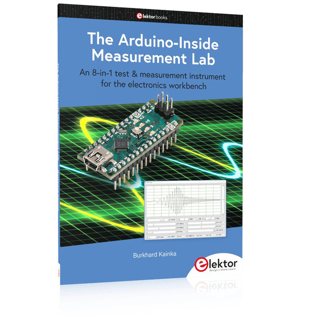
An 8-in-1 test & measurement instrument for the electronics workbench
A well-equipped electronics lab is crammed with power supplies, measuring devices, test equipment and signal generators. Wouldn‘t it be better to have one compact device for almost all tasks? Based on the Arduino, a PC interface is to be developed that’s as versatile as possible for measurement and control. It simply hangs on a USB cable and – depending on the software – forms the measuring head of a digital voltmeter or PC oscilloscope, a signal generator, an adjustable voltage source, a frequency counter, an ohmmeter, a capacitance meter, a characteristic curve recorder, and much more.
The circuits and methods collected here are not only relevant for exactly these tasks in the "MSR" electronics lab, but many details can also be used within completely different contexts.
Errata/Updates
In the programs printed, all instances of “be()” should read: sei().
Example projects with Node-RED, MQTT, WinCC SCADA, Blynk, and ThingSpeak
This comprehensive guide unlocks the power of Modbus TCP/IP communication with Arduino. From the basics of the Modbus protocol right up to full implementation in Arduino projects, the book walks you through the complete process with lucid explanations and practical examples.
Learn how to set up Modbus TCP/IP communication with Arduino for seamless data exchange between devices over a network. Explore different Modbus functions and master reading and writing registers to control your devices remotely. Create Modbus client and server applications to integrate into your Arduino projects, boosting their connectivity and automation level.
With detailed code snippets and illustrations, this guide is perfect for beginners and experienced Arduino enthusiasts alike. Whether you‘re a hobbyist looking to expand your skills or a professional seeking to implement Modbus TCP/IP communication in your projects, this book provides all the knowledge you need to harness the full potential of Modbus with Arduino.
Projects covered in the book:
TCP/IP communication between two Arduino Uno boards
Modbus TCP/IP communication within the Node-RED environment
Combining Arduino, Node-RED, and Blynk IoT cloud
Interfacing Modbus TCP/IP with WinCC SCADA to control sensors
Using MQTT protocol with Ethernet/ESP8266
Connecting to ThingSpeak IoT cloud using Ethernet/ESP8266
,
by Lobna Belarbi
Must-Have Boards, Kits & Tools to Start Your Arduino Journey with Elektor
Whether you're a newcomer eager to explore the world of microcontrollers or an experienced maker seeking to expand your toolkit, Elektor offers a curated selection...