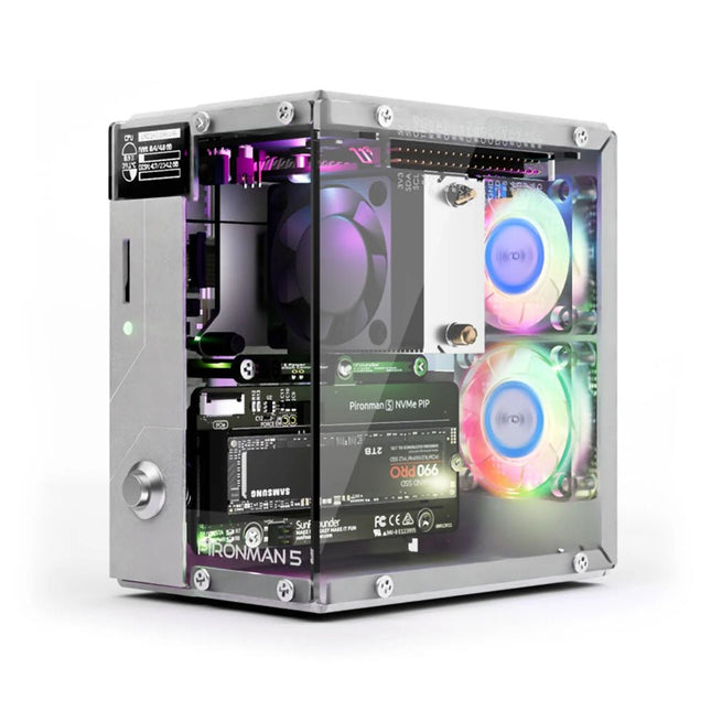
Enhance your Raspberry Pi 5 with the Pironman 5, built with sturdy aluminum, superior cooling, NVMe M.2 SSD support, OLED display, RGB lighting, standard HDMI ports x2, and a secure power switch. It is perfect for NAS, Home Assistant, Media and Game Centers. The Pironman 5 is not just a case; it’s an upgrade that transforms your Raspberry Pi 5 into a powerful, efficient, and stylish device.
The Pironman 5 includes the Pi 5 NVMe PIP (PCIe Peripheral Board), a PCIe adapter board specifically designed for NVMe solid-state drives. This board supports four sizes of NVMe SSDs: 2230, 2242, 2260, and 2280, all of which can be installed in an M.2 M key slot. The connection is certified for Gen 2.0 speeds (5 GT/sec), but can be forced to Gen 3.0 (10 GT/sec) for faster performance.
Expandable NVMe M.2 SSD Slot
Boost your Raspberry Pi 5's performance with the Pironman 5's NVMe M.2 SSD slot, supporting multiple sizes (2230, 2242, 2260, 2280) for increased storage and faster system response.
Advanced Cooling System
Keep your Raspberry Pi 5 cool and stylish with the Pironman 5's tower cooler and dual RGB fans, featuring dust filters for durable, low-maintenance operation.
OLED Display for Instant Insights
The Pironman 5 includes a 0.96" OLED display, providing immediate updates on CPU and RAM usage, temperature, IP address, and more.
Enhanced Functionality and Safety
The Pironman 5 secures your Raspberry Pi 5 with features like safe shutdown, customizable RGB LEDs, HDMI ports, an IR receiver, and an external GPIO extender, enhancing functionality and connectivity.
Features
Raspberry Pi 5 mini PC
0.96" OLED Display showing Raspberry Pi’s CPU usage, temperature, disk usage, IP address, RAM usage etc.
Tower cooler can cool a 100% CPU load Pi to 39°C at 25°C room temperature
2 RGB Fans, with GPIO control
1 PWM Fan on the Tower Cooler is controlled by the Raspberry Pi system.
Supports four (PCIe Gen 2.0 / PCIe Gen 3.0) NVMe M.2 SSD sizes: 2230, 2242, 2260, and 2280.
4 WS2812 Addressable RGB LED light up the whole case with cool light effect
IR Receiver for multi-media center like Kodi or Volumio
Retro metal power button for safe shut down
External GPIO extender with pin name label, for easy access
Equipped with a spring-loaded socket for easy card removal
Aluminum main body with clear Acrylic side panel
Features two standard HDMI ports
Downloads
Documentation
The ZD-915 is a digital desoldering station with ESD protection and digital display of both the actual and set value on an LCD screen. This desoldering station has high power in a compact and robust housing and makes desoldering easy, because it can be operated with one hand.
The ZD-915 features a soldering gun that houses a filter that catches any sucked material, so you only need to replace the filters to continue. There is also a temperature sensor in the tip so that temperature fluctuations can be quickly absorbed.
Features
The temperature is easily adjusted by simple up/down buttons.
140 W temperature controlled soldering station with adjustable range from 160°C to 480°C.
The desoldering station is designed for lead free desoldering specially.
The side of the station features a typical holder with sponge.
An illuminated power on/off is also loacted on the front.
Specifications
Station
Voltage supply
220-240 V
Power consumption
140 W
Vakuum pressure
600 mm HG
Desoldering Gun
Power consumption
24 V AC 80 WHeat up rating 130 W
Temperature
160-480 °C
Heating element
Ceramic heater
Included
1x ZD-915 Desoldering station
2x Spare soldering tip
3x Cleaning needle for desoldering tips
1x Spare filter for desoldering gun
1x Manual
The OWON SDS1102 is an affordable benchtop digital oscilloscope that combines solid performance with essential measurement features. This 2-channel oscilloscope offers a 100 MHz bandwidth, a 1 GS/s sampling rate, a 7-inch LCD display, and a 10 kpts memory depth, making it a practical choice for everyday electronics testing, troubleshooting, and education.
The SDS1102 features a simplified trigger system with level and edge triggering, making it easy to capture and analyze common signals. It is designed for applications that do not require deep memory or advanced trigger functions, offering a straightforward and cost-effective solution for basic signal analysis.
Features
Bandwidth: 100 MHz
2 channels
Sample rate: 1 GS/s
Ultra-thin body
7-inch high-res LCD
SCPI and LabVIEW supported
Specifications
Bandwidth
100 MHz
Horizontal Scale (s/div)
5 ns/div – 1000 s/div
Channel
2
Vertical Sensitivity
5 mV/div – 5 V/div (at input)
DC Gain Accuracy
3%
Vertical Resolution (A/D)
8 bits (2 channels simultaneously)
Input
Input Impedance
1 MΩ, 10 pF
Input Coupling
AC, DC, GND
Max Input Voltage
±400 V, CATI, CATII
Passive probes
х1; х10
Probe Attenuation Factor
х1; х10; х100; х1000
Trigger System
Trigger Mode
Auto, Normal, Single
Trigger Type
Edge, Video
Edge Trigger Source
CH1, CH2
Video Trigger
Sampling Type
Real-time
Sample Rate
1 GS/s
Equivalent Sample Rate
No
Wavelength
10K pts
Interpolation
sin(x)/x
Measurement and Mathematical Treatment System
Automatic Measurement
Vpp, Vavg, RMS, Frequency, Period, Vmax, Vmin, Vtop, Vbase, Width, Overshoot, Pre-shootRise time, Fall time, +Width, -Width, +Duty, -Duty, Delay A→B, Delay A→B, area, cycle area
Math Functions
Addition, Subtraction, Multiplication, Division, FFT
General Characteristics
Display type
7" color LCD
Display Resolution
800 x 480
Power
100-240 V, 45-440 Hz, <15 W
Dimensions
301 x 70 x 152 mm
Weight
1.1 kg
Included
1x OWON SDS1102 Oscilloscope
2x Oscilloscope probes
1x Probe adjust
1x Mains power cord
1x USB cable
1x CD-Rom
1x Quick guide
Downloads
Quick Guide
Manual
PC Software
SCPI Commands
This upgraded version 2.0 (available exclusively from Elektor) contains the following improvements:
Enhanced protective earthing (PE) for furnace chassis
Extra thermal insulation layer around furnace to reduce odors
Connection to a computer, allowing curve editing on a PC
Features such as constant temperature control and timing functions
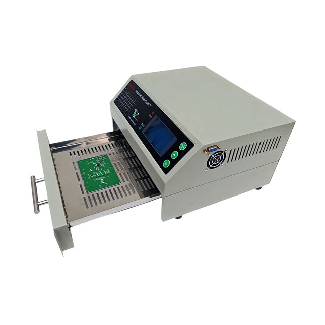
The infrared IC heater T-962 v2.0 is a microprocessor-controlled reflow oven that you can use for effectively soldering various SMD and BGA components. The whole soldering process can be completed automatically and it is very easy to use. This machine uses a powerful infrared emission and circulation of the hot air flow, so the temperature is being kept very accurate and evenly distributed.
A windowed drawer is designed to hold the work-piece, and allows safe soldering techniques and the manipulation of SMDBGA and other small electronic parts mounted on a PCB assembly. The T-962 v2.0 may be used to automatically rework solder to correct bad solder joints, remove/replace bad components and complete small engineering models or prototypes.
Features
Large infrared soldering area
Effective soldering area: 180 x 235 mm; this increases the usage range of this machine drastically and makes it an economical investment.
Choice of different soldering cycles
Parameters of eight soldering cycles are pre defined and the entire soldering process can completed automatically from Preheat, Soak and Reflow through to cool down.
Special heat up and temperature equalization with all designs
Uses up to 800 Watts of energy efficient Infrared heating and air circulation to re-flow solder.
Ergonomic design, practical and easily operated
Good build quality but at the same time light weight and a small footprint allows the T-962 v2.0 to be easily bench positioned transported or stored.
Large number of available functions
The T-962 v2.0 can solder most small parts of PCB boards, for example CHIP, SOP, PLCC, QFP, BGA etc. It is the ideal rework solution from single runs to on-demand small batch production.
Specifications
Soldering area (max)
180 x 235 mm (7.1 x 9.3")
Power (max)
800 W
Temperature range
0-280°C (32-536°F)
Heating method
Infrared
Processing time
1~8 minutes
Power supply
220 V AC/50 Hz
Display
LCD with Backlight
Control mode
8 intelligent temperature curves
Dimensions
310 x 290 x 170 mm (12.2 x 11.4 x 6.7")
Weight
6.2 kg
Included
1x T-962 v2.0 Reflow Soldering Oven (Elektor Version)
2x Fuses
1x Power cord (EU)
Downloads
Manual
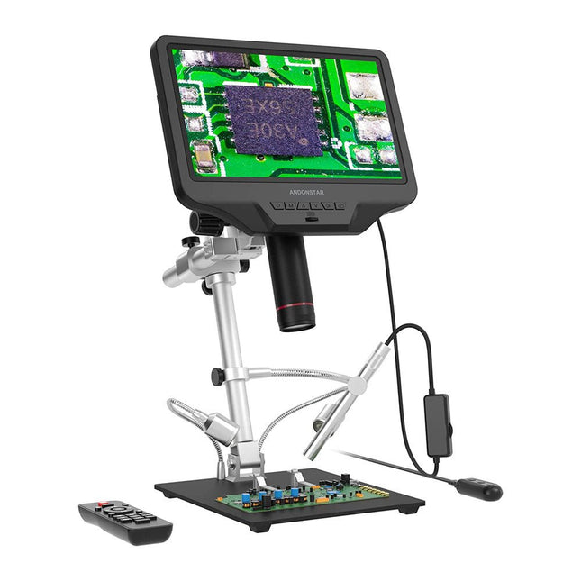
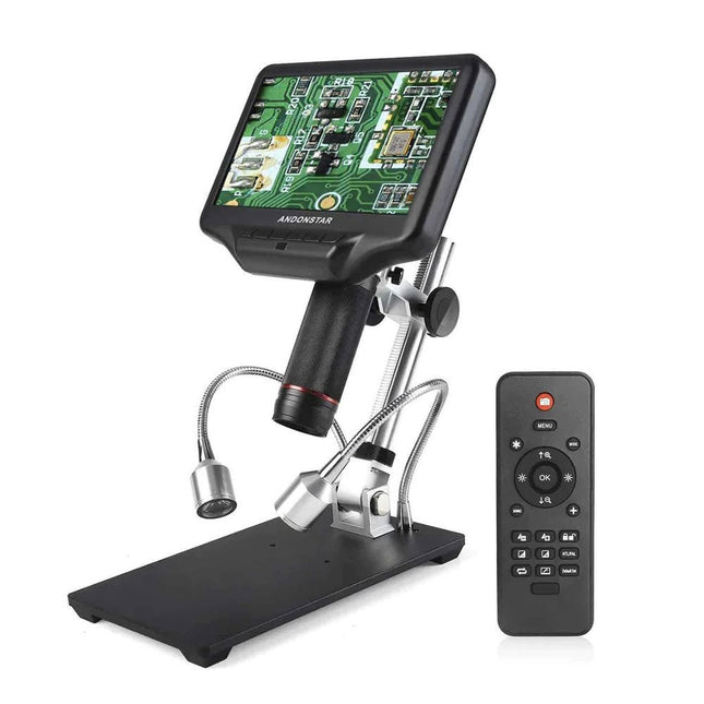
The Andonstar AD409 Pro-ES is a digital microscope with an extra-high stand that is also equipped with an endoscope. The microscope allows clear observation of the sides of components, the inside of pipes, etc., enabling 360° observation without dead angles. The microscope also has a remote control that allows you to easily switch between the following image modes: two-lens, microscope and endoscope.
Features
High-quality metal lens and focusing barrel
Professional HDMI digital microscope supports multiple output methods
Soldering Microscope with Pro Metal Stand
Unique UV filter design
8 Levels adjustable LED Lights
Convenient Wireless Remote Control
Professional Measurement Software
Specifications
Screen size
10.1 inch (25.7 cm)
Image sensor
4 MP
Video output
UHD 2880x2160 (24fps)FHD 1920x1080 (60fps/30fps)HD 1280x720 (120fps)
Video format
MP4
Magnification
Up to 300 times (27 inch HDMI monitor)
Photo resolution
Max. 12 MP (4032x3024)
Photo format
JPG
Focus range
Min. 5 cm
Frame Rate
Max. 120fps
Video interface
HDMI
Storage
microSD card (up to 64 GB)
PC support
Windows, PC software with measurement
Mobile phone, tablet terminal support
Support WiFi connection and measurement
Power source
5 V DC
Light source
2 LEDs with the stand
Endoscope
Yes
Stand size
18 x 20 x 32 cm
Included
1x Andonstar AD409 Pro-ES Digital Microscope
1x Endoscope
1x Metal stand with 2 LEDs
1x UV filter (already assembled in the lens)
1x IR remote
1x Switch cable
1x Power adapter
1x Wrench
2x Metal clips
1x HDMI cable
1x User manual
Downloads
Manual
Software
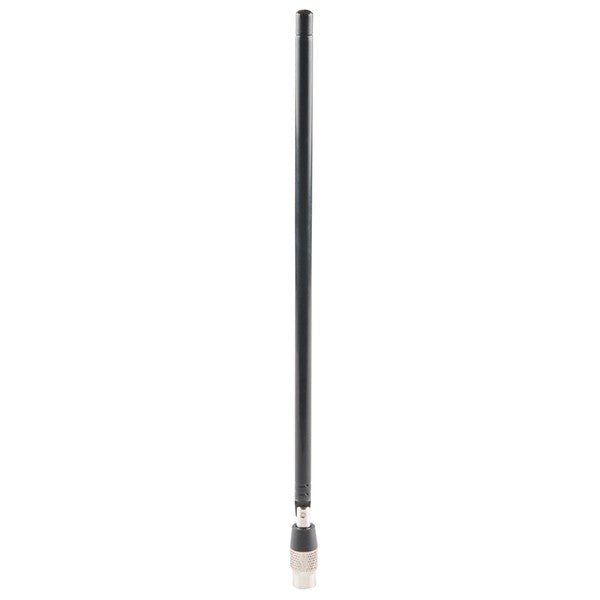
ANT500 from Great Scott Gadgets is a telescopic antenna designed for operation from 75 MHz to 1 GHz. Its total length is configurable from 20 cm to 88 cm. ANT500 is constructed of stainless steel and features an SMA male connector, rotating shaft, and adjustable elbow.
ANT500 is a 50 ohm general purpose antenna. It is the perfect first antenna for use with HackRF One/Pro.
Examine your circuits with high precision and solder even the smallest SMDs and elements without any hassle.
Features
Multifunctional HDMI Digital Microscope features Full HD, comfortable headroom, improved ergonomy, multiple output signals with different resolutions.
Tilt angle of the wide LCD monitor is adjustable.
Comes with remote control.
Can be used as stand-alone.
Specifications
Screen size
7 inch (17.8 cm)
Image sensor
4 MP
Video output
UHD 2880x2160 (24fps)FHD 1920x1080 (60fps/30fps)HD 1280x720 (120fps)
Video format
MP4
Magnification
Up to 270 times (27 inch HDMI monitor)
Photo resolution
Max. 12 MP (4032x3024)
Photo format
JPG
Focus range
Min. 5 cm
Frame rate
Max. 120fps (under 600 Lux Brightness & HDP120)
Video interface
HDMI
Storage
microSD card (up to 32 GB)
Power source
5 V DC
Light source
2 LEDs with the stand
Stand size
20 x 12 x 19 cm
Included
1x Andonstar AD407 Digital Microscope
1x Metal stand with 2 LEDs
1x Optical bracket
1x UV filter
1x IR remote
1x Switch cable
1x Power adapter
1x HDMI cable
2x Screws
1x Screwdriver
1x User manual
Downloads
Manual
Model Comparison
AD407
AD407 Pro
AD409
AD409 Pro-ES
Screen size
7 inch (17.8 cm)
7 inch (17.8 cm)
10.1 inch (25.7 cm)
10.1 inch (25.7 cm)
Image sensor
4 MP
4 MP
4 MP
4 MP
Video output
2160p
2160p
2160p
2160p
Interfaces
HDMI
HDMI
USB, HDMI, WiFi
USB, HDMI, WiFi
Video format
MP4
MP4
MP4
MP4
Magnification
Up to 270x
Up to 270x
Up to 300x
Up to 300x
Photo resolution
Max. 4032x3024
Max. 4032x3024
Max. 4032x3024
Max. 4032x3024
Photo format
JPG
JPG
JPG
JPG
Focus distance
Min. 5 cm
Min. 5 cm
Min. 5 cm
Min. 5 cm
Frame rate
Max. 120f/s
Max. 120f/s
Max. 120f/s
Max. 120f/s
Storage
microSD card
microSD card
microSD card
microSD card
PC support
No
No
Windows
Windows
Mobile connection
No
No
WiFi + Measurement
WiFi + Measurement
Power source
5 V DC
5 V DC
5 V DC
5 V DC
Light source
2 LEDs with the stand
2 LEDs with the stand
2 LEDs with the stand
2 LEDs with the stand
Endoscope
No
No
No
Yes
Stand size
20 x 12 x 19 cm
20 x 18 x 32 cm
18 x 20 x 30 cm
18 x 20 x 32 cm
Weight
1.6 kg
2.1 kg
2.2 kg
2.5 kg
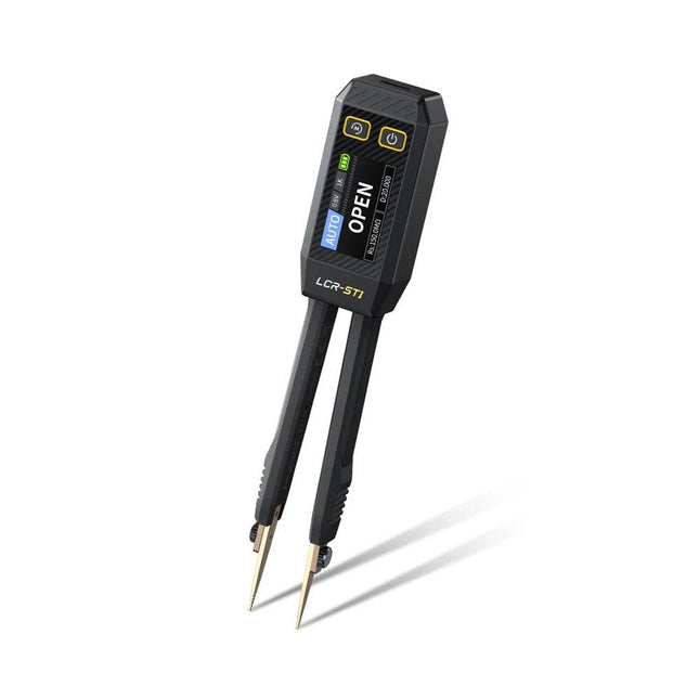
The FNIRSI LCR-ST1 is a compact, multifunctional, and smart LCR tester that supports automatic measurements of resistance, capacitance, inductance, diode testing, and continuity.
Its 1.14-inch color display combined with a convenient magnetic adsorption function enhances ease of use, while the built-in 250 mAh lithium battery ensures long-lasting performance. The device supports three frequency ranges (100 Hz, 1 kHz and 10 kHz) and offers 0.3 V and 0.6 V RMS test levels for versatile testing applications.
The unique tweezer-shaped design of the LCR-ST1 is ideal for delicate tasks in confined spaces and enables fast and accurate testing of electronic components. Its light weight and portable design make it an invaluable tool for both field and laboratory use.
Whether you are an experienced engineer or just starting out in electronics, the LCR-ST1 delivers reliable and accurate measurement results, allowing you to complete your tasks with greater efficiency and precision.
Features
Offers 3 test frequencies (100 Hz, 1 kHz, 10 kHz) and 2 test voltage levels.
Features automatic component identification for faster and more reliable measurements.
High-resolution 1.14-inch color display for clear readouts.
Supports automatic data recording and storage.
The tweezer tips are made from gold-plated brass for enhanced durability and conductivity.
Specifications
Resistance Range
10 mΩ – 10 MΩ
Capacitance Range
1 pF – 22 mF
Inductance Range
1 μh – 10 H
Diode
On voltage 0.7 V
Frequency Test
100 Hz, 1k Hz, 10 KHz
Level Test
0.3 V, 0.6 V RMS
Parameter Display
ESR, D value, Q value, Z value, X value
Display
1.14" HD color screen
Charging Interface
USB-C, 5 V/1 A
Power Supply
Built-in 250 mAh lithium battery
Auto Recognition Measurement
Yes
Replaceable Tweezer Head
Yes
Auto Shutdown
Yes
Data Hold
Yes
History Record
Connect to PC to view and export
Dimensions
28 x 19 x 150 mm
Weight
41 g
Included
1x LCR-ST1 SMD Tweezers
2x Hook Tips
1x Magnetic Patch
1x USB cable
1x Tool bag
1x Manual
Downloads
Manual
Firmware V1.6
The FNIRSI HRM-10 is a portable, high-precision battery internal resistance and voltage tester. This device offers true four-wire measurement and is designed for both accuracy and ease of use. It automatically measures internal resistance and voltage values simultaneously, displaying the results on its HD color screen. Users have the option to manually adjust voltage and resistance ranges to suit their needs. The device also includes a sorting mode that automatically filters the good and bad batteries based on user-set thresholds. Additionally, it supports the storage of historical data and allows for exporting measurement records in table format.
Features
High Measurement Accuracy
Tabular Data Export
Auto-Evaluate Measurement Results
8 Threshold Settings
HD Color Screen
Folding Stand
1000 mAh Lithium Battery
Specifications
Voltage
Resistance
Measuring range
0-100 V (DC)
0-200 Ω
Accuracy
±0.5%
±0.5%
Gear
Automatic, 1 V, 10 V, 100 V
Automatic, 20 mΩ, 200 mΩ, 2 Ω, 20 Ω, 200 Ω
Instrument test signal frequency
1 Khz (AC)
Rechargeable
USB-C (5 V/1 A)
Built-in battery
1000 mAh lithium battery
User calibration
Yes
Sorting mode
Yes
History record
Yes
Recorded data export
Yes
Working environment
–10°C to +45°C, relative humidity <80%
Storage environment
–20°C to +80°C, relative humidity <80%
Dimensions
158.7 x 80.5 x 28.4 mm
Weight
225 g
Included
1x FNIRSI HRM-10 Internal Resistance Tester
1x Clip Test Line
1x USB-C data cable
1x Manual
Downloads
Manual
Firmware V0.3
The FNIRSI FNB58 USB tester (with Bluetooth) is a comprehensive and very accurate USB voltage and current meter. It features a 2.0-inch full-color HD TFT display, built-in USB-A, micro USB and USB-C interface. With this device you can measure the power supply or power consumption of products or the charging power of cell phones and power supplies. You can also determine the fast charging protocol of chargers.
Features
USB-A and USB-C interface
2.0" HD display
Data at a glance
Wide compatibility
Ultra-precise data detection
Play with fast charging technology
Automatic protocol detection (PD2.0, 3.0, 3.1, PPS, QC2.0, 3.0, FCP, SCP, AFC, PE, DASH VOOC, SuperVOOC and more)
Simple user interface, easy to operate
4 function curve displays (real-time voltage and current curve, offline curve recording, D+/D- voltage curve, high-speed power supply ripple measurement)
Cable detection
10 groups of energy recording battery capacity calculation
PC connectivity for data logging and firmware updates
Bluetooth app for Android devices
Specifications
Voltage range
4-28 V
Current range
0-7 A
Power range
0-120 W
Load equivalent internal resistance
0-9999.9 Ω
D+/D- voltage
0-3.3 V
Capacity
0-9999.99 Ah
Power consumption
0-9999.99 Wh
Cable resistance
0-9999.9 Ω
Interfaces
micro USB, USB-A, USB-C
Dimensions
42 x 13 x 82 mm
Downloads
Manual
Firmware V0.68
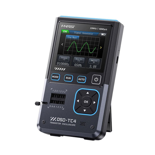
The FNIRDSI DSO-TC4 is a multifunctional transistor oscilloscope that is both comprehensive and practical. It is designed for use in maintenance and R&D applications, integrating an oscilloscope, transistor tester, and signal generator into a single device.
Features
Equipped with a 2.8-inch TFT color screen for a clear and intuitive display
Built-in high-capacity rechargeable lithium battery (1500 mAh) with a standby time of up to 4 hours
Compact and lightweight, ideal for mobile use
Specifications
Oscilloscope
Analog Bandwidth
10 MHz
Real-Time Sampling Rate
48 MSa/s
Input Impedance
1 MΩ
Coupling Mode
AC/DC
Test Voltage Range
1:1 Probe: 80 Vpp (+40 V)
10:1 Probe: 800 Vpp (+400 V)
Vertical Sensitivity
10 mV/div~10 V/div (X1 range)
Vertical Displacement
Adjustable with indication
Time Base Range
50ns~20s
Trigger Mode
Auto/Normal/Single
Trigger Type
Rising edge, Falling edge
Trigger Level
Adjustable with indication
Waveform Freeze
Yes (HOLD function)
Automatic Measurement
Max, Min, Avg, RMS, Vpp, Frequency, Cycle, Duty Cycle
Component Tester
Transistor
Amplification factor "hfe"; Base-Emitter voltage "Ube", Ic/Ie, Collector-Emitter reverse leakage current "Iceo", Ices, Forward voltage drop of protection diode "Uf"
Diode
Forward voltage drop <5 V (Forward voltage drop, Junction capacitance, Reverse leakage current)
Zener Diode
0.01~32 V
Reverse Breakdown Voltage (K-A-A Test Area)
Field-Effect Transistor (FET)
JFET: Gate capacitance "Cg", Drain current Id under "Vgs", Forward voltage drop of protection diode "Uf"
IGBT: Drain current Id under Vgs, Forward voltage drop of protection diode Uf
MIOSTET: Threshold voltage "Vt", Gate capacitance "Cg", Drain-Source resistance "Rds", Forward voltage drop of protection diode "Uf"
Unidirectional SCR
Trigger voltage <5V, Gate level (Gate voltage)
Bidirectional SCR
Trigger current <6mA (Gate voltage)
Capacitor
25pF~100mF, Capacitance value, Loss factor "Vloss"
Resistor
0.01Ω~50MΩ
Inductor
10μH~1000μH, DC resistance
DS18B20
Temperature sensor, Pins: GND, DQ, VDD
DHT11
Temperature and humidity sensor, Pins: VDD, DATA, GND
Signal Generator
Output Waveform
Supports 13 waveform outputs
Waveform Frequency
0-50 KHz
Square Wave Duty Cycle
0-100%
Waveform Amplitude
0.1-3.0 V
General
Display
2.8-inch TFT color screen
Backlight
Brightness adjustable
Power Supply
USB-C (5 V/1 A)
Battery
3.7 V/1500 mAh
Languages
English, German, Spanish, Portuguese, Russian, Chinese, Japanese, Korean
Dimensions
90 x 142 x 27.5 mm
Weight
186 g
Included
1x FNIRSI DSO-TC4 (3-in-1) Oscilloscope (10 MHz)
1x P6100 Oscilloscope probes (10X)
1x Alligator clip probe
3x Test hooks
1x Adapter
1x USB-C charging cable
1x Manual
Downloads
Manual
Firmware V0.0.7 (+V1.0.9)
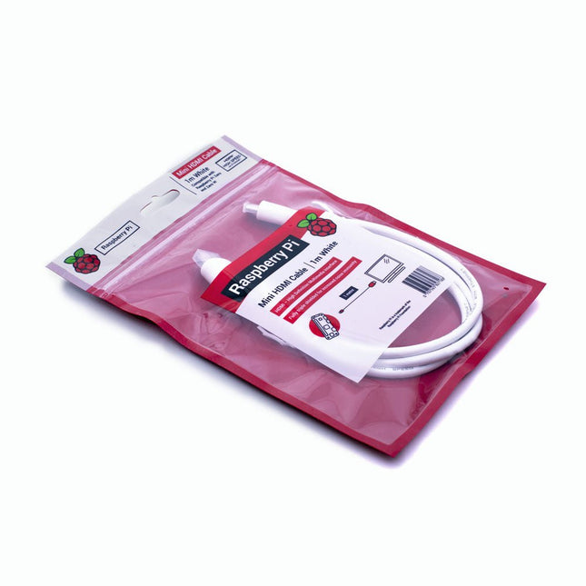
The official Raspberry Pi mini-HDMI to HDMI (A/M) cable designed for all Raspberry Pi Zero models. 19-pin HDMI Type D(M) to 19-pin HDMI Type A(M) 1 m cable (white) Nickel-plated plugs 4Kp60 compliant RoHS compliant 3 Mohm 300 VDC insulation, withstands 300 VDC for 0.1s
Fumes released during the soldering process are potentially harmful to health. This solder fume extractor is securely fastened to the work table with a bracket. Thanks to the 3 axes, the solder fume extractor can be positioned perfectly, i.e. directly above the rising solder fumes. The harmful solder fumes are extracted by a powerful but quiet fan and filtered by an activated-carbon filter mat.
Features
Removes solder fumes
Absorbs toxic gases and fumes from brazing operations
Helps reduce the likelihood of headaches, eye irration and neusea
Adjustable absorption angle for accurate placement
Easy replaceable activated carbon filter
High-performance fan
Low noise and long life service
Specifications
Absorption capacity: 1 m³/min (max.)
Power consumption: 23 W
Power supply: 220-240 VAC
Amount of activated carbon filter: 7 g
Maximum absorption weight: 2 g
Dimensions: 220 x 270 x 168 mm (W x H x D)
Weight: 1.4 kg
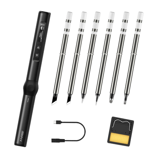
The perfect tool for quick repairs
The FNIRSI HS-01 is a powerful, adjustable smart soldering iron with a built-in 0.87-inch OLED display that quickly reaches temperatures between 80-420°C (180-780°F). The display shows all important information, including the status of the temperature level, the set temperature, the supply voltage and the power percentage. You can set the input voltage from 9-20 V directly in the menu according to your needs. The integrated sleep mode automatically turns off the iron after 30 minutes.
Features
96 W input (DC)
65 W PD power
OLED display
Constant temperature & fast heating
CNC metal integral molding
Smart safety anti-scald
Mini pocket size
Ergonomic design
Aluminum material
Left/right hand switch
Efficient heat radiation
Inductive sleep
Color: Black
Specifications
Power
65 W
Screen
0.87" OLED
Operating voltage
9-20 VDC
Power supply
USB-C
Temperature range
80-420°C (180-780°F)
Fast charging protocol
PD trigger
Dimensions
184 x 20 x 20 mm (7.24 x 0.79 x 0.79')
Weight
56 g
Power Selection
Operating voltage
20 V
15 V
12 V
9 V
Operating current
≥3.25 A
≥2.5 A
≥2 A
≥1.5 A
Power
65 W
37.5 W
24 W
13.5 W
Tin melting time
8s
12s
17s
30s
Included
1x FNRISI HS-01 smart soldering iron
6x Soldering iron tips (HS01-BC2, HS01-KR, HS01-K65, HS01-B2, HS01-ILS, HS01-BC3)
1x DC to USB-C power cable
1x Mini soldering iron stand
1x Manual
Required
Power adapter
USB-C cable
Downloads
Manual
Firmware V0.3.s19
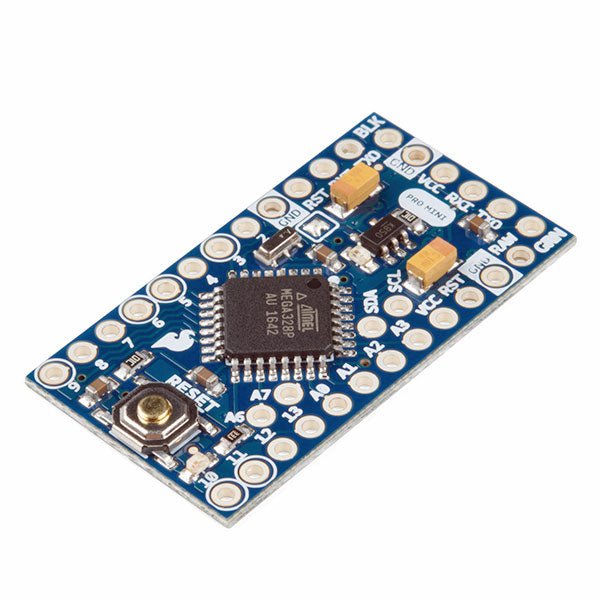
The Arduino Pro Mini is a microcontroller board based on the ATmega328P.
It has 14 digital input/output pins (of which 6 can be used as PWM outputs), 6 analog inputs, an on-board resonator, a reset button, and holes for mounting pin headers. A six pin header can be connected to an FTDI cable or SparkFun breakout board to provide USB power and communication to the board.
The Arduino Pro Mini is intended for semi-permanent installation in objects or exhibitions. The board comes without pre-mounted headers, allowing the use of various types of connectors or direct soldering of wires. The pin layout is compatible with the Arduino Mini.
The Arduino Pro Mini was designed and is manufactured by SparkFun Electronics.
Specifications
Microcontroller
ATmega328P
Board Power Supply
5-12 V
Circuit Operating Voltage
5 V
Digital I/O Pins
14
PWM Pins
6
UART
1
SPI
1
I²C
1
Analog Input Pins
6
External Interrupts
2
DC Current per I/O Pin
40 mA
Flash Memory
32 KB of which 2 KB used by bootloader
SRAM
2 KB
EEPROM
1 KB
Clock Speed
16 MHz
Dimensions
18 x 33.3 mm (0.7 x 1.3")
Downloads
Eagle files
Schematics
The OWON XDM1041 is a fast, high-precision digital True RMS benchtop multimeter with a high-resolution 3.5-inch LCD and 50,000 counts. Its DC voltage accuracy is up to 0.05% and it can measure up to 65 values per second.
Features
3.5“ high-resolution LCD (480x320 pixels)
55000 counts, DC voltage accuracy up to 0.05%
Up to 65 readings per second
Dual line display supported
Trend analysis accessible in chart mode
AC True RMS measurements (bandwidth: 20 Hz – 1 kHz)
SCPI support: Remote control the multimeter through PC software via USB port
Data record function, you can record the measured data into internal memory, and then read and process the recorded data with your computer.
Specifications
Measurement Range
Resolution
Accuracy
DC Voltage
50.000 mV
0.001 mV
0.1% +10
500.00 mV
0.01 mV
0.05% +5
5.0000 V
0.0001 V
0.05% +5
50.000 V
0.001 V
0.05% +5
500.00 V
0.01 V
0.1% +5
1000.0 V
0.1 V
0.1% +10
AC Voltage
500 mV~750 V
20 Hz~45 Hz
1% +30
45 Hz~65 Hz
0.5% +30
65 Hz~1 KHz
0.7% +30
DC Current
500 uA
0.01 uA
0.15% +20
5000 uA
0.1 uA
0.15% +10
50 mA
0.001 mA
0.15% +20
500 mA
0.01 mA
0.15% +10
5 A
0.0001 A
0.5% +10
10 A
0.001 A
0.5% +10
AC Current
500 uA~500 mA
20 Hz~1 KHz
0.5% +20
5 A-10 A
1.5% +20
Resistance
500 Ω
0.01 Ω
0.15% +10
5 KΩ
0.0001 KΩ
0.15% +5
50 KΩ
0.001 KΩ
0.15% +5
500 KΩ
0.01 KΩ
0.15% +5
5 MΩ
0.0001 MΩ
0.3% +5
50 MΩ
0.001 MΩ
1% +10
Frequency
10.000 Hz~60 MHz
/
±(0.2% +10)
Capacitance
50 nF~500 uF
/
2.5% +10
5 mF~50 mF
5% +10
Diode
3.0000 V
0.0001 V
/
Continuity
1000 Ω
0.1 Ω
Adjustable threshold
Temperature
K type, PT100
Max Display
55,000 counts
Data-logging Function
Logging Duration
15ms~9999.999s
Logging Length
1,000 points
Display
3.5“ TFT LCD (480x320 pixels)
Power supply
230 V AC mains voltage
Dimensions
200 x 88 x 150 mm
Weight
approx. 0.5 kg
Included
1x OWON XDM1041 Multimeter
1x Power cord
2x Test leads
1x Fuse
1x USB cable
1x Manual
Downloads
Programming Manual
PC Software
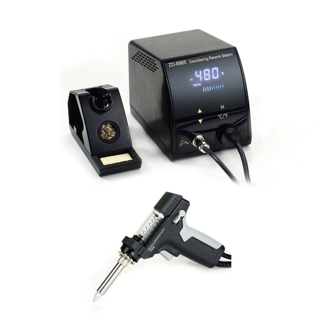
The ZD-8965 is a digital temperature-controlled desoldering station equipped with ground protection and an LCD screen for temperature display. Despite its compact and robust design, this high-power desoldering station is easy to operate with just one hand.
The ZD-8965 features a soldering gun with an integrated filter that captures any extracted material, allowing for continuous operation by simply replacing the filters. Additionally, a temperature sensor is embedded in the tip, enabling rapid response to temperature fluctuations for consistent performance.
Features
Effortlessly adjust the temperature between 160°C and 480°C using the convenient up/down buttons on the front panel.
LED display to indicate the temperature in °C/°F
Features an ergonomic pistol grip with a trigger for quick and efficient solder waste removal.
The upgraded soldering gun includes a rear trigger, making it exceptionally convenient for replacing and cleaning components.
Comes with a high-quality soldering gun and a sturdy holder.
Equipped with a heavy-duty heater that ensures optimal desoldering performance every time.
Specifications
Station
Voltage supply
220-240 V
Power
140 W
Vakuum pressure
600 mm HG
Desoldering Gun
Power
140 W (18 V DC)Heat up rating: 140 W
Temperature
160-480°C (320-896°F)
Heating element
Ceramic heater
Included
1x ZD-8965 Desoldering station
2x Spare soldering tips
3x Cleaning needles for desoldering tips
3x Spare filter for desoldering gun
1x Spare filter for desoldering station
1x Manual
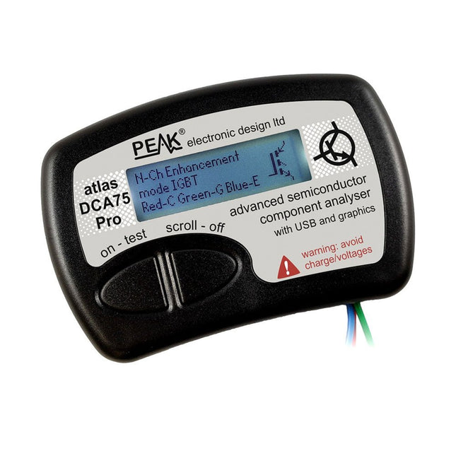
The DCA75 Pro is a great instrument that combines ease-of-use with amazing features. It can automatically identify a huge range of semiconductors, automatically identify pinouts and measure detailed parameters.
Features
Built-in graphics display (now backlit) to show detailed schematic of the component you're testing as well as pinout and measurement data
USB connectivity to allow curve tracing, data storage/retrieval and device matching on your Windows PC (Windows 7 and higher)
Single internal AAA alkaline cell for standalone operation
Component Support
Bipolar transistors (NPN/PNP inc Silicon/Germanium)
Darlington transistors (NPN/PNP)
Enhancement mode MOSFETs (N-Ch and P-Ch)
Depletion mode MOSFETs (N-Ch and P-Ch)
Junction FETs (N-Ch and P-Ch). Both symmetrical and asymmetrical types
Enhancement IGBTs (N-Ch and P-Ch)
Diodes and diode networks (2 and 3 lead types)
Zener diodes (up to about 9 V)
Voltage regulators (up to about 8 V)
LEDs and bi-colour LEDs (2 lead and 3 lead types)
Low power sensitive Triacs and Thyristors (<10 mA trigger and hold)
Measurements
BJT current gain (hFE)
BJT base emitter voltage (Vbe)
BJT collector leakage current
MOSFET on and off gate threshold voltages
MOSFET transconductance
JFET pinch-off voltage
JFET transconductance
JFET IDSS (drain current for Vgs=0)
IGBT on and off gate threshold voltages
IGBT transconductance
Voltage regulator output voltage
Voltage regulator quiescent current consumption
Voltage regulator drop-out voltage
Zener voltage
Diode forward voltage drop
Specifications
Analyzer type
Semiconductor components
Component detection
Automatic
Pinout detection
Automatic, connect any way round
Display type
Graphic LCD (now backlit)
Interface type
USB for optional PC connection
PC functions
Curve tracing (Windows 7 and higher)
Software
Included on USB drive for Windows 7 and higher
Battery
Single AAA cell (supplied)
Included
Peak Atlas DCA75 Pro
PC software on a USB Flash Drive for Windows 11, 10, 8, 7, XP
Micro USB cable
Fitted universal premium hook probes
AAA Alkaline battery
Downloads
Datasheet (EN)
User Guide (EN)
User Guide (IT)
Software Installation Guide (EN)
Software and Firmware Package
The FNIRSI SG-003A multi-functional Signal Generator a.k.a. Process Meter/Calibrator is a high-precision voltage/current generator and meter. The SG-003A provides highly accurate reference voltages or currents for testing and calibrating other measurement instruments like multimeters and oscilloscopes.
Besides voltages and currents, the SG-003A also generates rectangular pulse signals with precisely programmable frequencies and duty cycles. Its converter mode turns the SG-003A into a precision voltage-controlled current source, or current-controlled voltage source, and even a voltage- or current-controlled frequency generator.
The SG-003A is a great tool for checking your multimeter’s accuracy and precision, and for testing e.g. LEDs.
Features
Accuracy (voltage/current)
0.1% ±0.005
Resolution (current)
0.01 mA
Frequency
0-10 kHz
Resolution
5 digits
Output power
24 V
Display
2.4" TFT LCD (320 x 240)
Dimensions
92 x 72 x 30 mm
Weight
165 g
Specifications
Signal
Range
Precision
Resolution
Max load
External power supply
Active current output
0~24 mA
±(0.1% + 0.005)
0.01 mA
750 Ω
Passive current output (XMT)
0~24 mA
±(0.1% + 0.005)
0.01 mA
0~30 V
Voltage output
0~24 V
±(0.1% + 0.005)
0.01 V
24 V loop
0~24 mA
±(0.1% + 0.005)
0.01 mA
Frequency output
0~9999 Hz
±2%
5 digits
Current input
0~24 mA
±(0.1% + 0.005)
0.01 mA
Voltage input
0~30 V
±(0.1% + 0.005)
0.01 V
Included
1x FNIRSI SG-003A Signal generator
4x Test clips
1x USB charger
1x USB-C cable
1x Manual
Downloads
Manual
Firmware V4.3
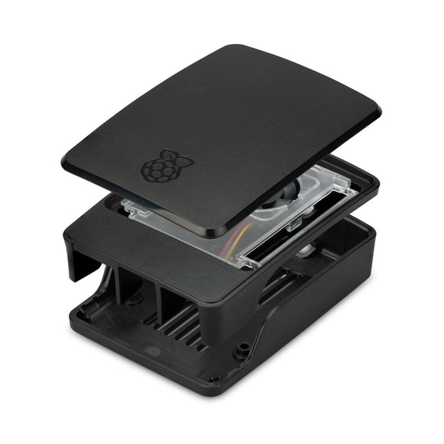
The Raspberry Pi 5 case is a refinement of the Raspberry Pi 4 case with improved thermal features to support the higher peak power consumption of the Raspberry Pi 5. It integrates a variable speed fan that is powered and controlled via a dedicated connector on the Raspberry Pi 5.
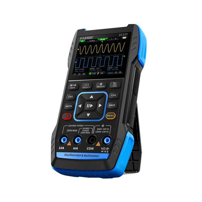
The FNIRSI 2C53T, an enhanced version of its 10 MHz predecessor, is a compact and versatile 3-in-1 device. It combines a dual-channel 50 MHz oscilloscope, a 4.5-digit True RMS multimeter, and a signal generator with 13 waveform types, making it an essential tool for maintenance and research professionals.
Oscilloscope: Features 50 MHz bandwidth, 250 MS/s sampling rate, ±400 V protection, FPGA + ARM + ADC architecture, and waveform saving for analysis.
Multimeter: 4.5-digit True RMS with 19999 counts, supports AC/DC voltage, current, capacitance, resistance, diode, and continuity measurements.
Signal Generator: Outputs 13 signal types up to 50 KHz, with adjustable frequency, amplitude, and duty cycle.
With a 2.8-inch LCD, 3000 mAh battery (6-hour runtime), and a portable design, it delivers powerful functionality in a user-friendly package.
Specifications
Oscilloscope
Channels
2
Analog Bandwidth
50 MHz
Real-time Sampling Rate
250 MS/s
Storage Depth
1 Kpts
Impedance
1 MΩ
Time Base Range
10ns-20s
Vertical Sensitivity
10 mV/div-10 V/div (x1)
Maximum Measured Voltage
±400 V
Trigger Mode
Auto/Normal/Single
Trigger Type
Rising edge, Falling edge
Display Mode
Y-T/Rolling/X-Y
Coupling Method
AC/DC
Persistence
OFF, 500ms, 1s, ∞
Math
8 Basic Operations + FFT
Supported
Waveform Screenshot Save, Export Waveform Image, Cursor Measurement, Infinite Afterglow
Multimeter
DC Voltage
1.9999V/19.999V/199.99V/1000V
±(0.5%+3)
AC Voltage
1.9999V/19.999V/199.99V/750.0V
±(1%+3)
DC Current
19.999mA/199.99mA/1.9999A/9.999A
±(1.2%+3)
AC Current
19.999mA/199.99mA/1.9999A/9.999A
±(1.5%+3)
Resistance
19.999MΩ/1.9999MΩ/199.99KΩ/19.999KΩ
±(0.5%+3)
1.9999KΩ/199.99Ω
±(2.0%+3)
Capacitance
999.9uF/99.99uF/9.999uF/999.9nF/99.99nF/9.999nF
±(2.0%+5)
9.999mF/99.99mF
±(5.0%+20)
Temperature
−55~1300°C (−67~2372°F)
±(2.5%+5)
Continuity Test
Yes
Diode
Yes
Signal Generator
13 Signal Waveforms
Sine wave, rectangular wave, sawtooth wave, half wave, full wave, positive step wave, reverse step wave, exponential rise, exponential fall, DC, multi-audio, Sinker pulse, Lorentz wave
Output Frequency
0-50 KHz
Output Amplitude
0-3 V
Output Duty Cycle
0-100%
General
Display
2.8" HD color screen
Resolution
320 x 240
Charging
USB-C (5 V/1 A)
Battery
3000 mAh Lithium battery
Standby Time
6 hours
Languages
English, Chinese
Dimensions
167 x 89 x 35 mm
Weight
300 g
Differences New vs Old Version
Model
2C53T Upgrade
2C53T Predecessor
Bandwidth
50 MHz
10 MHz
Display Mode
Y-T/Rolling/X-Y
Y-T/Rolling
Math
8 Basic Operations + FFT
N/A
Cursor Function
Yes
N/A
XY Lissau Graph
Yes
N/A
Afterglow Function
Yes
N/A
Multimeter Accuracy
19999 Counts
9999 Counts
Signal Generator
50 KHz
2 MHz
Included
1x FNIRSI 2C53T Oscilloscope (50 MHz)
2x P6100 Oscilloscope probes (10X)
1x Multimeter probe
1x Alligator clip probe
1x USB-C charging cable
1x Storage bag
1x Manual
Downloads
Manual
Firmware V1.2.0
The SEQURE HT140 is a highly versatile 2-in-1 soldering tool that combines the functionality of hot tweezers and a soldering iron. It is specifically engineered for precise SMD soldering and desoldering tasks.
With independent control for single-sided heating, it operates as a traditional soldering iron when fitted with a standard tip. When configured for dual-sided heating, it transforms into hot tweezers – perfect for the efficient and accurate removal of SMD components.
Features
Working Temperature: 50-500°C (122-932°F)
Supports multiple power inputs: PD 3.1/3.0/2.0, QC 3.0/2.0, (5-28 V DC), LiPo batteries, and power adapters.
The HT140 combines hot tweezers and a soldering iron, with independent single- or dual-sided heating. Use it as a soldering iron with a tip, or as hot tweezers for easy SMD desoldering.
Voltage and current can be adjusted based on the power source.
Features dual temperature control, presets, quick temperature increase, and fine-tuning.
128 x 32 OLED screen with adjustable brightness, and orientation. Switchable °C/°F.
High-precision heating element with ±1% accuracy. Melts solder in just 2 seconds.
Smart standby, sleep, and wake-up functions extend tip lifespan and boost efficiency.
Supports temperature calibration and compensation for precise work.
Includes a 1.5 m heat-resistant PD 150 W silicone cable and a sturdy all-metal HT Station.
Swappable tips and adjustable angles for various SMD soldering tasks.
Specifications
Working Voltage
5-28 V DC
Maximum Power
140 W
Working Temperature
50-500°C (122-932°F)
Tin Melting Time
2s
Interface Type
USB-C, DC5525
Power Supply
PD 3.1/3.0/2.0, QC 3.0/2.0, 28 V DC max
Display
128 x 32 OLED
Firmware Upgrade
Yes
Menu Languages
English, Russian, Chinese
Dimensions
160 x 27 x 17.5 mm
Weight
50 g
Included
1x SEQURE HT140 Host
2x HT140-IS Tapered Curved Desoldering Tips
1x HT Station
1x Accessory Package
1x Storage Bag
1x 65 W PD Power Supply (EU, UK & US)
1x 24 W PD Silicone Wire (1.5 m)
1x GND Wire Accessory Kit (1.8 m)
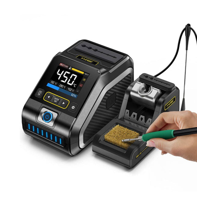
The FNIRSI DWS-200 is a powerful 200 W smart soldering station, ideal for electronic soldering applications. Powered by a switch-mode power supply, it operates smoothly with a wide voltage input range of 100-240 V. The station provides an adjustable temperature range from 100°C to 450°C (212°F to 842°F) and allows for easy switching between °C and °F.
To enhance efficiency, it supports up to three preset temperature values and can connect to a soldering iron stand for standby mode activation. The station also features a dynamic temperature curve mode for real-time data monitoring, ensuring precise and consistent performance in demanding soldering tasks.
Features
Maximum power output of 200 W, allowing for fast heating
Wide adaptive voltage input of 100-240 V
2.8" HD color TFT display with intelligent control
Multiple preset groups to switch between different settings quickly
Supports F245 and F210 soldering handle types, offering flexibility for different soldering applications
Real-time sleep mode to extend the life of the soldering tip
Multi-mode real-time monitoring for power and temperature status, enhancing safety and precision
Specifications
Peak Power
200 W (max)
Temperature Range
100°C~450°C (212°F~842°F)
Display
2.8" TFT HD Color Screen
Heating Time
1 sec
Melting Time
3 sec
Input Voltage
100-240 V (AC)
Input Fuse
3 A
Soldering Handle Type
F245
Dimensions (Station)
156 x 96 x 103 mm
Weight (Station)
475 g
Included
1x FNIRSI DWS-200 Soldering Station
1x Soldering Handle F245
6x Soldering Tips (B, KU, K, C2, I, JS)
1x Connecting Cable
2x Helping Hands
1x Power Cable (EU)
Downloads
Manual
Firmware V1.3