


This category offers a wide spectrum of platforms to choose from. They all have different features and you can choose the platform that best suits your needs or project.
Platforms
-

Elecrow Elecrow ThinkNode M5 – Meshtastic LoRa Transceiver (868 MHz)
High-Performance LoRa Communication Device The Elecrow ThinkNode M5 is a compact, portable LoRa communication device designed for off-grid messaging, location sharing, and outdoor use. Powered by an ESP32-S3 processor and an SX1262 LoRa chip, it comes pre-installed with Meshtastic firmware and can be configured conveniently via Bluetooth using the official Meshtastic app. The integrated multi-GNSS module supports GPS, GLONASS, BeiDou, and QZSS for reliable positioning and location sharing. Messages and device information are displayed on the energy-efficient 1.54-inch e-paper screen, while the built-in 1,200 mAh rechargeable battery enables extended mobile operation. With its integrated LoRa antenna, compact housing, RTC, and support for both Meshtastic and MeshCore firmware, the ThinkNode M5 is a practical communication solution for hiking, camping, remote locations, and emergency situations where conventional mobile networks are unavailable. Features LoRa communication Multi-GNSS positioning 1,200 mAh rechargeable battery 1.54-inch e-paper display Built-in RTC Compatible with MeshCore Compatible with Meshtastic Specifications Main Processor (ESP32-S3) CPU/SoC Xtensa 32-bit LX7 dual-core processor, clocked at up to 240 MHz System Memory 512 KB SRAM, 8 MB PSRAM Storage 4 MB Flash, 384 KB ROM Firmware Meshtastic firmware is fully compatible, and the signal is transmitted in LoRa mode EPD (Electronic Paper Display) Display Size 1.54 inch EPD (monochrome Ink screen) Display Materials E-lnk (Electronic Ink) Resolution 200 x 200 Driver Chip SSD1681 (via SPI or I²C interface) Global Fresh Time 2s Wireless Communication Bluetooth Bluetooth Low Energy and Bluetooth 5.0 (phone configuration) LoRa SX1262 LoRa Module, EU 868 MHz(external antenna) Hardware Interfaces USB-C, RP-SMA Function GPS Location (GPS, GLONASS, BeiDou, QZSS), EPD Display, RTC, USB 2.0, PMU power management (built-in 1200 mAh lithium battery), buzzer, etc. Button Knob Switch, Function Button, Page Turn Button, GPS Switch, Reset Button LED Indicator Power supply, GPS/LoRa indication Others Power Input 5 V/1 A, supports USB or lithium battery power supply Power consumption The maximum working current is about 340 mA (CPU + LoRa module), and the low power consumption is about 34 uA Operating Temperature -10~50°C Storage Temperature -20~60°C Relative humidity 10-95%, @ 40°C (non-condensing) Enclosure ABS Plastic Dimensions 82 x 51.6 x 26.3 mm Weight 81 g Included 1x Elecrow ThinkNode M5 1x LoRa antenna 1x USB-C cable 1x Manual Downloads Manual
€ 74,95
Members: € 67,46
-

Elecrow Elecrow AI Starter Kit for Jetson Orin Nano
All-in-One AI Learning and Development Platform for Edge Intelligence This NVIDIA Jetson-based AI Starter Kit is a versatile platform for learning, development, and hands-on experimentation in Edge AI. Designed for use with the NVIDIA Jetson Orin Nano, the kit combines an 11.6-inch IPS display, an 8-megapixel pan-tilt camera, and an AI voice interaction system. It includes 30 functional modules and 38 carefully designed Python courses that progress from beginner to advanced level. The course content covers Python fundamentals, sensor technology, AI vision, and image recognition. With step-by-step practical exercises ranging from basic programming to real-world computer vision applications, this kit provides an ideal platform for students, makers, developers, and anyone looking to explore artificial intelligence and edge computing. Please note: The NVIDIA Jetson Orin Nano is not included. Features Designed for the NVIDIA Jetson Orin Nano AI voice interaction module 8 MP camera with pan-tilt control Supports object and face tracking No soldering or complex wiring required Built-in 11.6-inch IPS display 30 functional modules 38 step-by-step Python lessons I²C, UART, and GPIO expansion interfaces Portable carrying case included Specifications Main Processor Jetson Orin Nano Number of Sensors 30 Sensor Board Design Integrated sensor board, no soldering or complex wiring required Screen 11.6-inch IPS Screen Screen Resolution 1366 x 768 Camera IMX219 8MP Expansion Interfaces 2x I²C, 1x UART, 1x IO D13, 1xIO D12 Programming Environment Based on Python Number of Tutorials 38 creative tutorials Target Audience Students, teachers, hardware enthusiasts Application Scenarios Ideal for learning AI programming, Jetson Orin Nano basics Dimensions 300 x 200 x 100 mm Module List Module Quantity Temperature & Humidity Sensor 1 pcs Button 4 pcs Ultrasonic Ranging Sensor 1 pcs Light Sensor 1 pcs Linear Potentiometer 1 pcs Buzzer 1 pcs LCD 1 pcs Infrared Remote 1 pcs Relay 1 pcs NFC 1 pcs PIR Motion Sensor 1 pcs Joystick 1 pcs 4-Digital Display 1 pcs LED 1 pcs Microphone 1 pcs Speaker 1 pair Vibration Motor 1 pcs Touch Sensor 1 pcs 8x8 RGB Matrix 1 pcs Atmospheric pressure sensor 1 pcs Tilt Switch 1 pcs Stepper Motor 1 pcs Accelerometer & Gyro 1 pcs Gas Sensor (MQ2) 1 pcs Hall Sensor 1 pcs Rotary Encoder 1 pcs U-shaped photoelectric switch 1 pcs NTC 1 pcs Servo 2 pcs Monocular camera 1 pcs Included 1x Elecrow AI Starter Kit for Jetson Orin Nano 1x IR Remote Control 1x NFC Card 1x 128 GB SD Card 1x 40-pin GPIO Cable 2x 22-pin FPC Cable 2x 24-pin FPC Cable 1x Jetson DP & USB Adapter Board Not included NVIDIA Jetson Orin Nano Downloads Manual Wiki OpenClaw Install and Config Guide
€ 249,00
Members: € 224,10
-

Elektor Bundles Physical AI with Raspberry Pi (Bundle)
This bundle combines the SunFounder AI Fusion Lab Kit with the new book Physical AI with Raspberry Pi, providing a complete hands-on introduction to AI, electronics, and Python programming. Build practical projects that combine computer vision, voice interaction, sensors, motors, and large language models. The included book guides you step by step from Raspberry Pi setup and hardware control to advanced applications using OpenCV, MediaPipe, YOLO, OpenAI services, and local Ollama models. SunFounder AI Fusion Lab Kit for Raspberry Pi The SunFounder AI Fusion Lab Kit transforms a Raspberry Pi into a complete platform for learning artificial intelligence, electronics, and Python programming. It supports Raspberry Pi 5, 4B, 3B+, 3B, and Zero 2 W, as well as popular AI models and services including ChatGPT, Gemini, Grok, DeepSeek, Qwen, Doubao, and Ollama. With its camera, Pan-Tilt HAT, 10-axis sensor module, microphone, speaker, and electronic components, the kit enables users to build interactive AI projects that combine voice, vision, movement, and sensor data. It is suitable for beginners, students, makers, and anyone who wants to explore practical AI applications. Build Multimodal AI Projects Combine large language models with speech recognition, text-to-speech, camera vision, sensors, and breadboard circuits. Create projects that can listen, speak, see, react, and interact with their environment while learning how modern AI systems work. Explore AI Vision and Object Tracking Use YOLO, OpenCV, and MediaPipe to detect and track objects, colors, faces, and human movement. The motorized Pan-Tilt HAT allows the camera to follow targets automatically, demonstrating how computer vision and motion control work together. Voice AI with the Fusion HAT+ The Fusion HAT+ simplifies hardware control through a unified Python library and supports safe Raspberry Pi shutdown. Its integrated microphone and speaker make it easy to develop voice-controlled assistants and other conversational AI applications. Compatible with Raspberry Pi 5, 4B, 3B+, 3B, and Zero 2 W Supports multiple cloud-based and local AI models Includes camera, Pan-Tilt HAT, 10DOF module, microphone, and speaker Projects covering voice AI, computer vision, sensors, and electronics Guided video lessons, documentation, and sample code Book: Physical AI with Raspberry Pi Create Intelligent Vision, Voice, and Sensor Projects Using AI Fusion Lab Kit Using the Raspberry Pi and the AI Fusion Lab Kit, this book takes you step by step from the fundamentals of hardware interfacing to the development of intelligent systems capable of seeing, listening, speaking, and making decisions. Whether you are a student, educator, maker, or professional engineer, you will gain valuable experience through projects designed to build both knowledge and confidence. Beginning with system setup, GPIO programming, sensors, displays, motors, and automation techniques, the book gradually introduces more advanced topics, including speech recognition, text-to-speech synthesis, conversational AI, object recognition, and machine learning. Along the way, you will learn how to create voice-controlled devices, intelligent assistants, camera tracking systems, environmental monitoring solutions, and AI-powered embedded applications. Explore modern technologies such as OpenAI services, Ollama local large language models, OpenCV, MediaPipe, and YOLO object detection while gaining practical experience with real-world applications used in robotics, industrial automation, smart devices, and autonomous systems. You’ll discover how intelligent software can interact with sensors, cameras, motors, and displays to create systems that respond naturally to the world around them. Rather than simply following code examples, you will be encouraged to experiment, customize, and expand every project. The techniques and skills developed throughout this book provide a solid foundation for future innovation, rapid prototyping, research, and product development. If you are ready to move beyond traditional electronics and explore the future of intelligent embedded systems, this book will guide you every step of the way. This bundle contains: SunFounder AI Fusion Lab Kit for Raspberry Pi (normal price: €100) Book: Physical AI with Raspberry Pi (normal price: €45) Not included Raspberry Pi
€ 144,95€ 129,95Best Price
-

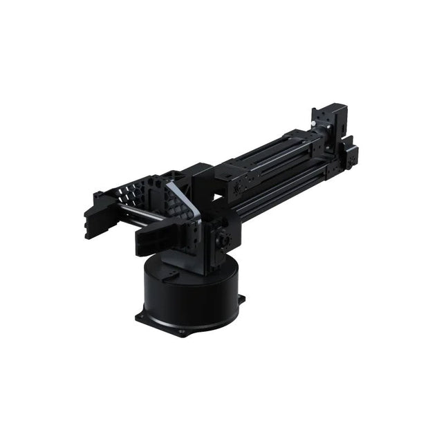
Unitree Unitree Go2 D1 Servo Robotic Arm
The Unitree Go2 D1 Servo Robotic Arm is a high-performance 6-DOF robotic arm, purpose-built for seamless integration with the Unitree Go2 Quadruped Robot. Designed for flexibility and precision, it’s an ideal tool for education, research, automation, and advanced robotics development. Featuring six fully articulated joints and an integrated gripper, the D1 offers true six-axis motion and exceptional freedom of movement. With support for position, velocity, and force control, it enables precise operation across a wide range of tasks – from real-world deployment to experimental learning environments. Constructed from lightweight aluminum alloy, the arm weighs just 2.37 kg while maintaining a reach of 670 mm. This balance of strength and agility makes it well-suited for mobile applications, without compromising stability or range. Thanks to its dual-level interface architecture, the D1 supports both low-level motor commands and high-level behavior programming – giving developers, educators, and researchers full control, whether they’re fine-tuning motion sequences or building complex robotic workflows. Compatible with external components like cameras or mobile robot chassis, the Unitree D1 opens the door to a variety of expanded use cases. Whether it's autonomous object manipulation, AI training, or hands-on robotics education, the D1 transforms any environment into a dynamic and interactive innovation platform. Specifications DoF 6 Axis + 1 Gripper Payload 500 g Arm Reach 550 mm (Gripper not included)670 mm (Gripper included) Interfaces DC5.5-2.1 (Power Supply)RJ45 (Communication)USB-C (Serial Port Debugging) Motor Type Bus Servo Power 60 W Weight 2.37 kg Joint Rotation Range J1: ±135°J2: ±90°J3: ±90°J4: ±135°J5: ±90°J6: ±135°
€ 4.599,00
Best Price
-

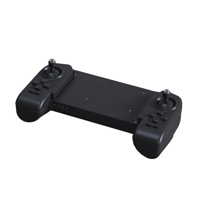
Unitree Unitree Go2 Remote Controller
The Unitree Go2 Controller is a dedicated remote control device designed for seamless and precise operation of the Unitree Go2 Quadruped Robot. This bimanual remote features built-in data transmission and Bluetooth modules, facilitating reliable wireless communication with the robot. It offers an ultra-long control distance of over 100 meters in open environments, ensuring flexibility in various operational scenarios. Specifications Charging Voltage 5 V Charging Current 2 A Frequency 2.4 GHz Communication Modes Data transmission module and Bluetooth Battery Capacity 2500 mAh Operating Time approx. 4.5 hours Control Distance Over 100 meters in open environments
€ 299,00
Best Price
-

Elektor Labs Elektor Sand Clock for Raspberry Pi Pico (incl. Laser Head Upgrade)
This bundle contains the popular Elektor Sand Clock for Raspberry Pi Pico and the new Elektor Laser Head Upgrade, offering even more options for displaying the time. Not only can you "engrave" the current time in sand, you can now alternatively write it on a glow-in-the-dark foil or create green drawings. Contents of the bundle Elektor Sand Clock for Raspberry Pi Pico (normal price: €50) Elektor Laser Head Upgrade for Sand Clock (normal price: €35) Elektor Sand Clock for Raspberry Pi (Raspberry Pi-based Eye Catcher) A standard sand clock just shows how time passes. In contrast, this Raspberry Pi Pico-controlled sand clock shows the exact time by "engraving" the four digits for hour and minute into the layer of sand. After an adjustable time the sand is flattened out by two vibration motors and everything begins all over again. At the heart of the sand clock are two servo motors driving a writing pen through a pantograph mechanism. A third servo motor lifts the pen up and down. The sand container is equipped with two vibration motors to flatten the sand. The electronic part of the sand clock consists of a Raspberry Pi Pico and an RTC/driver board with a real-time clock, plus driver circuits for the servo motors. A detailed construction manual is available for downloading. Features Dimensions: 135 x 110 x 80 mm Build time: approx. 1.5 to 2 hours Included 3x Precut acrylic sheets with all mechanical parts 3x Mini servo motors 2x Vibration motors 1x Raspberry Pi Pico 1x RTC/driver board with assembled parts Nuts, bolts, spacers, and wires for the assembly Fine-grained white sand Elektor Laser Head Upgrade for Sand Clock The new Elektor Laser Head transforms the Sand Clock into a clock that writes the time on glow-in-the-dark film instead of sand. In addition to displaying the time, it can also be used to create ephemeral drawings. The 5 mW laser pointer, with a wavelength of 405 nm, produces bright green drawings on the glow-in-the-dark film. For best results, use the kit in a dimly lit room. Warning: Never look directly into the laser beam! The kit includes all the necessary components, but soldering three wires is required. Note: This kit is also compatible with the original Arduino-based Sand Clock from 2017. For more details, see Elektor Magazine 1-2/2017 and Elektor Magazine 1-2/2018.
€ 84,95€ 69,95Best Price
-

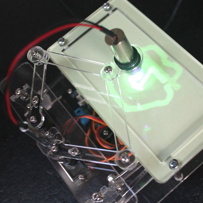
Elektor Labs Elektor Laser Head Upgrade for Sand Clock
The Elektor Laser Head transforms the Elektor Sand Clock into a clock that writes the time on glow-in-the-dark film instead of sand. In addition to displaying the time, it can also be used to create ephemeral drawings. The 5 mW laser pointer, with a wavelength of 405 nm, produces bright green drawings on the glow-in-the-dark film. For best results, use the kit in a dimly lit room. Warning: Never look directly into the laser beam! The kit includes all the necessary components, but soldering three wires is required. Note: This kit is also compatible with the original Arduino-based Sand Clock from 2017. For more details, see Elektor Magazine 1-2/2017 and Elektor Magazine 1-2/2018.
€ 34,95€ 24,95Best Price
-

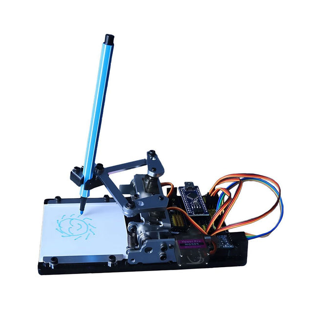
Generic Arduino-controlled Drawing Robot
This versatile plotter robot arm DIY kit for Arduino is equipped with MG90S metal gear servo motors to ensure precise and stable drawing movements. Features Fully compatible with Arduino IDE, includes complete source code for easy development and customization. Equipped with robust MG90S metal gear servo motors for accuracy and durability. Includes a Bluetooth module enabling wireless operation via a dedicated app. Specially designed robotic arm tip securely holds pens or markers with a diameter of 8-10 mm, ideal for sketches and detailed drawings. Included Arduino-compatible Nano motherboard Nano expansion board Bluetooth module MG90S all-metal gear servo motors Aluminum structural frame Thickened stable base plate Screw and fastening accessories Connecting wires USB data cable
-

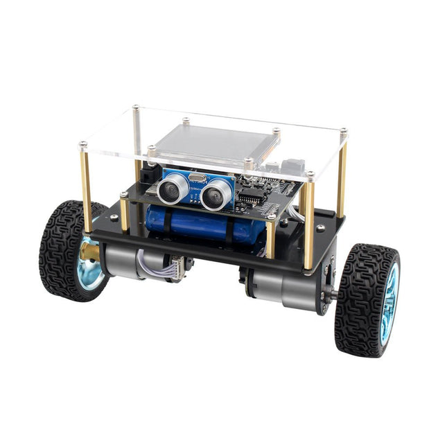
Elektor Labs Elektor Mini-Wheelie Self-Balancing Robot
Arduino-compatible, ESP32-controlled, 2-wheeled Balancing Robot The Elektor Mini-Wheelie is an experimental autonomous self-balancing robot platform. Based on an ESP32-S3 microcontroller, the self-balancing robot is fully programmable using the Arduino environment and open-source libraries. Its wireless capabilities allow it to be controlled remotely over Wi-Fi, Bluetooth or ESP-NOW or to communicate with a user or even another robot. An ultrasonic transducer is available for detecting obstacles. Its color display can be used for displaying cute facial expressions or, for the more down-to-earth users, cryptic debug messages. The robot comes as a neat kit of parts that you must assemble yourself. Everything is included, even a screwdriver. Note: The Mini-Wheelie is an educational development platform intended for learning, experimentation, and robotics development. It is not classified as a toy for children, and its features, documentation, and intended audience reflect this purpose. The product is aimed at students, educators, and developers who wish to explore robotics, programming, and hardware integration in an educational setting. Specifications ESP32-S3 microcontroller with Wi-Fi and Bluetooth MPU6050 6-axis Inertial Measurement Unit (IMU) Two independently controlled 12 V electric motors with tachometer Ultrasonic transducer 2.9" TFT color display (320 x 240) MicroSD card slot Battery power monitor 3S rechargeable Li-Po battery (11.1 V/2200 mAh) Battery charger included Arduino-based open-source software Dimensions (W x L x H): 23 x 8 x 13 cm Included 1x ESP32-S3 Mainboard + MPU6050 module 1x LCD board (2.9 inch) 1x Ultrasonic sensor 1x Battery pack (2200 mAh) 1x Battery charger 1x Motor tyre kit 1x Case board 1x Acrylic board 1x Screwdriver 1x Protective strip 1x Flex cable B (8 cm) 1x Flex cable A (12 cm) 1x Flex cable C 4x Copper column A (25 mm) 4x Copper column B (55 mm) 4x Copper column C (5 mm) 2x Plastic nylon column 8x Screws A (10 mm) 24x Screws B (M3x5) 8x Nuts 24x Metal washers 2x Zip tie 1x MicroSD card (32 GB) Downloads Documentation
-

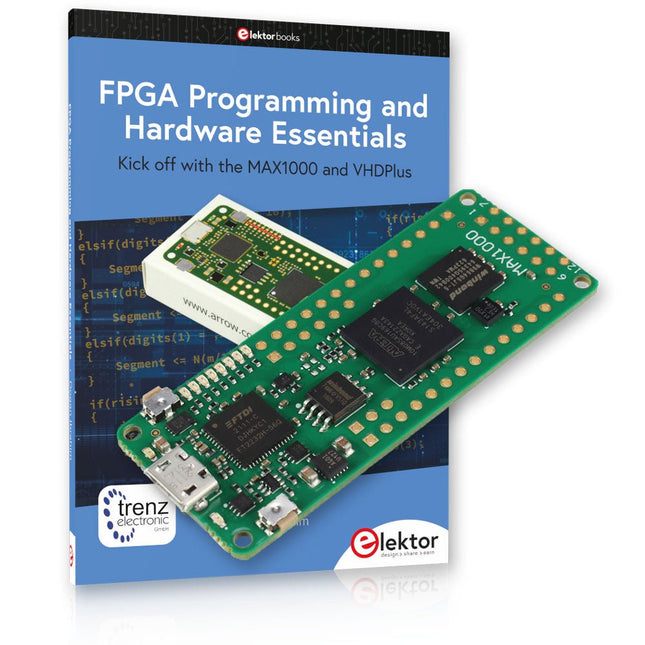
Elektor Bundles MAX1000 FPGA Programming Bundle
Kick off to FPGA Programming with the MAX1000 Board and VHDPlus Ready to master FPGA programming? With this bundle, you'll dive into the world of Field-Programmable Gate Arrays (FPGAs) – a configurable integrated circuit that can be programmed after manufacturing. Bring your ideas to life, from simple projects to complete microcontroller systems! The MAX1000 is a compact and powerful FPGA development board packed with features like memory, user LEDs, push-buttons, and flexible I/O ports. It’s the ideal starting point for anyone wanting to learn about FPGAs and Hardware Description Languages (HDLs). With the enclosed book "FPGA Programming and Hardware Essentials" you'll get hands-on with the VHDPlus programming language – a simpler version of VHDL. You'll work on practical projects using the MAX1000, helping you gain the skills and confidence to unleash your creativity. Projects in the Book Arduino-driven BCD to 7-Segment Display Decoder Use an Arduino Uno R4 to supply BCD data to the decoder, counting from 0 to 9 with a one-second delay Multiplexed 4-Digit Event Counter Create an event counter that displays the total count on a 4-digit display, incrementing with each button press PWM Waveform with Fixed Duty Cycle Generate a PWM waveform at 1 kHz with a fixed duty cycle of 50% Ultrasonic Distance Measurement Measure distances using an ultrasonic sensor, displaying the results on a 4-digit 7-segment LED Electronic Lock Build a simple electronic lock using combinational logic gates with push buttons and an LED output Temperature Sensor Monitor ambient temperature with a TMP36 sensor and display the readings on a 7-segment LED MAX1000 FPGA Development Board The MAX1000 is a customizable IoT/Maker Board ready for evaluation, development and/or use in a product. It is built around the Intel MAX10 FPGA, which is the industry’s first single chip, non-volatile programmable logic device (PLDs) to integrate the optimal set of system components. Users can now leverage the power of tremendous re-configurability paired with a high-performance, low-power FPGA system. Providing internally stored dual images with self-configuration, comprehensive design protection features, integrated ADCs and hardware to implement the Nios II 32-bit microcontroller IP, MAX10 devices are ideal solution for system management, protocol bridging, communication control planes, industrial, automotive and consumer applications. The MAX1000 is equipped with an Arrow USB Programmer2, SDRAM, flash memory, accelerometer sensor and PMOD/Arduino MKR connectors making it a fully featured plug and play solution without any additional costs. Specifications MAX 10 8 kLE - Flash Dual inside - ADC 8x 12 Bit - Temperature Range 0~85°C - Supply USB/pins SDRAM 8 MB 3-axis MEMS LIS3DH USB Programmer on board MEMS Oscillator 12 MHz Switch/LED 2x / 8x Contents of the Bundle Book: FPGA Programming and Hardware Essentials (normal price: €40) MAX1000 FPGA Development Board (normal price: €45) Downloads Software
-

Raspberry Pi Foundation Raspberry Pi AI HAT+ (26 TOPS)
The Raspberry Pi AI HAT+ is an expansion board designed for the Raspberry Pi 5, featuring an integrated Hailo AI accelerator. This add-on offers a cost-effective, efficient, and accessible approach to incorporating high-performance AI capabilities, with applications spanning process control, security, home automation, and robotics. Available in models offering 13 or 26 tera-operations per second (TOPS), the AI HAT+ is based on the Hailo-8L and Hailo-8 neural network accelerators. The 13 TOPS model efficiently supports neural networks for tasks like object detection, semantic and instance segmentation, pose estimation, and more. This 26 TOPS variant accommodates larger networks, enables faster processing, and is optimized for running multiple networks simultaneously. The AI HAT+ connects via the Raspberry Pi 5’s PCIe Gen3 interface. When the Raspberry Pi 5 is running a current version of the Raspberry Pi OS, it automatically detects the onboard Hailo accelerator, making the neural processing unit (NPU) available for AI tasks. Additionally, the rpicam-apps camera applications included in Raspberry Pi OS seamlessly support the AI module, automatically using the NPU for compatible post-processing functions. Included Raspberry Pi AI HAT+ (26 TOPS) Mounting hardware kit (spacers, screws) 16 mm GPIO stacking header Downloads Datasheet
-

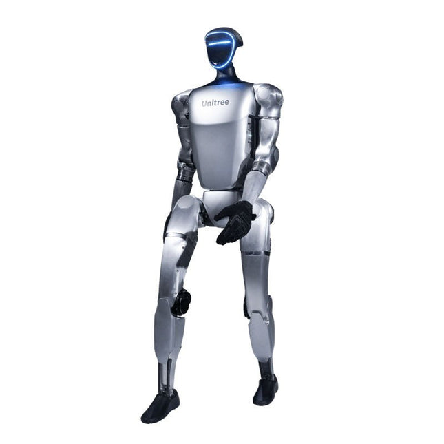
Unitree Unitree G1 Humanoid Robot
The Unitree G1 is a modern humanoid robot that impresses with its remarkable flexibility and advanced technology. With an exceptionally wide range of joint movement and up to 43 joint motors, it exceeds the agility of a typical human. Powered by imitation learning and reinforcement learning, its robotic systems are continuously developed and optimized through artificial intelligence. One of the G1's most impressive features is its ability to autonomously move into a walking position as soon as it touches the ground – no external assistance required! It can immediately start moving, demonstrating a high level of independence and adaptability. The G1 is also equipped with a force-controlled, highly dexterous hand that operates with both sensitivity and precision, thanks to its combination of force and position control. This hand closely mimics human movements, allowing for precise object manipulation. Features Intel RealSense D435 Depth Camera Livox MID-360 3D LiDAR Microphone array (noise and echo cancellation) 5 W stereo speaker Extra large quick release battery Single arm degrees of freedom (shoulder 2 + elbow 2) Hollow joint wiring of the whole machine (no external cables) Maximum torque at joints 120 N.m Single leg degrees of freedom (hip 3, knee 1, ankle 2) Moving speed of 2 m/s Specifications Height, Width and Thickness (Stand) 1320 x 450 x 200 mm Height, Width and Thickness (Fold) 690 x 450 x 300 mm Weight (with Battery) approx. 35 kg Total Degrees of Freedom(Joint Freedom 23 Single Leg Degrees of Freedom 6 Waist Degrees of Freedom 1 Single Arm Degrees of Freedom 5 Joint output bearing Industrial grade crossed roller bearings (high precision, high load capacity) Joint motor Low inertia high-speed internal rotor PMSM (Permanent Magnet Synchronous Motor – better response speed and heat dissipation) Maximum Torque of Knee Joint 90 N.m Arm Maximum Load approx. 2 kg Calf + Thigh Length 0.6 m Arm Span approx. 0.45 m Extra Large Joint Movement Space • Waist joint: Z ±155°• Knee joint: 0~165°• Hip joint: P ±154°, R -30~+170°, Y ±158° Full Joint Hollow Electrical Routing Yes Joint Encoder Dual encoder Cooling System Local air cooling Power Supply 13 string Lithium battery Basic Computing Power 8-core high-performance CPU Sensing Sensor Depth Camera + 3D LiDAR Microphones 4 Microphone Array Speaker 5 W stereo speaker Wireless WiFi 6, Bluetooth 5.2 Smart Battery (Quick Release) 9000 mAh Charger 54 V/5 A Manual Controller Yes Battery Life approx. 2 hours Upgraded Intelligent OTA Yes
€ 24.999,00
Best Price
-

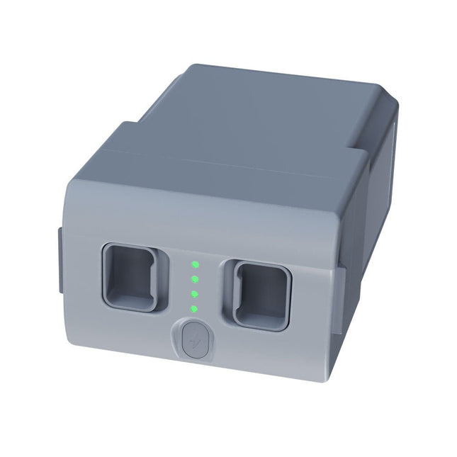
Unitree Unitree Go2 Spare Battery (15,000 mAh)
With a capacity of 15,000 mAh, the Unitree Go2 battery provides a robust power source that enables your robot to complete tasks with ease. Whether for complex exploration, research projects, or fun excursions, this powerful battery delivers the energy your robot needs. The runtime of the Unitree Go2 battery varies depending on the application and usage. Based on the functions and activities employed, the battery can offer between 2 to 4 hours of operation. This flexibility allows you to customize the robot as needed, enabling longer exploration missions or more extensive projects. The Unitree Go2 battery is a reliable companion for your robotics adventures. With its impressive capacity and adaptable runtime, it ensures your robot performs powerfully and with endurance, without frequent recharging. Whether you need the Unitree Go2 battery as a replacement or an upgrade for your robot, this powerful energy storage solution provides the perfect balance of performance and reliability. Specifications Rated voltage: DC 28.8 V Limited charging voltage: DC 33.6 V Charging current: 9 A Rated capacity: 15,000 mAh, 432 Wh Standard: IS 16046 (Part 2) / IEC 62133-2 Self-developed battery management system (BMS) Dimensions: 120 x 80 x 182 mm Functions: Power indicator Self-discharge protection of battery storage Equilibrium charge protection Overcharge protection Discharge protection Short circuit protection Battery charge detection protection
€ 795,00
Best Price
-

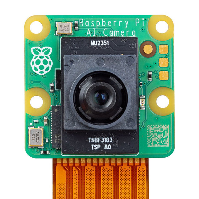
Raspberry Pi Foundation Raspberry Pi AI Camera
The Raspberry Pi AI Camera is a compact camera module based on the Sony IMX500 Intelligent Vision Sensor. The IMX500 combines a 12 MP CMOS image sensor with on-board inferencing acceleration for various common neural network models, allowing users to develop sophisticated vision-based AI applications without requiring a separate accelerator. The AI Camera enhances captured still images or video with tensor metadata, while keeping the Raspberry Pi's processor free for other tasks. Support for tensor metadata in the libcamera and Picamera2 libraries, as well as the rpicam-apps application suite, ensures ease of use for beginners while providing unparalleled power and flexibility for advanced users. The Raspberry Pi AI Camera is compatible with all Raspberry Pi models. Features 12 MP Sony IMX500 Intelligent Vision Sensor Sensor modes: 4056x3040 (@ 10fps), 2028x1520 (@ 30fps) 1.55 x 1.55 µm cell size 78-degree field of view with manually adjustable focus Integrated RP2040 for neural network and firmware management Specifications Sensor Sony IMX500 Resolution 12.3 MP (4056 x 3040 pixels) Sensor size 7.857 mm (type 1/2.3) Pixel size 1.55 x 1.55 μm IR cut filter Integrated Autofocus Manual adjustable focus Focus range 20 cm – ∞ Focal length 4.74 mm Horizontal FOV 66 ±3° Vertical FOV 52.3 ±3° Focal ratio (F-stop) F1.79 Output Image (Bayer RAW10), ISP output (YUV/RGB), ROI, metadata Input tensor maximum size 640 x 640 (H x V) Framerate • 2x2 binned: 2028x1520 10-bit 30fps• Full resolution: 4056x3040 10-bit 10fps Ribbon cable length 20 cm Cable connector 15 x 1 mm FPC or 22 x 0.5 mm FPC Dimensions 25 x 24 x 11.9 mm Downloads Datasheet Documentation
-

Velleman Whadda Electronic Dice
This electronic dice with 7 red LEDs rolls when the push button is released and works with a 9 V battery (not included). Downloads Manual
€ 6,50
-

Velleman Whadda 3D Xmas Tree Kit
The Whadda 3D Xmas Tree Kit is aimed at hobbyists and beginners who are interested in soldering and electronics. With this DIY kit, you can build a festive LED Christmas tree. Features 16 flashing red LEDs Extra green and yellow LEDs provided to customise your tree Can be hung on and fed through wires Will operate on 12 V DC (e.g. in cars) Specifications Low power consumption 8 mA Power supply 9 V battery operation (not included) Dimensions 102 x 88 x 80 mm Weight 65 g Downloads Manual
€ 10,95
-

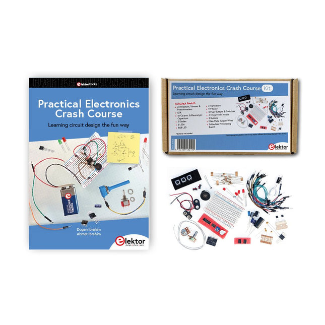
Elektor Bundles Practical Electronics Crash Course (Bundle)
Getting started in electronics is not as difficult as you may think. With this bundle (book + kit of parts), you can explore and learn the most important electrical and electronics engineering concepts in a fun way by doing various experiments. You will learn electronics practically without getting into complex technical jargon and long calculations. As a result, you will be creating your own projects soon. This kit contains the components required to build most of the detailed examples of the book on a breadboard and try them out for real. The kit can, of course, also be used without the book for building other circuits and doing your own experiments. Kit contents 1x 39 Ω, 1 W resistor 1x 47 Ω resistor 1x 180 Ω resistor 1x 330 Ω resistor 3x 1 kΩ resistor 1x 2.2 kΩ resistor 1x 3.9 kΩ resistor 1x 6.8 kΩ resistor 1x 10 kΩ resistor 1x 15 kΩ resistor 1x 22 kΩ resistor 1x 33 kΩ resistor 1x 47 kΩ resistor 1x 56 kΩ resistor 1x 82 kΩ resistor 1x 120 kΩ resistor 1x 680 kΩ resistor 2x 100 kΩ resistor 1x 10 kΩ trimmer 1x 10 kΩ linear potentiometer 1x 100 kΩ linear potentiometer 1x LDR 1x 1 nF ceramic capacitor 2x 10 nF ceramic capacitor 1x 100 nF ceramic capacitor 1x 1 µF, 25 V aluminium electrolytic capacitor 2x 10 µF, 25 V aluminium electrolytic capacitor 1x 100 µF, 25 V aluminium electrolytic capacitor 1x 470 µF, 25 V aluminium electrolytic capacitor 1x 1000 µF, 25 V aluminium electrolytic capacitor 1x RGB LED, Common-Cathode (CC) 1x 1N4148 small signal diode 1x 1N4733A 5.1 V, 1 W Zener diode 3x LED, red 2x BC337 NPN transistor 1x IRFZ44N N-channel MOSFET 2x NE555 timer 1x LM393 comparator 1x 74HCT08 quad AND gate 3x Tactile switch 2x SPDT switch 1x Relay, SPDT, 9 VDC 1x Active buzzer 1x Passive buzzer 50 cm Solid wire, 16 AWG, unjacketed 2x PP3 9 V battery clip 1x Breadboard 20x Jumper wire This bundle contains: Practical Electronics Crash Course Kit (valued at: €45) Book: Practical Electronics Crash Course (normal price: €45)
€ 89,95€ 69,95Best Price
-

Holybro Holybro QAV 250 ARF Drone Kit
The QAV250 Kit is the perfect way to get started developing on either PX4 or Ardupilot. It pairs a carbon fiber 250 racing frame and essential electronics with Pixhawk 6C mini autopilot. The kit is easy to assemble. No soldering needed. Specifications Micro Power Module (PM06 v2) Motors: 2207 KV1950 Wheelbase: 250 mm Dimensions: 198 x 235 x 70 mm Weight: 347 g Included Carbon fiber 250 airframe with hardware Micro Power Module (PM06 v2) Motors: 2207 KV1950 5' Plastic Props Fully assembled Power Management Board with ESCs (BLHeli S ESC 20A) Battery Straps Note: LiPo battery is not included.
€ 214,95
Best Price
-

Holybro Holybro X500 V2 ARF Drone Kit
The X500 V2 ARF Kit is an affordable, lightweight, and robust carbon fiber professional drone kit that is easy to assemble (less than 15 minutes). It comes with the X500 V2 Frame Kit and motors, ESCs, power distribution boards and propellers preinstalled. It is perfectly compatible with various flight controllers such as the Holybro Pixhawk series, Durandal, Pix32 V5, etc. There are numerous improvements compared the previous model. Specifications Wheelbase: 500 mm Motor mount pattern: 16x16 mm Frame body: 144x144 mm, 2 mm thick Landing gear height: 215 mm Space between top and bottom plates: 28 mm Weight: 610 g Flight time: ~18 minutes hover with no additional payload. Tested with 5000 mAh battery. Payload: 1500 g (without battery, 70% throttle) Battery recommendation: 4S 3000-5000 mAh 20C+ with XT60 Lipo battery (not Included) Included X500 V2 Frame Kit With Preinstalled Items: 4x Motors: Holybro 2216 KV920 Motor (4 pcs) with XT30 Plug 4x ESCs (BLHeli S ESC 20A) 6x 1045 Propellers Power Distribution Board – XT60 plug for battery & XT30 plug for ESCs & peripherals Note: Depth camera mount is sold separately.
€ 379,95
Best Price
-

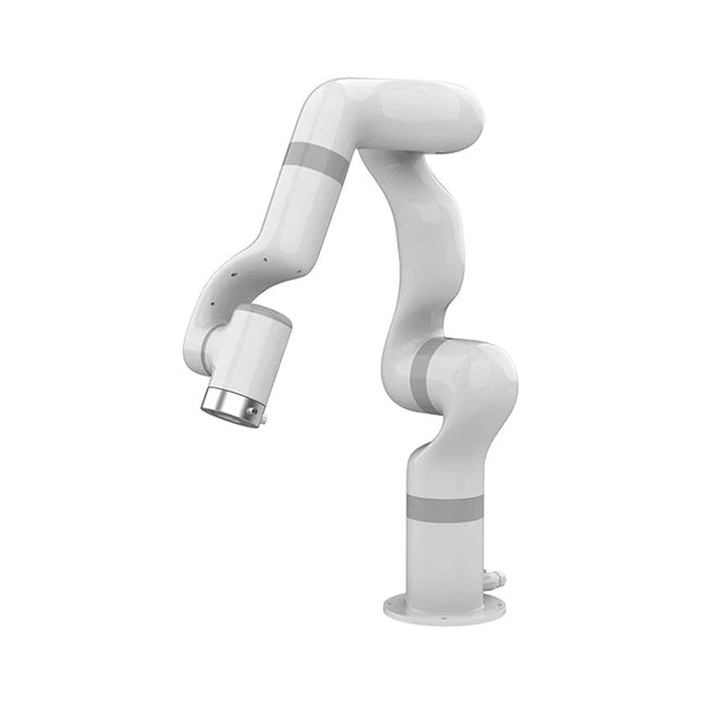
UFactory UFactory 850 Robotic Arm
UFactory 850 is the most powerful robot with industrial grade performance. Features 6DoF Payload: 5 kg Reach: 850 mm Repeatability: 0.02 mm Weight: 20 kg Applications Glambot Welding Screwdriving Robot Vision Industrial Production Designed for both mobile platforms and your workbench The AC control box contains an AC-DC adapter inside, 100-240 V AC is all ready to go. The DC control box supports 48-72 V wide inputs, it perfectly fits the battery system on your mobile platform. Flexible Deployment With Safe Feature Hand teaching, space-saving and easy to re-deploy to multiple applications without changing your production layout. Perfectly for recurrent tasks. Collision detection is available for all of our cobots. Your safety is always the top priority. Graphical Interface For Beginner-Friendly Programming Compatible with various operation systems, including macOS and Windows. Web-based technology compatible with all major browsers. Drag and drop to create your code in minutes. Powerful And Open Source SDK At Your Fingertips Fully functional open-source Python/C++ SDK provides more flexible programming. ROS/ROS2 packages are ready-to-go. Example codes help you to deploy the robotic arm smoothly. Specifications UFactory 850 xArm 5 xArm 6 xArm 7 Payload 5 kg 3 kg 5 kg 3.5 kg Reach 850 mm 700 mm 700 mm 700 mm Degrees of freedom 6 5 6 7 Repeatability ±0.02 mm ±0.1 mm ±0.1 mm ±0.1 mm Maximum Speed 1 m/s 1 m/s 1 m/s 1 m/s Weight (robot arm only) 20 kg 11.2 kg 12.2 kg 13.7 kg Maximum Speed 180°/s 180°/s 180°/s 180°/s Joint 1 ±360° ±360° ±360° ±360° Joint 2 -132°~132° -118°~120° -118°~120° -118°~120° Joint 3 -242°~3.5° -225°~11° -225°~11° ±360° Joint 4 ±360° -97°~180° ±360° -11°~225° Joint 5 -124°~124° ±360° -97°~180° ±360° Joint 6 ±360° ±360° -97°~180° Joint 7 ±360° Hardware Ambient Temperature Range 0-50°C Power Consumption Typical 240 W, max 1000 W Input Power Supply 48 V DC, 20.8 A Footprint Ø 190 mm Materials Aluminum, Carbon Fiber Base Connector Type M8x4 ISO Class Cleanroom 5 Robot Mounting Any End Effector Communication Protocol Modbus RTU End Effector I/O 2x DI / 2x DO / 2x AI / 1x RS485 Communication Mode Ethernet Included 1x UFactory 850 robotic arm 1x AC control box 1x Control box power cable
€ 11.779,00
Best Price
-

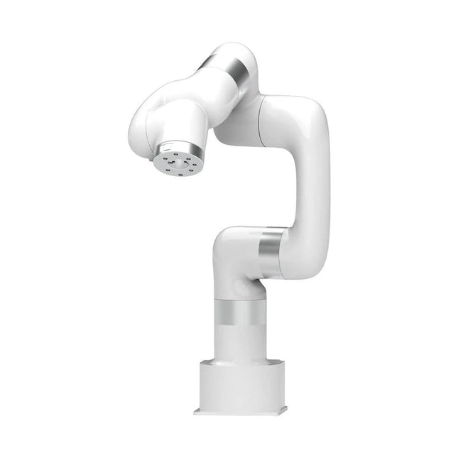
UFactory UFactory xArm 7
This multi-axis robot perfectly balances power and size. Features 6 Axis Payload: 3.5 kg Reach: 700 mm Repeatability: 0.1 mm Max Speed 1000 mm/s Applications Machine Tending Bin Picking Mobile platform Lab Automation Robotic Research Durable Collaborative robots for your automation Industrial-grade harmonic drive and servomotors guarantee 24/7 working without stop. Crafted from Carbon fiber, 15 kg weight makes it possible for easier deployment. Flexible deployment with safe feature Hand teaching, lightweight, space-saving and easy to re-deploy to multiple applications without changing your production layout. Perfectly for recurrent tasks. Collision detection is available for all of our cobots. Your safety is always the top priority. Graphical interface for beginner-friendly programming Compatible with various of operation systems, including macOS and Windows. Web-based technology compatible with all major browsers. Drag and drop to create your code in minutes. Powerful and open source SDK at your fingertips Fully functional open-source Python/C++ SDK provides more flexible programming. ROS/ROS2 packages are ready-to-go. Example codes help you to deploy the robotic arm smoothly. Specifications UFactory 850 xArm 5 xArm 6 xArm 7 Payload 5 kg 3 kg 5 kg 3.5 kg Reach 850 mm 700 mm 700 mm 700 mm Degrees of freedom 6 5 6 7 Repeatability ±0.02 mm ±0.1 mm ±0.1 mm ±0.1 mm Maximum Speed 1 m/s 1 m/s 1 m/s 1 m/s Weight (robot arm only) 20 kg 11.2 kg 12.2 kg 13.7 kg Maximum Speed 180°/s 180°/s 180°/s 180°/s Joint 1 ±360° ±360° ±360° ±360° Joint 2 -132°~132° -118°~120° -118°~120° -118°~120° Joint 3 -242°~3.5° -225°~11° -225°~11° ±360° Joint 4 ±360° -97°~180° ±360° -11°~225° Joint 5 -124°~124° ±360° -97°~180° ±360° Joint 6 ±360° ±360° -97°~180° Joint 7 ±360° Hardware Ambient Temperature Range 0-50°C Power Consumption Min 8.4 W, Typical 200 W, max 400 W Input Power Supply 24 V DC, 16.5 A Footprint Ø 126 mm Materials Aluminum, Carbon Fiber Base Connector Type M5x5 ISO Class Cleanroom 5 Robot Mounting Any End Effector Communication Protocol Modbus RTU(rs485) End Effector I/O 2x DI/2x DO/2x AI/1x RS485 Communication Mode Ethernet Included 1x xArm 7 robotic arm 1x AC control box 1x Robotic arm power cable 1x Robotic arm end effector adapter cable 1x Robotic arm signal cable 1x Control box power cable 1x Network cable 1x Mounting tool 1x Quick start guide
€ 14.569,00
Best Price
-

UFactory UFactory xArm 6
This multi-axis robot perfectly balances power and size. Features Payload: 5 kg Reach: 700 mm Repeatability: 0.1 mm Max Speed 1000 mm/s Applications Machine Tending Bin Picking Mobile platform Lab Automation Robotic Research Durable Collaborative robots for your automation Industrial-grade harmonic drive and servomotors guarantee 24/7 working without stop. Crafted from Carbon fiber, 15 kg weight makes it possible for easier deployment. Flexible deployment with safe feature Hand teaching, lightweight, space-saving and easy to re-deploy to multiple applications without changing your production layout. Perfectly for recurrent tasks. Collision detection is available for all of our cobots. Your safety is always the top priority. Graphical interface for beginner-friendly programming Compatible with various of operation systems, including macOS and Windows. Web-based technology compatible with all major browsers. Drag and drop to create your code in minutes. Powerful and open source SDK at your fingertips Fully functional open-source Python/C++ SDK provides more flexible programming. ROS/ROS2 packages are ready-to-go. Example codes help you to deploy the robotic arm smoothly. Specifications UFactory 850 xArm 5 xArm 6 xArm 7 Payload 5 kg 3 kg 5 kg 3.5 kg Reach 850 mm 700 mm 700 mm 700 mm Degrees of freedom 6 5 6 7 Repeatability ±0.02 mm ±0.1 mm ±0.1 mm ±0.1 mm Maximum Speed 1 m/s 1 m/s 1 m/s 1 m/s Weight (robot arm only) 20 kg 11.2 kg 12.2 kg 13.7 kg Maximum Speed 180°/s 180°/s 180°/s 180°/s Joint 1 ±360° ±360° ±360° ±360° Joint 2 -132°~132° -118°~120° -118°~120° -118°~120° Joint 3 -242°~3.5° -225°~11° -225°~11° ±360° Joint 4 ±360° -97°~180° ±360° -11°~225° Joint 5 -124°~124° ±360° -97°~180° ±360° Joint 6 ±360° ±360° -97°~180° Joint 7 ±360° Hardware xArm Robot specs Ambient Temperature Range 0-50°C Power Consumption Min 8.4 W, Typical 200 W, max 400 W Input Power Supply 24 V DC, 16.5 A Footprint Ø 126 mm Materials Aluminum, Carbon Fiber Base Connector Type M5x5 ISO Class Cleanroom 5 Robot Mounting Any End Effector Communication Protocol Modbus RTU(rs485) End Effector I/O 2x DI/2x DO/2x AI/1x RS485 Communication Mode Ethernet Included 1x xArm 6 robotic arm 1x AC control box 1x Robotic arm power cable 1x Robotic arm end effector adapter cable 1x Robotic arm signal cable 1x Control box power cable 1x Network cable 1x Mounting tool 1x Quick start guide
€ 11.259,00
Best Price
-

UFactory UFactory xArm 5 Lite
A multi-axis robot perfectly balances power and size Features 5 Axis Payload: 3 kg Reach: 700 mm Repeatability: 0.1 mm Max Speed 1000 mm/s Applications Machine Tending Bin Picking Mobile platform Lab Automation Robotic Research Durable Collaborative robots for your automation Industrial-grade harmonic drive and servomotors guarantee 24/7 working without stop. Crafted from Carbon fiber, 15 kg weight makes it possible for easier deployment. Flexible deployment with safe feature Hand teaching, lightweight, space-saving and easy to re-deploy to multiple applications without changing your production layout. Perfectly for recurrent tasks. Collision detection is available for all of our cobots. Your safety is always the top priority. Graphical interface for beginner-friendly programming Compatible with various of operation systems, including macOS and Windows. Web-based technology compatible with all major browsers. Drag and drop to create your code in minutes. Powerful and open source SDK at your fingertips Fully functional open-source Python/C++ SDK provides more flexible programming. ROS/ROS2 packages are ready-to-go. Example codes help you to deploy the robotic arm smoothly. Specifications UFactory 850 xArm 5 xArm 6 xArm 7 Payload 5 kg 3 kg 5 kg 3.5 kg Reach 850 mm 700 mm 700 mm 700 mm Degrees of freedom 6 5 6 7 Repeatability ±0.02 mm ±0.1 mm ±0.1 mm ±0.1 mm Maximum Speed 1 m/s 1 m/s 1 m/s 1 m/s Weight (robot arm only) 20 kg 11.2 kg 12.2 kg 13.7 kg Maximum Speed 180°/s 180°/s 180°/s 180°/s Joint 1 ±360° ±360° ±360° ±360° Joint 2 -132°~132° -118°~120° -118°~120° -118°~120° Joint 3 -242°~3.5° -225°~11° -225°~11° ±360° Joint 4 ±360° -97°~180° ±360° -11°~225° Joint 5 -124°~124° ±360° -97°~180° ±360° Joint 6 ±360° ±360° -97°~180° Joint 7 ±360° Hardware Ambient Temperature Range 0-50°C Power Consumption Min 8.4 W, Typical 200 W, max 400 W Input Power Supply 24 V DC, 16.5 A Footprint Ø 126 mm Materials Aluminum, Carbon Fiber Base Connector Type M5x5 ISO Class Cleanroom 5 Robot Mounting Any End Effector Communication Protocol Modbus RTU(rs485) End Effector I/O 2x DI/2x DO/2x AI/1x RS485 Communication Mode Ethernet Included 1x xArm 5 robotic arm 1x AC control box 1x Robotic arm power cable 1x Robotic arm end effector adapter cable 1x Robotic arm signal cable 1x Control box power cable 1x Network cable 1x Mounting tool 1x Quick start guide
€ 7.285,00
Best Price
-

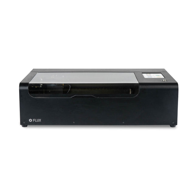
FLUX FLUX Beamo Laser Cutter
FLUX Beamo is a powerful and compact 30 W CO2 desktop laser cutter that can cut and engrave a range of materials including metals. With its easy-to-use design, intuitive controls and features, you can effortlessly create amazing things. Built-in HD camera Cutting and engraving is hassle-free with our preview mode. Place your material, preview the work area in the Beam Studio software and engrave. Your design comes out exactly as shown in the preview. Integrated safety features If left opened, auto pause ensures the laser stops. The internal water cooling system provides a stable cutting process. Plus, you can stop production with a single switch at any time. Powerful high resolution laser The Beamo ultra thin laser can engrave exceptional detail down to 0.05 mm wide with a clear resolution of 1,000 dpi. Fitting for any craft or small business project. The most precise compact CO2 laser engraver Beamo's sleek, modern and compact design fits beautifully in any home, school or workshop space. It comes pre-assembled with a metal body and acrylic lid, measuring 615 x 445 x 177 mm. Bring your designs to life with its 30 W CO2 laser operating on a 30 x 21 cm work area. Safe for home and school Beamo prioritises safety with its thoughtful design features. The machine is fully enclosed, and it automatically pauses if the lid is opened during a task. Additionally, there is a single switch for immediate machine shutdown in case of emergencies. Beamo is equipped with a Class 1 laser, which is completely safe under normal use. Specifications Dimensions 615 x 445 x 177 mm Weight 22 kg Work Area 300 x 210 x 45 mm (11.81 x 8,27 x 1.77') Camera Preview Area 300 x 195 mm Voltage AC 110 V / 220 V Touch Panel 1024 x 600 LCD Camera HD CMOS I/O Wi-Fi / Ethernet Laser Spec 30 W CO₂ Laser Laser Moving Speed 0~300 mm/s Laser Cutting Thickness 0-5 mm (varies by material) Software Mode Vector / Graphic (monochrome, gray scale) Operating System Windows / macOS / Linux Software File Type JPG / PNG / SVG / DXF Included FLUX Beamo (distilled water included) Vent hose Duct Clamp Double sided tape to align the mirror's Ethernet cable Vent Hose Double head wrench Wood piece Torx screwdriver and 2.5 mm hexagonal wrench Funnel 1x Laser Cutter Lubricant Power cord Wifi Dongle USB Beamo Manual Honey Comb Platform (30 W) Downloads Firmware
€ 2.660,00
Best Price