The FNIRSI GC-03 is a multifunctional radiation detector designed for professional nuclear radiation measurement in everyday environments such as the home, office, car, and outdoors. Equipped with a 2.4-inch high-definition color display, it provides real-time monitoring of nuclear radiation as well as electric and magnetic field strength. For added safety, the device features three alarm modes: audible alert, vibration, and visual light warning.
Features
3-in-1 Detection: Monitors electric, magnetic, and nuclear radiation with one device.
High-Precision GM Tube: Accurately detects gamma, X-rays, and hard beta radiation with low power consumption.
Real-Time Curve + 50 Alarm Records: Tracks radiation trends and stores alarm history for easy review.
Custom Triple Alarms: Supports visual, audible, and vibration alerts with adjustable thresholds.
Long Battery Life: 1500 mAh battery for extended and reliable field use.
Specifications
Nuclear Radiation
Range: 0.01μSv/h-999.99μSv/h
Accuracy: 0.01μSv/h
Electric Field
Range: 1V/m-1999V/m
Accuracy: 1V/m
Magnetic Field
Range: 0.01μT-99.99μT
Accuracy: 0.01μT
Radiation Power
0.2-1000mW/m²
Detection Radiation Type
Ionizing radiation (gamma rays, etc.)
Detector
Energy compensation GM tube (Geiger counter tube)
Dose Current Rate
0.00-10000μSv/h (10mSv/h)
Cumulative Dose Equivalent
0.00μSv-500.0mSv
Energy Range
48keV-1.5MeV ≤ ±30% (for 137Cs-)
Sensitivity
80CPM/μSv
Dose Unit
μSv/h, uGy/h, mR/h, CPS, CPM
Alarm Mode
Light, vibration, sound
Display
2.4-inch color screen
Backlight
Brightness Adjustable
Power Supply
USB-C (5 V/1 A)
Battery
1500 mAh
Languages
English, Chinese
Dimensions
138 x 63 x 32 mm
Weight
141 g
Included
1x FNIRSI GC-03 Radiation Detector
1x USB cable
1x Manual
Downloads
Manual
Firmware v1.0.4
This bundle includes the Red Pitaya STEMlab 125-14 PRO Gen 2 Starter Kit and the new book "Experimenting with Red Pitaya STEMlab Gen 2".
The Red Pitaya STEMlab 125-14 PRO Gen 2 Starter Kit is a powerful and flexible platform for signal processing, data acquisition, and electronic measurement applications. Designed for engineers, developers, researchers, and educators, this kit provides everything required to start building advanced measurement and control systems.
At the core of the kit is the STEMlab 125-14 PRO Gen 2 board, an upgraded and ultra-lightweight development platform. Powered by the Xilinx Zynq-7010 SoC with 512 MB of RAM, it combines FPGA programmability with ARM processing power to enable high-performance instrumentation and custom signal-processing solutions.
The board offers 14-bit ADC and DAC resolution, a 125 MS/s sampling rate, an input range of ±20 V, and up to 60 MHz bandwidth. Its improved low-noise analog front-end, USB-C connectivity, and compact design make it suitable for demanding applications such as RF development, radar systems, photonics research, software-defined radio (SDR), and industrial automation.
The Starter Kit includes all essential accessories for immediate use: a microSD card with preinstalled operating system, power supply, Ethernet cable for remote access, two 100 MHz oscilloscope probes, and SMA-to-BNC adapters for flexible signal connections.
The Red Pitaya STEMlab 125-14 PRO Gen 2 Starter Kit is an excellent platform for rapid prototyping, FPGA development, measurement instrumentation, and advanced electronics experimentation.
Features
14-bit ADC and DAC resolution
125 MS/s sampling rate
±20 V input range
Up to 60 MHz bandwidth
Xilinx Zynq-7010 SoC (FPGA + ARM processor)
512 MB RAM
Low-noise analog front- and back-ends
Applications
RF development and testing
Radar and wireless systems
Software-defined radio (SDR)
Photonics and optical research
Industrial automation and control systems
Signal analysis and instrumentation
Rapid prototyping of electronic measurement systems
Specifications
Processor
Dual-core ARM Cortex-A9
FPGA
AMD Xilinx Zynq-7010 SoC
RAM
512 MB (4 Gb)
Storage
microSD card (up to 32 GB)
Operating System
Linux-based Red Pitaya OS
ADC Resolution
14-bit
DAC Resolution
14-bit
Bandwidth
60 MHz (DC)
Sampling Rate
125 MS/s
Analog Input Channels
2
Analog Output Channels
2
Input Voltage Range
±1 V (LV) / ±20 V (HV)
Input Impedance
1 MΩ / 10 pF
Output Voltage Range
±1 V
Ethernet
1x Gigabit Ethernet (RJ45)
USB
2x USB-C 2.0 (for power and console)
Digital I/O
16x GPIO (3.3 V)
Communication Interfaces
I²C, SPI, UART, CAN
Power Supply
5 V/3 A via USB-C
Dimensions
106.8 x 60.0 x 17.9 mm
Included
1x Red Pitaya STEMlab 125-14 PRO Gen 2 board
2x 100 MHz oscilloscope probes
2x SMA-to-BNC adapters
1x microSD card with preinstalled OS
1x USB-C Power supply
1x Ethernet cable
Downloads
Documentation
Schematics
Book: Experimenting with Red Pitaya STEMlab Gen 2
With this new book, Red Pitaya goes beyond a versatile board. It becomes a powerful laboratory instrument for precision measurement, analysis, and control.
From the fundamentals of electronic project development, monitoring, control, and design to testing, this book walks you step-by-step through everything you need to know to harness the full potential of Red Pitaya hardware and software.
The book presents real-time, FPGA-based projects that are developed on a PC using the Vivado environment, then transferred to the Red Pitaya for execution and testing.
You will learn about enhanced performance, expanded I/O capabilities, improved FPGA features, and advanced connectivity options that open up new frontiers for precision measurement, monitoring, and control in your embedded applications.
Inside the book you will discover:
A deep dive into Red Pitaya architecture and hardware design
Electronic experiments using Red Pitaya for measurement and monitoring
Hands-on projects using the Python programming language
Practical guidance for FPGA programming using Red Pitaya
Red Pitaya FPGA projects using the Verilog HDL under Vivado IDE
Practical design of electronic projects including measurement and testing
Step-by-step examples that bridge theory and real-world implementation
Whether you are designing your own electronic circuits, developing signal analysis tools, or creating real-time control or monitoring systems, this book provides you the knowledge and confidence you need to fully learn and customize the Red Pitaya platform.
The Elektor Zener Diode Tester is essentially a constant-current source that can be switched in steps from 1 to 50 mA. It can be used to test Z-diodes up to a maximum of 54 V. Thanks to a 60-V step-up converter, the device can be powered by the usual 5 to 12 V.
The principle of this tester is straightforward. A Z-diode or other DUT (device under test, such as an LED) is biased by an adjustable current source. The voltage across the DUT can be measured with a multimeter. The voltage of most (small) Z-diodes is specified at a current of 5 mA. Depending on the application, the voltage at other currents can also be of interest. That is why six current settings are available: 1, 2, 5, 10, 20, and 50 mA. LEDs are often specified at a current of 20 mA.
What can be tested is:
Whether a Z-diode is defective (short circuit or high impedance).
Whether a Z-diode exhibits the correct Z-voltage.
How a Z-voltage changes with different currents.
What exact voltage is present at an integrated voltage reference.
Whether LEDs in a series chain differ in brightness (hence the 20 mA current).
What the current gain is for different base currents in (power) transistors.
The kit contains all parts listed in the bill of materials including PCB and enclosure.
Specifications
Supply voltage
5…12 V/2 A (USB-C)
Supply current (Itest = 50 mA)
1.1 A @ 5 V / 412 mA @ 12 V
Selectable currents
1, 2, 5, 10, 20, and 50 mA
Max. test voltage
>54 V @ Itest ≥1 mA
Max. output voltage
60 V @ Itest = 0 mA
Voltage limit at 5 V
4.5 V @ Itest = 1 mA / 5.18 V @ Itest = 50 mA
Enclosure dimensions
110 x 82 x 44 mm
PCB size
105.4 x 67.3 mm
Connections
4 mm banana sockets for multimeter
2 mm banana sockets for test clips
USB-C socket for power supply
Included
Resistors
R1 = 3.3 kΩ, 600 mW, 1%
R2 = 0.15 Ω, 1 W, 5%, LS 12.7 mm, ø 3.5 mm
R3, R8 = 180 Ω, 600 mW, 1%
R4, R6, R16 = 1 kΩ, 600 mW, 1%
R5, R19 = 47 kΩ, 600 mW, 1%
R7 = 3.9 kΩ, 1 W, 5%, LS 12.7 mm, ø 3.5 mm
R9, R10, R12 = 10 kΩ, 600 mW, 1%
R11, R13 = 100 Ω, 600 mW 1%
R14 = 249 Ω, 600 mW, 1%
R15 = 499 Ω, 600 mW, 1%
R17 = 2.49 kΩ, 250 mW, 1%
R18 = 4.99 kΩ, 250 mW, 1%
Capacitors
C1 = 470 uF / 35 V, 20%, Ir = 1.86 A, ø 12.5 mm, LS 5 mm, ESR = 0.038 Ω (Panasonic EEUTP1V471)
C2 = 1 uF / 100 V, 10%, X7R, LS 5 mm
C3 = 2.2 nF / 50 V, 10%, X7R, LS 5 mm
C4, C7 = 100 nF / 100 V, 10%, X7R, LS 5 mm
C5 = 100 uF / 100 V, 20%, ø 14 mm max., LS 5 mm
C6 = 1 nF / 100 V, 10%, X7R, LS 5 mm
Inductor
L1 = 100 uH, Irms = 2.4 A, Isat = 3.5 A, 0.09 Ω, radial, pitch 2.5/5/10 mm, ø 14 mm max. (Kemet SBC8-101-242)
Semiconductors
D1 = MUR120G, DO-41
D2, D4 = STPS3150RL, DO-201AD
D3 = Z-diode, 18 V, 1.3 W (BZX85C18)
D5 = Z-diode, 5.1 V, 0.5 W (1N5231B)
LED1 = LED in pushbutton S1
LED2 = LED, green, 3 mm
IC1 = MC34063, DIP-8
IC2 = LM4040BIZ-5.0/NOPB, TO-92 (TO-226AA-3)
IC3 = TL051CP, DIP-8
T1 = BC327.25, TO-92
T2 = STP40NF10L, TO-220
T3 = IRF9510PBF, TO-220
T4 = 2N7000, TO-92
Others
K1, K2, S1, S3 = 2-way screw terminal block, LS 3.5 mm, max. 1.5 mm²
connected to K1 = USB-C socket, 30 V/3 A, chassis mounted, wired, 9 x 16 mm
connected to K2 = Banana Connector, 2 mm, Socket, 60 VDC, Panel Mount, red (Multicomp 24.102.1)
connected to K2 = Banana Connector, 2 mm, Socket, 60 VDC, Panel Mount, black (Multicomp 24.102.2)
Test clip, red, 30 VAC/60 VDC (Hirschmann 931467101)
Test clip, black, 30 VAC/60 VDC (Hirschmann 931467100)
S1 = Pushbutton, panel mount, SPST-NO, 30 DC/100 mA, with red LED
S2 = Rotary Switch, 6 position, 2 pole, 30°, 250 V/150 mA
S3 = Toggle switch, panel mount, SPDT, solder lugs, 28 VDC
T2, T3 = Heat sink, 15°C/W, FK 214 SA-CB
Enclosure Hammond 1591XXSSBK, ABS, 110 x 82 x 44 mm
Knob for S2, round shaft 6 mm, ø 21 mm, with indicator line (Multicomp CP-LB21-6-6D)
4 x Self-tapping screw #4-1/4", carbon steel, pan head
Banana plug, red, 2 mm, 60 VDC (Multicomp 25.205.1)
Banana plug, black, 2 mm, 60 VDC (Multicomp 25.205.2)
Banana socket, black 4 mm, panel mount
Banana socket, red 4 mm, panel mount
for LED1, LED2 = Pin header, 1 x 2, vertical, pitch 2.54 mm
for LED1, LED2 = Pin socket, 1 x 2, vertical, pitch 2.54 mm
for T2, T3 = M3 screw, 10 mm, steel, pan head
2 x M3 washer, plain, steel
4 x M3 nut
for IC1, IC3 = DIP-8 socket
Wire, black, 0.25 mm² (24 AWG), stranded 14 x 0.15 mm, 1 m
Wire, red, 0.25 mm² (24 AWG), stranded 14 x 0.15 mm, 1 m
PCB 250772-1 v1.1
Links
Elektor Labs
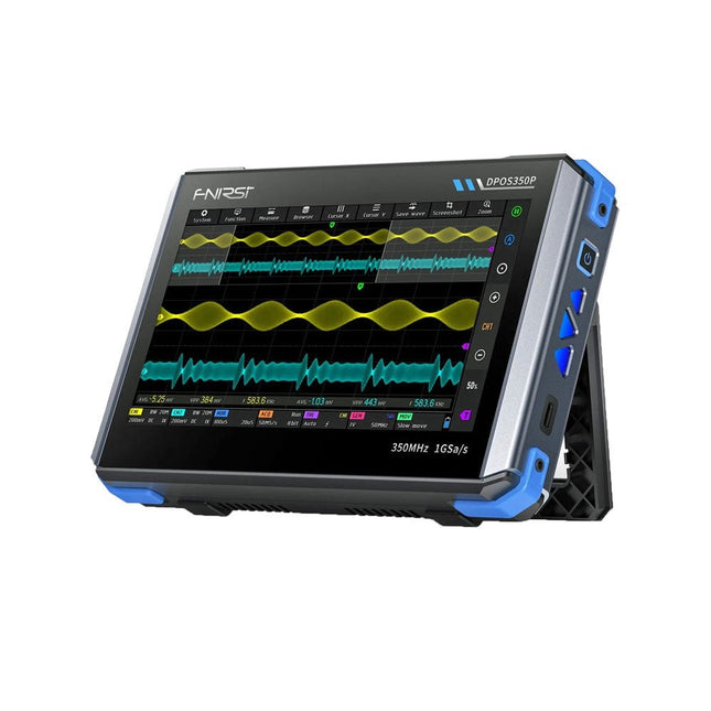
2 Channels • 350 MHz • 1 GSa/s • 50,000 wfm/s • 7 inch Touchscreen
The FNIRSI DPOS350P is a sleek 4-in-1 powerhouse in tablet form! This compact and portable device packs serious functionality: it combines a 2-channel oscilloscope (350 MHz), a signal generator (50 MHz), a frequency response analyzer (50 MHz), and a spectrum analyzer (200 kHz–350 MHz) – all in one unit.
Whether you're in R&D, troubleshooting, or field testing, the DPOS350P delivers the tools you need to measure, generate, analyze, and visualize electronic signals with precision and clarity. Its responsive high-resolution touchscreen and intuitive controls make signal analysis fast, flexible and efficient.
Features
Powerful Multi-Function Integration
350 MHz 2-channel oscilloscope with 1 GSa/s real-time sampling
50 MHz signal generator with 14 standard + custom waveforms
Spectrum analyzer (200 kHz–350 MHz): Perfect for EMI, RF & HF testing
Frequency response analyzer (FRA) up to 50 MHz
High-Performance Waveform Capture
50,000 wfm/s refresh rate for real-time signal clarity
350 MHz bandwidth (single-channel mode)
Detects rare and low-probability anomalies
Crisp Display & Smooth Operation
7" IPS touchscreen (1024 x 600 resolution)
Switch between grayscale and color temperature display
Easy to operate in various test environments
Reliable, Protected & Fast-Charging
High-voltage protection up to 400 V
Fast charging with QC 18 W (full charge in 2 hours)
Built for stable long-term operation
Data Storage & Export
Save up to 500 waveform records + 90 screenshots
USB export for easy reporting and offline analysis
Specifications
General
Display
7 inch (IPS full viewing angle)
Resolution
1024 x 600 pixels
Interaction mode
Capacitive touch screen
Total power consumption
10 W
Power-on configuration
5 presets
Charging
QC 18 W, 12 V/1.5 A (USB-C)
Battery
3.7 V, 8000 mAh lithium battery
Battery life
approx. 3 hours in operation, 5 hours standby
Heat dissipation
Air cooling
Expansion interface
USB data port
Automatic shutdown
15~60 minutes / off
Firmware upgrade
Support .iso image upgrade
Languages
English / Portuguese / Russian / Chinese
Dimensions
190 x 128 x 37 mm
Oscilloscope
Analog channels
2
Analog bandwidth
350 MHz
Rise time
1ns
Real-time sampling rate
1 GSa/s
Memory depth
60 Kpts
Input impedance
1 MΩ / 14PF
Time base range
5ns ~ 50s
Roll time base
50ms ~ 50s
Vertical sensitivity
2 mV ~ 20 V (1X)
Vertical range
16 mV ~ 160 V (1X)
DC accuracy
±2%
Time accuracy
±0.01%
Input coupling
DC / AC
Probe attenuation
1X / 10X / 100X
Hardware bandwidth limit
150M / 20M
High resolution mode
8bit ~ 16bit
Parameter measurements
12 types
Cursor measurement
Time, period, frequency, level, voltage
Trigger detection
Digital trigger
Trigger channel
CH1 / CH2
Trigger mode
Auto / Single / Normal
Trigger edge
Rising edge / Falling edge
Trigger suppression
L1 ~ L3
Trigger level
Manual / automatic 10% ~ 90%
Screenshot storage
90 pictures
Waveform storage
500 groups
Background grid
Display / hide
Waveform movement
Coarse adjustment / fine adjustment
Overvoltage protection
Withstand voltage 400 V
Waveform brightness
Adjustable
Simple FFT display
Yes
Digital fluorescence
Yes
Color temperature display
Yes
X-Y mode
Yes
ZOOM time base
Yes
One-key automatic adjustment
Yes
One-key return to zero
Yes
Data browser
Yes
Signal Generator
Waveform types
14 standard functions + captured waveform
Frequency
0~50 MHz (sine wave only, other waveforms up to 10M/5M/3M)
Amplitude
0~5 VPP
Offset
-2.5 V ~ +2.5V
Duty cycle
0.1~99.9%
Frequency resolution
1 Hz
Amplitude resolution
1 mV
Offset resolution
1 mV
Duty cycle resolution
0.1%
Customizable captured waveform
500 groups
Frequency Response Analyzer (FRA)
Excitation signal frequency
100 Hz ~ 50 MHz
Excitation signal amplitude
0~5 VPP
Excitation signal offset
-2.5V ~ +2.5V
Excitation frequency count
20~500
Cursor measurement
Frequency / gain / phase
Operating mode
Single / cyclic
System calibration
Yes
Spectrum Analyzer
Conversion method
FFT
FFT length
4K ~ 32K
Frequency range
200 KHz ~ 350 MHz
Level range
-60 dBmV ~ +260 dBmV
Cursor measurement
Frequency / amplitude
Marking parameter
Maximum energy harmonic
Waterfall chart
Yes
3D waterfall chart
Yes
Automatic adjustment
Yes
System calibration
Yes
Included
1x FNIRSI DPOS350P Oscilloscope (4-in-1)
2x 350 MHz Probes
1x QC 18 W Fast Charger (EU)
1x USB-C Cable
1x Alligator Clip
1x Storage Bag
1x Manual
Downloads
Manual
Firmware
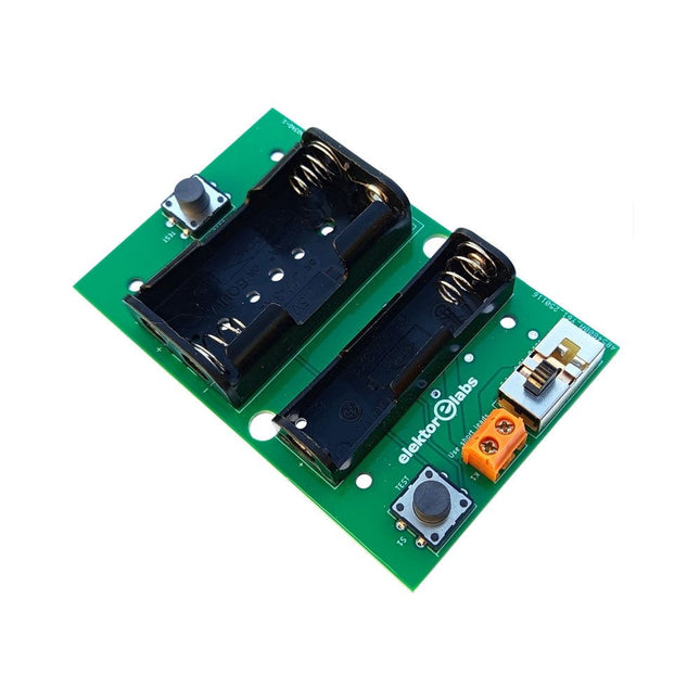
The Elektor Milliohmmeter Adapter uses the precision of a multimeter to measure very low resistance values. It is an adapter that converts a resistance into a voltage that can be measured with a standard multimeter.
The Elektor Milliohmmeter Adapter can measure resistances below 1 mΩ using a 4-wire (Kelvin) method. It is useful for locating short circuits on printed circuit boards (PCB).
The adapter features three measurement ranges – 1 mΩ, 10 mΩ, and 100 mΩ – selectable via a slide switch. It also includes onboard calibration resistors. The Elektor Milliohmmeter Adapter is powered by three 1.5 V AA batteries (not included).
Specifications
Measurement ranges
1 mΩ, 10 mΩ, 100 mΩ, 0.1%
Power supply
3x 1.5 V AA batteries (not included)
Dimensions
103 x 66 x 18 mm (compatible with Hammond 1593N-type enclosure, not included)
Special feature
On-board calibration resistors
Downloads
Documentation
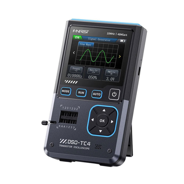
The FNIRDSI DSO-TC4 is a multifunctional transistor oscilloscope that is both comprehensive and practical. It is designed for use in maintenance and R&D applications, integrating an oscilloscope, transistor tester, and signal generator into a single device.
Features
Equipped with a 2.8-inch TFT color screen for a clear and intuitive display
Built-in high-capacity rechargeable lithium battery (1500 mAh) with a standby time of up to 4 hours
Compact and lightweight, ideal for mobile use
Specifications
Oscilloscope
Analog Bandwidth
10 MHz
Real-Time Sampling Rate
48 MSa/s
Input Impedance
1 MΩ
Coupling Mode
AC/DC
Test Voltage Range
1:1 Probe: 80 Vpp (+40 V)
10:1 Probe: 800 Vpp (+400 V)
Vertical Sensitivity
10 mV/div~10 V/div (X1 range)
Vertical Displacement
Adjustable with indication
Time Base Range
50ns~20s
Trigger Mode
Auto/Normal/Single
Trigger Type
Rising edge, Falling edge
Trigger Level
Adjustable with indication
Waveform Freeze
Yes (HOLD function)
Automatic Measurement
Max, Min, Avg, RMS, Vpp, Frequency, Cycle, Duty Cycle
Component Tester
Transistor
Amplification factor "hfe"; Base-Emitter voltage "Ube", Ic/Ie, Collector-Emitter reverse leakage current "Iceo", Ices, Forward voltage drop of protection diode "Uf"
Diode
Forward voltage drop <5 V (Forward voltage drop, Junction capacitance, Reverse leakage current)
Zener Diode
0.01~32 V
Reverse Breakdown Voltage (K-A-A Test Area)
Field-Effect Transistor (FET)
JFET: Gate capacitance "Cg", Drain current Id under "Vgs", Forward voltage drop of protection diode "Uf"
IGBT: Drain current Id under Vgs, Forward voltage drop of protection diode Uf
MIOSTET: Threshold voltage "Vt", Gate capacitance "Cg", Drain-Source resistance "Rds", Forward voltage drop of protection diode "Uf"
Unidirectional SCR
Trigger voltage <5V, Gate level (Gate voltage)
Bidirectional SCR
Trigger current <6mA (Gate voltage)
Capacitor
25pF~100mF, Capacitance value, Loss factor "Vloss"
Resistor
0.01Ω~50MΩ
Inductor
10μH~1000μH, DC resistance
DS18B20
Temperature sensor, Pins: GND, DQ, VDD
DHT11
Temperature and humidity sensor, Pins: VDD, DATA, GND
Signal Generator
Output Waveform
Supports 13 waveform outputs
Waveform Frequency
0-50 KHz
Square Wave Duty Cycle
0-100%
Waveform Amplitude
0.1-3.0 V
General
Display
2.8-inch TFT color screen
Backlight
Brightness adjustable
Power Supply
USB-C (5 V/1 A)
Battery
3.7 V/1500 mAh
Languages
English, German, Spanish, Portuguese, Russian, Chinese, Japanese, Korean
Dimensions
90 x 142 x 27.5 mm
Weight
186 g
Included
1x FNIRSI DSO-TC4 (3-in-1) Oscilloscope (10 MHz)
1x P6100 Oscilloscope probes (10X)
1x Alligator clip probe
3x Test hooks
1x Adapter
1x USB-C charging cable
1x Manual
Downloads
Manual
Firmware V0.0.7 (+V1.0.9)
The FNIRSI HRM-10 is a portable, high-precision battery internal resistance and voltage tester. This device offers true four-wire measurement and is designed for both accuracy and ease of use. It automatically measures internal resistance and voltage values simultaneously, displaying the results on its HD color screen. Users have the option to manually adjust voltage and resistance ranges to suit their needs. The device also includes a sorting mode that automatically filters the good and bad batteries based on user-set thresholds. Additionally, it supports the storage of historical data and allows for exporting measurement records in table format.
Features
High Measurement Accuracy
Tabular Data Export
Auto-Evaluate Measurement Results
8 Threshold Settings
HD Color Screen
Folding Stand
1000 mAh Lithium Battery
Specifications
Voltage
Resistance
Measuring range
0-100 V (DC)
0-200 Ω
Accuracy
±0.5%
±0.5%
Gear
Automatic, 1 V, 10 V, 100 V
Automatic, 20 mΩ, 200 mΩ, 2 Ω, 20 Ω, 200 Ω
Instrument test signal frequency
1 Khz (AC)
Rechargeable
USB-C (5 V/1 A)
Built-in battery
1000 mAh lithium battery
User calibration
Yes
Sorting mode
Yes
History record
Yes
Recorded data export
Yes
Working environment
–10°C to +45°C, relative humidity <80%
Storage environment
–20°C to +80°C, relative humidity <80%
Dimensions
158.7 x 80.5 x 28.4 mm
Weight
225 g
Included
1x FNIRSI HRM-10 Internal Resistance Tester
1x Clip Test Line
1x USB-C data cable
1x Manual
Downloads
Manual
Firmware V0.3
This highly sensitive source picoammeter is designed for measuring and logging very small currents down to the pA range – making it an ideal instrument for scientific and research applications, including physics, materials science and electron microscopy.
Full-featured at an affordable price, the SPA100 combines sensitivity, accuracy and stability to allow users to measure low currents with high precision as well as conveniently source bias voltages for experimentation. SPA100 also doubles as an ultra-high resistance meter, measuring accurately into the teraohm range.
The SPA100 connects to PC via USB and utilises the complimentary software SPA – enabling users to easily measure, graph and capture readings with timestamps and measurement stability information.
Features
Input: ±2 mA to ±200 pA in 8 ranges
Accuracy and Resolution (2 Hz):
±2 mA range: ±0.1%, resolution <20 nA
±200 uA range: ±0.1%, resolution <2 nA
±20 uA range: ±0.2%, resolution <200 pA
±2 uA range: ±0.2%, resolution <20 pA
±200 nA range: ±0.5%, resolution <2 pA
±20 nA range: ±0.5%, resolution <200 fA
±2 nA range: ±1.0%, resolution <20 fA
±200 pA range: ±1.5%, resolution <2 fA
Sample rate: 2 Hz (18 bit) or 10 Hz (16 bit)
Adjustable filter: 1 sample to 64 samples
Output voltage: -40 V to +40 V (in 1 V increments), output resistance 2.7 Kohms
Resistance Measurement: ~1 Kohms to 40 Tohms (e.g 40 V source, 1 pA measure)
Accuracy: >±0.5% 1 Mohm to 1 Tohm
Powered via USB 2.0 (instrument uses up to 0.3 A when in-use)
Included
1x SPA100 Source Picoammeter
1x USB cable
Downloads
Manual
Software
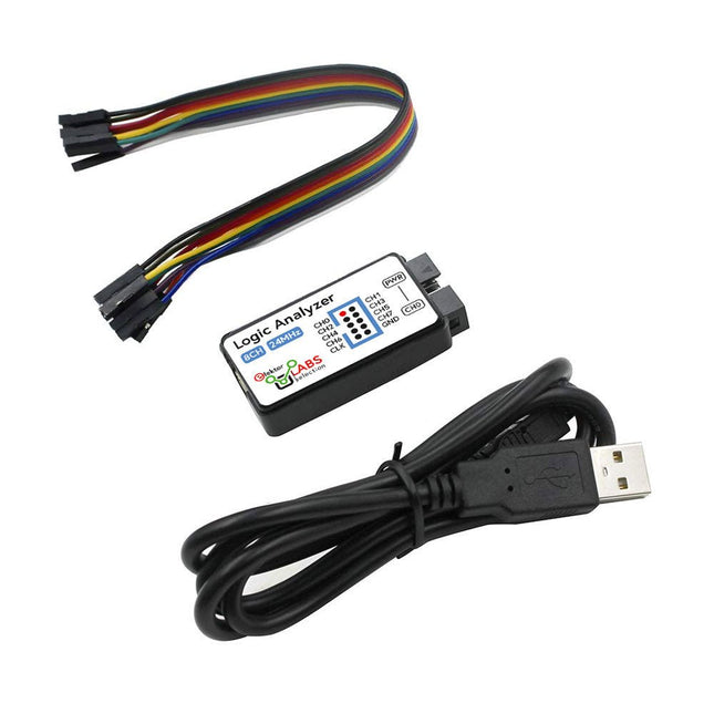
This USB Logic Analyzer is an 8-channel logic analyzer with each input dual purposed for analog data recording. It is perfect for debugging and analyzing signals like I²C, UART, SPI, CAN and 1-Wire. It operates by sampling a digital input connected to a device under test (DUT) at a high sample rate. The connection to the PC is via USB.
Specifications
Channels
8 digital channels
Maximum sampling rate
24 MHz
Maximum input voltage
0~5 V
Operating temperature
0~70°C
Input impedance
1 MΩ || 10 pF
Supported protocols
I²C, SPI, UART, CAN, 1-Wire, etc.
PC connection
USB
Dimensions
55 x 28 x 14 mm
Included
USB Logic Analyzer (8-ch, 24 MHz)
USB Cable
Jumper Wire Ribbon Cable
Downloads
Software
The QA403 is QuantAsylum's fourth-generation audio analyzer. The QA403 extends the functionality of the QA402 with improved noise and distortion performance, in addition to a flatter response at band edges. The compact size of the QA403 means you can take it just about anywhere.
Features
24-bit ADC/DAC
Up to 192 kS/s
Fully isolated from PC
Differential Input/Output
USB powered
Built-in Attenuator
Fast Bootup and Driverless
The QA403 is a driverless USB device, meaning it’s ready as soon as you plug it in. The software is free and it is quick and easy to move the hardware from one machine to the next. So, if you need to head to the factory to troubleshoot a problem or take the QA403 home for a work-from-home day, you can do it without hassle.
No-Cal Design
The QA403 comes with a factory calibration in its flash memory, ensuring consistent unit-to-unit performance. On your manufacturing line you can install another QA403 and be confident what you read on one unit will be very similar to the next unit. It is not expected that re-calibration will be required at regular intervals.
Measurements
Making basic measurements is quick and easy. In a few clicks you will understand the frequency response, THD(+N), gain, SNR and more of your device-under test.
Dynamic Range
The QA403 offers 8 gain ranges on the input (0 to +42 dBV in 6 steps), and 4 gain ranges on the output (-12 to +18 dBV in 10 dB steps). This ensures consistent performance over very wide ranges of input and output levels. The maximum AC input to the QA403 is +32 dBV = 40 Vrms. The maximum DC is ±40 V, and the maximum ACPEAK + DC = ±56 V.
Easy Programmability
The QA403 supports a REST interface, making it easy to automate measurements in just about any language you might anticipate. From Python to C++ to Visual Basic—if you know how to load a web page in your favorite language, you can control the QA403 remotely. Measurements are fast and responsive, usually with dozens of commands being processed per second.
Isolated and USB Powered
The QA403 is isolated from the PC, meaning you are measuring your DUT and not chasing some phantom ground loop. The QA403 is USB powered, like nearly all our instruments. If you are setting up remotely, throw a powered hub in your bag and your entire test setup can be running with a minimum of cables.
Goodbye Soundcard, Hello QA403
Tired of trying to make a soundcard work? The calibration nightmare? The lack of gain stages? The limited drive? Are you tired of dealing with the fixed input ranges? The worry that you might destroy it with too much DC or AC? Tired of the ground loops? That’s why QuantAsylum built the QA403.
Specifications
Dimensions
177 x 44 x 97 mm (W x H x D)
Weight
435 g
Case Material
Powder-coating Aluminum (2 mm thick front panel, 1.6 mm thick top/bottom)
Downloads
Datasheet
Manual
GitHub
The FNIRSI FNB58 USB tester (with Bluetooth) is a comprehensive and very accurate USB voltage and current meter. It features a 2.0-inch full-color HD TFT display, built-in USB-A, micro USB and USB-C interface. With this device you can measure the power supply or power consumption of products or the charging power of cell phones and power supplies. You can also determine the fast charging protocol of chargers.
Features
USB-A and USB-C interface
2.0" HD display
Data at a glance
Wide compatibility
Ultra-precise data detection
Play with fast charging technology
Automatic protocol detection (PD2.0, 3.0, 3.1, PPS, QC2.0, 3.0, FCP, SCP, AFC, PE, DASH VOOC, SuperVOOC and more)
Simple user interface, easy to operate
4 function curve displays (real-time voltage and current curve, offline curve recording, D+/D- voltage curve, high-speed power supply ripple measurement)
Cable detection
10 groups of energy recording battery capacity calculation
PC connectivity for data logging and firmware updates
Bluetooth app for Android devices
Specifications
Voltage range
4-28 V
Current range
0-7 A
Power range
0-120 W
Load equivalent internal resistance
0-9999.9 Ω
D+/D- voltage
0-3.3 V
Capacity
0-9999.99 Ah
Power consumption
0-9999.99 Wh
Cable resistance
0-9999.9 Ω
Interfaces
micro USB, USB-A, USB-C
Dimensions
42 x 13 x 82 mm
Downloads
Manual
Firmware V0.68
Measuring conducted emission is the simplest and most affordable method of getting some indication of whether a design can meet EMI/EMC requirements. A Line Impedance Stabilization Network (LISN) is an indispensable part of an EMC pre-compliance test setup.
In cooperation with Würth Elektronik, Elektor has developed a 5 µH, 50 Ω Dual DC LISN that supports voltages up to 60 V and currents up to 10 A.
The instrument measures RF interferences on both channels (the power supply) by means of 5-μH blocking inductances. The internal 10-dB attenuation network – one in each channel – contains a 3rd-order high-pass filter with a cutoff frequency of 9 kHz to protect the input of instruments like a spectrum analyzer from potentially harmful DC voltages or low frequencies coming from the EUT (Equipment Under Test).
Specifications
RF path
Channels
2 (with clamping diodes)
Bandwidth
150 kHz – 200 MHz
Inductance
5 μH || 50 Ω
Internal attenuation
10 dB
Connectors
SMA
DC path
Max. current
< 10 ADC
Max. voltage
< 60 VDC
DC resistance
< 2 x 70 mΩ
PCB size
94.2 x 57.4 mm
Connectors
4-mm banana
Hammond enclosure
Type
1590N
Dimensions
121 x 66 x 40 mm
Included
1x 4-layer PCB with all SMT parts fitted
1x pre-drilled enclosure with ready-printed front panel layout
5x gold-plated, insulated, 4-mm banana sockets, rated for 24 A, 1 kV
1x Hammond enclosure 1590N1, Aluminum (Die-Cast Alloy)
More Info
Project on Elektor Labs: Dual DC LISN for EMC pre-compliance testing
Elektor 9-10/2021: EMC Pre-Compliance Test for Your DC-Powered Project (Part 1)
Elektor 11-12/2021: EMC Pre-Compliance Test for Your DC-Powered Project (Part 2)
The Seeed Studio RF Explorer WSUB1G+ is a powerful, high-performance digital spectrum analyzer covering frequencies from 50 kHz to 1 GHz. The Slim model features a robust design, a more conveniently positioned USB connector on the side, and a larger internal battery capacity.
Features
Internal LNA amplifier and selectable attenuator
Low frequency support from 50 KHz covering LF, MF, HF, VHF and UHF up to 960 Mhz
New HELP and SET buttons to improve user interface and configuration selection with 2-clicks
Wide band coverage to all popular sub-1 Ghz bands, including FM, TV and DTV, ISM, RFID, GSM, etc.
Ideal choice for HAM bands from 160 m to 33 cm
Pocket size and light weight
Solid metal case
Spectrum Analyzer mode with Peak Max and Hold, Normal, Overwrite and Averaging modes
High capacity internal Lithium battery for 20hs+ of continuous run, rechargeable by USB
Multi-platform Windows/Linux/MacOS Open Source software and API libraries
Can be extended with internal Expansion Modules for additional band and functionality
Specifications
Frequency band: 0.05 MHz – 960 MHz
Frequency span: 0.1 MHz – 960 MHz
Internal selectable LNA 25 dB gain
Internal selectable Attenuator 30 dB
Graphics LCD 128 x 64 pixels, great visibility outdoors
Support included for Windows, Linux and MacOS X
Backlight for great visibility indoor
Internal Lithium Ion 1800 mA/h rechargeable battery
Standard SMA 50 Ω connector
Wideband 144/433 MHz dual band telescopic antenna included
UHF 400-900 MHz rubber duck articulated antenna included
Amplitude resolution: 0.5 dBm
Dynamic range: -125 dBm to 10 dBm
Absolute Max input power: +30 dBm
Average noise level (typical LNA): -125 dBm
Frequency stability and accuracy (typical): ±10 ppm
Amplitude stability and accuracy (typical): ±2 dBm
Frequency resolution: 1 kHz
Resolution bandwidth (RBW): Automatic 2.6 kHz to 600 kHz
Included
1x Seeed Studio RF Explorer WSUB1G+ Slim Spectrum Analyzer
1x Mini USB cable
1x Dual band 144/430 MHz Telescopic antenna
1x UHF 400-900 Mhz antenna
1x EVA case
The Seeed Studio RF Explorer 3G Combo is a handheld digital spectrum analyzer and an affordable tool for working across a wide range of popular frequency bands. It is based on a highly integrated frequency synthesizer and a double-balanced mixer, providing high performance, compact dimensions, low power consumption, and excellent value.
Designed for both indoor and outdoor use, the RF Explorer 3G Combo can also be connected to a PC via a standard Mini-USB 2.0 connector for additional functionality.
This model combines a WSUB1G base unit with an RFEMWSUB3G expansion module, supplied fully assembled and tested. It features two SMA connectors and includes two antennas: a dual-band 144/430 MHz telescopic antenna for sub-GHz frequencies and a helical whip antenna for the 2.4 GHz band. Additional frequency-specific antennas may be required for optimal performance in certain supported frequency ranges.
This combination provides the wide frequency coverage of the WSUB3G module together with the high sensitivity and fast response of the WSUB1G unit in the commonly used sub-1 GHz frequency range.
Features
Pocket size and light weight
Solid aluminum metal case
Includes a transport EVA carry case for RF Explorer
Spectrum Analyzer mode with Peak Max and Hold, Normal, Overwrite and Averaging modes
Lifetime free firmware upgrades available, open to community requested features
High capacity Lipo for 16+ hours of continuous run, rechargeable by USB
Windows PC client Open Source
Can be extended with internal Expansion Modules for additional band and functionality
Wide band coverage to all popular RF frequencies, starting at 15 MHz and going up to 2.7 GHz. This includes very interesting frequency areas such as 2 m HAM radio, all VHF and UHF, FM radio, GPS, WiFi and WiMax, Bluetooth, etc.
Firmware: RF Explorer 3G Combo is delivered with upgraded firmware v1.09. Note some of the features and operation accuracy will be improved in upcoming free firmware revisions.
Specifications
Battery
Lithium Cells / Batteries contained in equipment UN3481 - PI967
Frequency band
15-2700 MHz
Frequency span
112 KHz - 600 MHz
Graphics LCD
128 x 64 pixels, great visibility outdoors
PC Windows client
Supports Windows (32 and 64 bits)
Backlight
For great indoor visibility
2 standard SMA 50 ohms connector,
One for Sub-GHz wideband Nagoya NA-773 telescopic antenna included and another 2.4 GHz one for 15-2700 MHz band with helical antenna included.
Amplitude resolution
0.5 dBm
Dynamic range
Left SMA port (WSUB1G)
-115 dBm to 0 dBm
Right SMA port (WSUB3G)
-110 dBm to -10 dBm
Absolute Max input power
Left SMA port (WSUB1G)
+5 dBm
Right SMA port (WSUB3G)
+30 dBm
Average noise level (typical)
-110 dBm
Frequency stability and accuracy (typical)
±10 ppm
Amplitude stability and accuracy (typical)
±6 dBm
Frequency resolution
1 KHz
Resolution bandwidth (RBW)
Automatic 3 KHz to 600 KHz
Weight
185 g
Dimensions
113 x 70 x 25 mm
Included
Seeed Studio RF Explorer 3G Combo Spectrum Analyzer
Nagoya NA-773 wideband telescopic antenna
2.4 GHz band antenna
EVA Case
Documentation
For more info and to get started with your RF Explorer, visit the start page.
For questions and support, please visit https://support.rf-explorer.com
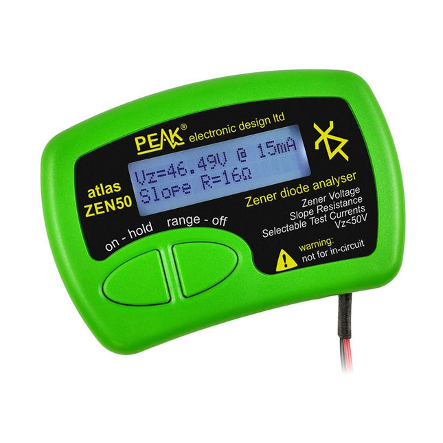
The Peak Atlas ZEN50 is ideal for testing Zener diodes (including avalanche diodes), transient suppressors, LEDs and LED strings. It generates constant current pulses (selectable from 2 mA, 5 mA, 10 mA and 15 mA) at voltages from 0 V to 50 V. So even high voltage Zeners or high voltage LED strings can be tested.
Test currents are supplied in narrow pulses to ensure that the component under test remains at a constant temperature.
The voltage of the part is displayed on the screen together with the test current and also a measure of the component's slope resistance (also known as dynamic impedance).
Specifications
Analyzer type
Zeners, LEDs, TVS etc
Test currents
2 mA, 5 mA, 10 mA, 15 mA
Voltage range
0.00 to 50.00 V
Slope resistance range
0 to 8000 Ohms
Battery type
Single AAA (supplied). Life typically 1400 ops
Test method
Triple pulse burst @ 10pps (typ)
Test current duty cycle
3%
Display type
Alphanumeric LCD (with backlight)
Included
Peak Atlas ZEN50 Zener Diode Analyzer
Fitted flexible test leads with gold plated crocs
Comprehensive illustrated user guide
AAA Alkaline battery
Downloads
Datasheet (EN)
User Guide (EN)
User Guide (FR)
User Guide (DE)
User Guide (IT)
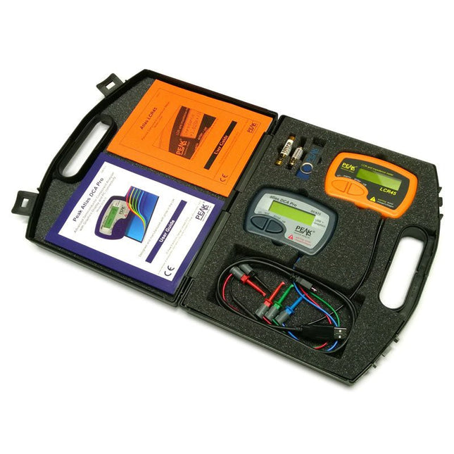
This pack contains the LCR45 Passive Component Impedance Meter, great for advanced hobbyists and professionals. It also contains the very popular DCA Pro (model DCA75), fantastic for component identification, pinout identification, detailed characteristic measurement and curve tracing on a PC. Complete with USB cable and software on a USB flash drive.
DCA75
Building on the continued success of Peak's existing component identification and analysis instruments, the DCA Pro brings an array of exciting new features for the hobbyist and professional alike.
The DCA Pro is an advanced new design that features a graphics display, USB communications, PC Software and an enhanced component identification library.
Automatic component type identification
Automatic pinout identification (connect any way round)
The DCA Pro supports all the components that the popular Peak Atlas DCA55 supports, but adds plenty more. Components supported include:
Transistors (including Darlingtons), Silicon and Germanium types. Measures gain, Vbe and leakage
MOSFETs, enhancement mode and depletion mode types. Measure on-threshold (at 5 mA) and approx transconductance (for span of 3-5 mA)
JFETs, including normally off SiC types. Measures pinch-off voltage (at 1 uA) and approx transconductance (for span of 3-5 mA)
IGBTs (insulated gate bipolar transistors). Measures on-threshold (at 5 mA)
Diodes and Diode networks
LEDs and bicolour LEDs (2 lead and 3 lead types)
Zener Diodes with measurement of zener voltage up to 9 V at 5 mA
Voltage regulators (measures regulation voltage, drop-out voltage, quiescent current)
Triacs and Thyristors that require less than 10 mA of gate current and holding current
Stand-alone or with a PC
The instrument can be used stand-alone or connected to a PC. Either way, the DCA Pro will automatically identify the component type, identify the pinout and also measure a range of component parameters such as transistor gain, leakage, MOSFET and IGBT threshold voltages, pn characteristics and much more.
Curve Tracing
When connected to a PC using the supplied USB cable, a range of low current curve-tracing functions can be performed. Various graph types are available, with more to follow:
Bipolar transistor output characteristics, IC vs VCE
Bipolar transistor gain characteristics, HFE vs VCE
Bipolar transistor gain characteristics, HFE vs IC
MOSFET and IGBT output function, ID vs VDS
MOSFET and IGBT transfer function, ID vs VGS
JFET output function, ID vs VDS
JFET transfer function, ID vs VGS
Voltage regulator, VOUT vs VIN
Voltage regulator, IQ vs VIN.
PN junction I/V curves, forward and reverse options (for Zener diodes)
Curve tracing is performed using test parameters in the range of +/-12 V or +/-12 mA. All curve-tracing data can be instantly pasted into Excel for further graphing and analysis. PC Software is included with the DCA Pro on a Peak USB memory stick. Software designed for Windows 7 and higher (all 32 or 64 bit).
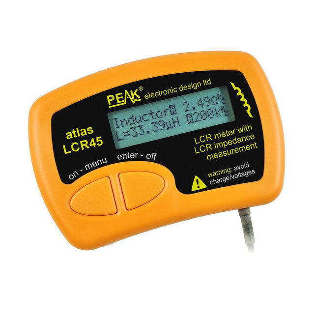
LCR45
A great handheld LCR analyzer that can measure the value of your passive component (inductor, capacitor or resistor) and also measure the detailed impedance in a number of modes. The LCR45 offers enhanced measurement resolution (better than 0.1 uH!) whilst also giving you continuous fluid measurements. Additionally, the test frequencies of DC, 1 kHz, 15 kHz and 200 kHz can be set to automatic or manual modes. Supplied with removable gold plated hook probes, battery and user guide. Compatible with standard 2 mm test connectors. Not designed for in-circuit use.
Automatic or manual component type selection: Inductor, Capacitor or Resistor
Automatic or manual test frequency selection: DC, 1 kHz, 15 kHz and 200 kHz
Inductance from 0.1 uH to 10 H
Capacitance from 0.1 pF to 10,000 uF
Resistance from 0.1 Ohm to 2 MOhm
Inductance measurement also shows DC winding resistance
Display of "Component type and values", "Complex Impedance", "Magnitude/Phase" and "Admittance"
Test frequency displayed for all measurements
Typical accuracy of 1.5% for inductors and capacitors (see spec table for details)
Typical accuracy of 1% for resistors
Test lead complete with gold plated 2 mm plugs and sockets
Supplied with removable gold plated hook probes
Included
LCR45
DCA75
Extra GP23 Battery
Extra AAA cell
Dual Carry Case
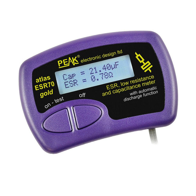
The Peak Atlas ESR70 gold is an enhanced version of the previous Peak Atlas ESR70 Plus. It does everything that the ESR70 Plus did but better.
It now measures capacitance up to 10x faster, and over a wider range, thanks to new test algorithms. The capacitance measurement is also much less influenced by parallel resistances or leakage current thanks to our new Triple-Slope measurement system.
Using the supplied gold plated probes (removable), the Atlas ESR70 gold can measure ESR down to a resolution of 0.01 ohms, up to 40 ohms. It can even measure ESR for capacitors that are in-circuit. Probes are removable, allowing 2 mm compatible probes to be fitted. Audible alerts are produced for various ESR levels allowing you to perform many tests in succession without having to look at the display. The ESR70 automatically takes capacitive reactance into account, so even low value capacitors (down to 0.3 uF) can have the ESR measured accurately.
Features
Uses a single AAA Alkaline cell (included)
Alphanumeric LCD with backlight
Automatic analysis-start when you apply the probes
Automatic capacitor discharge using controlled discharge function
ESR (and low DC resistance) measurement (even in-circuit)
Capacitive reactance automatically taken into account to ensure accurate ESR
Capacitance measurement (if testing out-of-circuit)
Audible alerts for various ESR levels
Extended ESR measurement range up to 40 Ohms
Optional probe alternatives easily fitted
New gold Features
Improved LCD with better backlight
10x faster capacitance measurement for large capacitors
Enhanced user options system
New triple-slope measurement system to vastly reduce the influence of parallel resistance and/or leakage current on capacitance measurements
Much wider capacitance measurement range now 0.3 uF to 90,000 uF (was 1uF to 22,000uF)
Specifications
Analyzer type
ESR and Capacitance
Component types
Capacitors (>0.3 uF)
ESR range
0.00 Ohms to 40.0 Ohms
ESR resolution
From 0.01 Ohms
In-circuit use
ESR only
Capacitance range
0.3 uF to 90000 uF
Battery type
1.5 V Alkaline AAA Cell (supplied). Life typically 1500 ops
Display type
Alphanumeric LCD (with backlight)
Included
Peak Atlas ESR70 gold
Extra-long and extra-flexible test cables (450 mm of Silicone covered cable)
2 mm gold plated plugs and sockets with removeable gold plated crocodile clips
Comprehensive illustrated user guide
AAA Alkaline cell
Downloads
Datasheet (EN)
User Guide (EN)
User Guide (FR)
User Guide (IT)
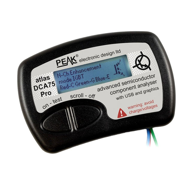
The DCA75 Pro is a great instrument that combines ease-of-use with amazing features. It can automatically identify a huge range of semiconductors, automatically identify pinouts and measure detailed parameters.
Features
Built-in graphics display (now backlit) to show detailed schematic of the component you're testing as well as pinout and measurement data
USB connectivity to allow curve tracing, data storage/retrieval and device matching on your Windows PC (Windows 7 and higher)
Single internal AAA alkaline cell for standalone operation
Component Support
Bipolar transistors (NPN/PNP inc Silicon/Germanium)
Darlington transistors (NPN/PNP)
Enhancement mode MOSFETs (N-Ch and P-Ch)
Depletion mode MOSFETs (N-Ch and P-Ch)
Junction FETs (N-Ch and P-Ch). Both symmetrical and asymmetrical types
Enhancement IGBTs (N-Ch and P-Ch)
Diodes and diode networks (2 and 3 lead types)
Zener diodes (up to about 9 V)
Voltage regulators (up to about 8 V)
LEDs and bi-colour LEDs (2 lead and 3 lead types)
Low power sensitive Triacs and Thyristors (<10 mA trigger and hold)
Measurements
BJT current gain (hFE)
BJT base emitter voltage (Vbe)
BJT collector leakage current
MOSFET on and off gate threshold voltages
MOSFET transconductance
JFET pinch-off voltage
JFET transconductance
JFET IDSS (drain current for Vgs=0)
IGBT on and off gate threshold voltages
IGBT transconductance
Voltage regulator output voltage
Voltage regulator quiescent current consumption
Voltage regulator drop-out voltage
Zener voltage
Diode forward voltage drop
Specifications
Analyzer type
Semiconductor components
Component detection
Automatic
Pinout detection
Automatic, connect any way round
Display type
Graphic LCD (now backlit)
Interface type
USB for optional PC connection
PC functions
Curve tracing (Windows 7 and higher)
Software
Included on USB drive for Windows 7 and higher
Battery
Single AAA cell (supplied)
Included
Peak Atlas DCA75 Pro
PC software on a USB Flash Drive for Windows 11, 10, 8, 7, XP
Micro USB cable
Fitted universal premium hook probes
AAA Alkaline battery
Downloads
Datasheet (EN)
User Guide (EN)
User Guide (IT)
Software Installation Guide (EN)
Software and Firmware Package
The Peak Atlas LCR45 does everything that the popular LCR40 does, but it has some significant enhancements. The LCR45 features a new high capacity micro and high resolution ADCs.
LCR45 incorporates advanced maths, based on Complex Impedance analysis. This allows for enhanced component value measurement as well as a comprehensive and detailed impedance display.
Features
Supplied with gold plated removable hook probes
Fluid measurements with hold function
Automatic or manual component type
Automatic or manual test frequency, DC, 1 kHz, 15 kHz or 200 kHz
Enhanced measurement resolution: 0.2 µH, 0.2 pF and 0.2 Ohms
Easy menu system for user settings
Enhanced compensation for component parasitics and losses (such as core losses etc)
Automatic or manual power-off
Specifications
Analyser type
LCR and component impedance
Component types
Auto/Manual for L,C & R
Measurement types
Inductance, Capacitance and Resistance
Other measurements
Complex impedance/admittance
More measurements
Magnitude and Phase of impedance
Inductance range
0uH to 2H
Capacitance range
0 pF to 10000 uF
Resistance range
0R to 2MR
Test frequency
Auto and manual: DC, 1 kHz, 15 kHz, 200 kHz
Display type
Alphanumeric LCD (not backlit)
Measurement scheme
Continuous (with optional hold)
Battery
GP23 (12 V/55 mAH type), ~700 ops
Included
LCR45 Passive Component Impedance Meter
2 mm plugs and sockets and removeable hook probes
Comprehensive illustrated user guide
2 Batteries, one installed and one spare. GP23 Alkaline battery. (12 V/55 mAH)
Downloads
Datasheet (EN)
User Guide (EN)
User Guide (FR)
User Guide (IT)
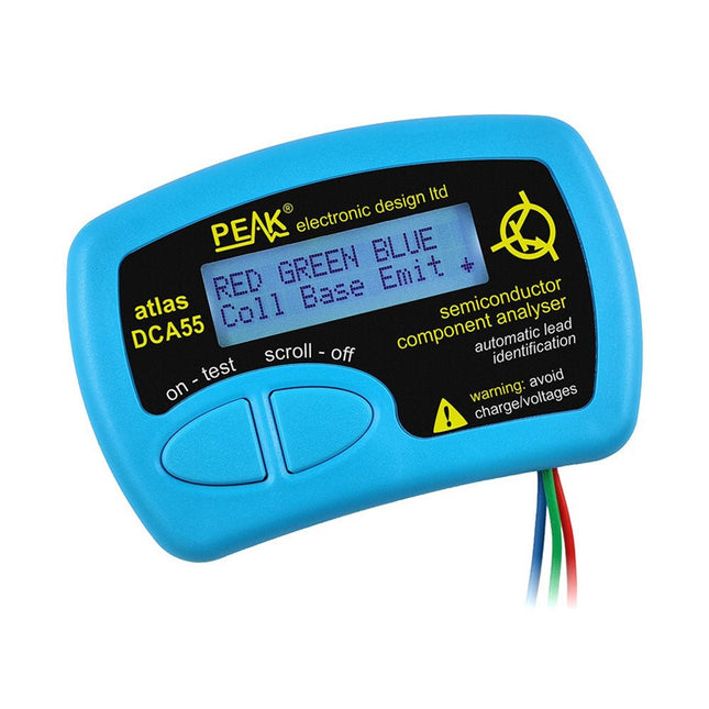
The Peak Atlas DCA55 is great for automatically identifying the type of semiconductor on the test leads as well as the pinout and many other parameters.
Supports transistors MOSFETs, JFETs (gate pin only can be identified), diodes, LEDs and lots more. Automatically identifies type of component, pinout and other important parameters. Now features transistor leakage measurement and Germanium/Silicon identification.
Component Support
Bipolar transistors (NPN/PNP inc Silicon/Germanium)
Darlington transistors (NPN/PNP)
Enhancement mode MOSFETs (N-Ch and P-Ch)
Depletion mode MOSFETs (N-Ch and P-Ch)
Junction FETs (N-Ch and P-Ch). Only gate lead identified
Diodes and diode networks (2 and 3 lead types)
LEDs and bi-colour LEDs (2 lead and 3 lead types)
Low power sensitive Triacs and Thyristors (<5 mA trigger and hold)
Measurements
Part type identification
Pinout identification
BJT current gain (hFE)
BJT base emitter voltage (Vbe)
BJT collector leakage current
MOSFET gate threshold voltage
Diode forward voltage drop (Vf)
Specifications
Analyzer type
Transistors, Diodes, LEDs, MOSFETs, JFETs
Pinout detection
Full pinout (only Gate on JFETs)
Pinout configuration
Connect any way round
Transistor measurements
Vbe, hFE, Iceo
MOSFET measurements
Vgs(on)
Diode measurements
Vf
Probe type
Universal grabber type
Battery
Single AAA cell (supplied). Life typically 1300 ops
Test conditions
Typically 5 mA, 5 V peak
Display type
Alphanumeric LCD (with backlight)
Included
Peak Atlas DCA55 Semiconductor Analyzer
Comprehensive illustrated user guide
Fitted universal hook probes
AAA Alkaline battery
Downloads
Datasheet (EN)
User Guide (EN)
User Guide (IT)
SmartScope is a compact 2-channel USB oscilloscope with a bandwidth of 30 MHz and a sampling rate of 2x 100 MSa/s. It is compatible with all major platforms, including Windows, macOS, Linux, and Android. The operation and display of measurement signals are done via smartphone, tablet, or PC. Additionally, a logic analyzer and a signal generator are integrated.
Even more, you can get mobile with it: take the SmartScope on the road, thanks to the single-cable connectivity. Everything is going to be intuitive: pointing, pinching and swiping finally replaces the clunky interfaces of old scopes.
With the SmartScope you develop your digital interfaces using the 100 MS/s logic analyzer. With this tool you can design any signal you want using Excel, then upload it to the built-in Arbitrary Waveform Generator (AWG). At the end capture the voltage at any point of your design at 100 million times each second.
The Software for the support of Windows / macOS / Linux / Android and Export formats (Excel .csv / Matlab .mat) are given.
Features
Channel sampled at 100 MHz/s each
AC/DC coupling on analog inputs
100% silent
64 Mbit RAM: x10000 zoom
Arbitrary Waveform Generator
8 digital inputs at 100 MS/s each
4 digital outputs at 100 MS/s each
Externally power your scope in case your mobile can't supply the juice.
Specifications
Oscilloscope
Bandwidth
30 MHz (-3 dB point)
Sample rate
2x 100 MS/s
Channels
2
Max pre-trigger position
16x full scale
Max post-trigger position
Full scale
Max full voltage scale
10 V/div (±35 V input range)
Min full voltage scale
20 mV/div
Analog input range
-35 V, +35 V
Max input peak-to-peak
40 V
Signal coupling
AC / DC
Precision
8 bit
Input impedance
1 MΩ // 10 pF
Waverforms
200 waveforms/s
Data delay to host
< 10 ms
Sample depth
Up to 4 million samples per channel
External trigger
Yes
Logic Analyzer
Input channels
8
Input impedance
100 kOhm // 2 pF to GND
Sample rate
100 MS/s
Logic level
1.8 V to 5.0 V
Diode protection
Bidirectional
Input data buffer
4 million samples
Waverforms
200 waveforms/s
Data delay to host
< 10 ms
Protocol decoders
I²C, SPI, UART, I²S integrated User extensible
Wave Generator (Analog Output)
Output channels
1
Data rate
Up to 50 MS/s
Output level
0-3.3 V (Opamp driven)
Output buffer
Up to 2048 samples
Max slew rate
30 ns/V
Step
13 mV
Wave Generator (Digital Output)
Channels
4
Data rate
Up to 100 MS/s
Output level
3.3 V or 5 V (selectable)
Output buffer
Up to 2048 samples
Diode protected
Yes
Programmable Logic
USB controller
MicroChip PIC18F14K50
USB interface
PicKit3 or USB flashable
FPGA
Xilinx Spartan 6
FPGA interface
JTAG and USB flashable
Size & Weight
Dimensions (L x W x D)
110 x 64 x 24.2 mm (4.33 x 2.52 x 0.95")
Weight
158 g
Case
Aluminium
Connectivity
Device/Host
mini USB included
Record waveforms
Store Matlab (.mat) or Excel (.csv) files through Dropbox
Analog
BNC 2 probes included
Digital
8x 0.1" pitch, probes (included)
Sync
USB micro B-B
Power
USB micro B (optional)
Included
1x SmartScope USB Oscilloscope
2x Analog probes
1x Digital probe cable
1x USB cable
Downloads
Software
GitHub
Wiki