Development Boards
-
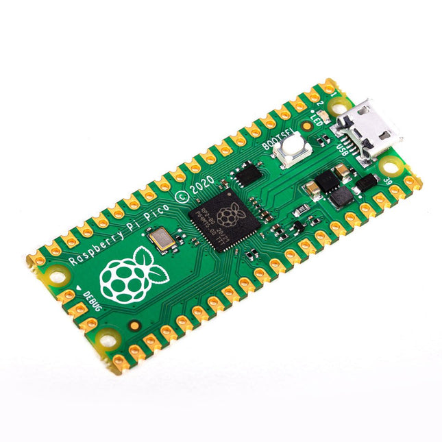
Raspberry Pi Foundation Raspberry Pi Pico
Specifications RP2040 microcontroller chip designed by Raspberry Pi in the UK Dual-core ARM Cortex M0+ processor, with a flexible clock running up to 133 MHz 264 kB SRAM, and 2 MB on-board Flash memory Castellated module allows soldering directly to carrier boards USB 1.1 host and device support Energy-efficient sleep and dormant modes Drag and drop programming using mass storage via USB 26x multifunction GPIO pins 2x SPI, 2x I²C, 2x UART, 3x 12-bit ADC, 16x controllable PWM channels On-chip accurate clock and timer Temperature sensor On-chip accelerated floating point libraries 8x programmable IO (PIO) state machines for custom peripherals Why a Raspberry Pi Pico? Designing your own microcontroller instead of buying an existing one brings a number of advantages. According to Raspberry Pi itself, not one of the existing products available for this comes close to their price/performance ratio. This Raspberry Pi Pico has also given Raspberry Pi the ability to add some innovative and powerful features of their own. These features are not available anywhere else. A third reason is that the Raspberry Pi Pico has given Raspberry Pi the ability to create powerful software around the product. Surrounding this software stack is an extensive documentation set. The software and documentation meet the high standard of Raspberry Pi's core products (such as the Raspberry Pi 400, Pi 4 Model B and Pi 3 Model A+). Who is this microcontroller for? The Raspberry Pi Pico is suitable for both advanced and novice users. From controlling a display to controlling many different devices that you use every day. Automating everyday operations is made possible by this technology. Beginner users The Raspberry Pi Pico is programmable in the C and MicroPython languages and is customizable for a wide range of devices. In addition, the Pico is as easy to use as dragging and dropping files. This makes this microcontroller ideally suited for the novice user. Advanced users For advanced users, it is possible to take advantage of the Pico's extensive peripherals. The peripherals include the SPI, I²C, and eight programmable I/O (PIO)-state machines. What makes the Raspberry Pi Pico unique? What's unique about the Pico is that it was developed by Raspberry Pi itself. The RP2040 features a dual-core Arm Cortex-M0+ processor with 264 KB of internal RAM and support for up to 16 MB of off-chip Flash. The Raspberry Pi Pico is unique for several reasons: The product has the highest price/quality ratio in the microcontroller board market. The Raspberry Pi Pico has been developed by Raspberry Pi itself. The software stack surrounding this product is of high quality and comes paired with a comprehensive documentation set.
-

Pinecone Pinecone BL602 Evaluation Board
Features Build in USB to Serial interface Build-in PCB antenna Powered by Pineseed BL602 SoC using Pinenut model: 12S stamp 2 MB Flash USB-C connection Suitable to breadboard BIY project On board three color LEDs output Dimensions: 25.4 x 44.0 mm Note: USB cable is not included.
€ 8,95€ 3,50
Best Price
-

NXP Semiconductors NXP FRDM-MCXN947 Development Board
The FRDM-MCXN947 is a compact and versatile development board designed for rapid prototyping with MCX N94 and N54 microcontrollers. It features industry-standard headers for easy access to the MCU's I/Os, integrated open-standard serial interfaces, external flash memory, and an onboard MCU-Link debugger. Specifications Microcontroller MCX-N947 Dual Arm Cortex-M33 cores @ 150 MHz each with optimized performance efficiency, up to 2 MB dual-bank flash with optional full ECC RAM, External flash Accelerators: Neural Processing Unit, PowerQuad, Smart DMA, etc. Memory Expansion *DNP Micro SD card socket Connectivity Ethernet Phy and connector HS USB-C connectors SPI/I²C/UART connector (PMOD/mikroBUS, DNP) WiFi connector (PMOD/mikroBUS, DNP) CAN-FD transceiver Debug On-board MCU-Link debugger with CMSIS-DAP JTAG/SWD connector Sensor P3T1755 I³C/I²C Temp Sensor, Touch Pad Expansion Options Arduino Header (with FRDM expansion rows) FRDM Header FlexIO/LCD Header SmartDMA/Camera Header Pmod *DNP mikroBUS User Interface RGB user LED, plus Reset, ISP, Wakeup buttons Included 1x FRDM-MCXN947 Development Board 1x USB-C Cable 1x Quick Start Guide Downloads Datasheet Block diagram


