Modules
-
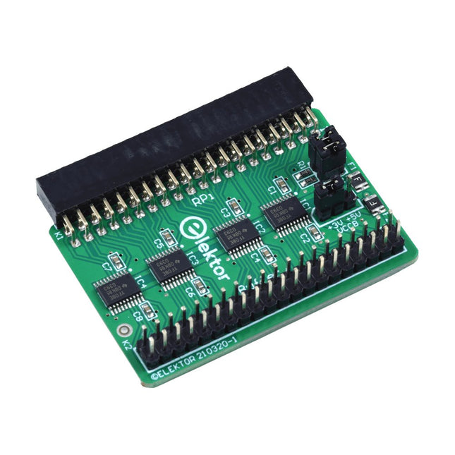
Elektor Labs Elektor Raspberry Pi Buffer Board
When you experiment with the Raspberry Pi on a regular basis and you connect a variety of external hardware to the GPIO port via the header you may well have caused some damage in the past. The Elektor Raspberry Pi Buffer Board is there to prevent this! The board is compatible with Raspberry Pi Zero, Zero 2 (W), 3, 4, 5, 400 and 500. All 26 GPIOs are buffered with bi-directional voltage translators to protect the Raspberry Pi when experimenting with new circuits. The PCB is intended to be inserted in the back of Raspberry Pi 400/500. The connector to connect to the Raspberry Pi is a right angled 40-way receptacle (2x20). The PCB is only a fraction wider. A 40-way flat cable with appropriate 2x20 headers can be connected to the buffer output header to experiment for instance with a circuit on a breadboard or PCB. The circuit uses 4x TXS0108E ICs by Texas Instruments. The PCB can also be put upright on a Raspberry Pi. Downloads Schematics Layout
€ 34,95
Members: € 31,46
-
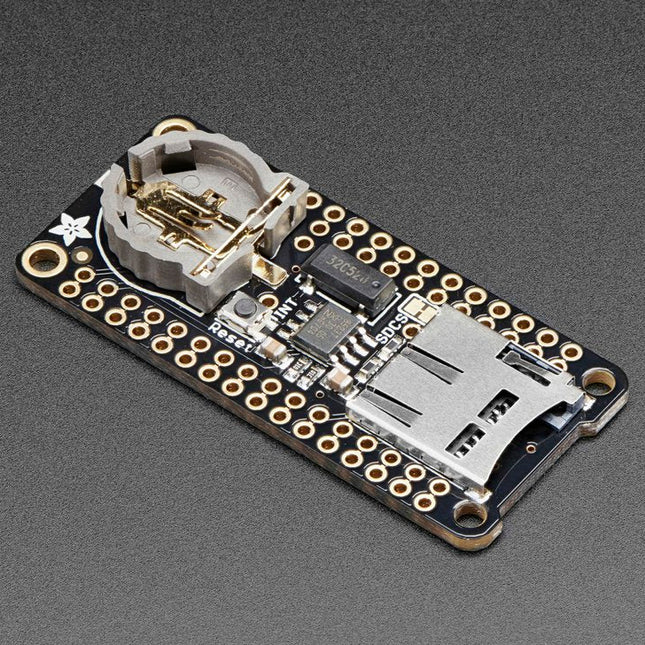
Adafruit Adafruit Adalogger FeatherWing (RTC + SD Add-on)
This FeatherWing will make it easy to add data logging to any Feather Board you might have. You get both an I²C real-time clock (PCF8523) with 32 KHz crystal and battery backup, and a microSD socket that connects to the SPI port pins (+ extra pin for CS). Note: FeatherWing doesn't come with a microSD card. A CR1220 coin cell is required to use the RTC battery-backup capabilities. If you're not using the RTC part of the FeatherWing, a battery is not required. To talk to the microSD card socket Arduino's default SD library is recommended. Some light soldering is required to attach the headers onto the Wing. Pinouts Power pins On the bottom row, the 3.3 V (second from left) and GND (fourth from left) pin are used to power the SD card and RTC (to take a load off the coin cell battery when main power is available) RTC & I²C Pins In the top right SDA (rightmost) and SCL (to the left of SDA) are used to talk to the RTC chip. SCL - I²C clock pin to connect to your microcontroller's I2C clock line. This pin has a 10 kΩ pull-up resistor to 3.3 V SDA - I²C data pin to connect to your microcontroller's I2C data line. This pin has a 10 kΩ pull-up resistor to 3.3 V There's also a breakout for INT which is the output pin from the RTC. It can be used as an interrupt output or it could also be used to generate a square wave. Note that this pin is an open drain - you must enable the internal pull-up on whatever digital pin it is connected to. SD & SPI Pins Starting from the left you've got SPI Clock (SCK) - output from feather to wing SPI Master Out Slave In (MOSI) - output from feather to wing SPI Master In Slave Out (MISO) - input from wing to feather These pins are in the same location on every Feather. They are used for communicating with the SD card. When the SD card is not inserted, these pins are completely free.

