The 8x10' iFixit Magnetic Project Mat catches and securely holds screws as you pull them out of a device. Now you can stop worrying about keeping track of all the loose screws and focus on your repair. Screws and small parts will remain right where you left them. For laptops with hundreds of screws, use the whole mat as a screw guide and keep careful location notes. Included is a pen — made by Staedtler, producer of top-of-the-line pens and pencils for artists and architects — that was specially designed for the Project Mat. The Lumocolor Correctable pen resists smears and won't wipe away with a casual brush of your hand. When your repair is complete, use the eraser tip or a dry cloth to wipe the ink away clean. Features Organize all your small parts while you work on a device. The dry-erase surface lets you keep notes and location sketches. Reduces reassembly time by up to 40% while preventing errors.
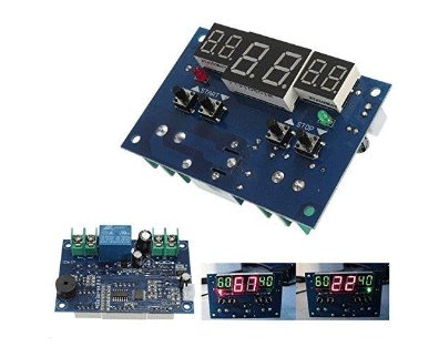
The Intelligent Digital Thermostat Temperature Controller is a small switch controller (77x51mm) which allows you to create your own thermostat. With its NTC Sensor and its LED displays, you are able to switch up to 10A 220V depending on the measured temperature.
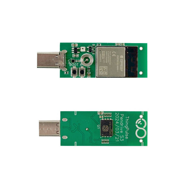
The ThingPulse Pendrive S3 is an ESP32-S3 device with USB-C plug, WS2812B RGB LED and 128 MB of flash. With the help of TinyUSB the ESP32-S3 can pretend to be many USB devices, such as:
USB Memory Stick
USB Keyboard
USB Mouse
Audio device
Video device
Networking device
Applications
As BadUSB Device with SuperWiFiDuck it can do KeyStroke injections
As WiFiDisk it can be mounted by any regular computer like a memory stick and synchronize the files on the disk to the cloud
As WiFiDongle it can add an additional WiFi networking device to any computer/phone
Included
ESP32-S3 PCB with
WS2812B RGB Led
Capacitive Touch Button (Spring)
USB Drive Plastic Enclosure
Downloads
CircuitPython
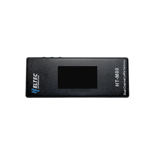
The HT-M00 is a dual-channel gateway that is specifically designed to cater to smart family LoRa applications that work with less than 30 LoRa nodes. The gateway has been built around two SX1276 chips that are driven by ESP32. To enable monitoring of 125 KHz SF7~SF12 spreading factor, a software mixer has been developed, which is commonly referred to as a baseband simulation program.
The software mixer is a critical component that enables the HT-M00 gateway to operate with high efficiency. It is designed to simulate baseband signals, which are then mixed with the radio frequency signals to produce the desired output. The software mixer has been developed with great care and precision, and has undergone rigorous testing to ensure that it is capable of delivering accurate and reliable results.
Features
ESP32 + SX1276
Emulates LoRa demodulators
Automatic adaptive spread spectrum factor, SF7 to SF12 for each channel is optional
Maximum output: 18 ±1dBm
Support for LoRaWAN Class A, Class C protocol
Specifications
MCU
ESP32-D0WDQ6
LoRa Chipset
SX1276
LoRa Band
863~870 MHz
Power Supply Voltage
5 V
Receiving Sensitivity
-110 dBm @ 300 bps
Interface
USB-C
Max. TX Power
17dB ±1dB
Operating Temperature
−20~70°C
Dimensions
30 x 76 x 14 mm
Included
1x HT-M00 Dual Channel LoRa Gateway
1x Wall bracket
1x USB-C cable
Downloads
Manual
Software
Documentation
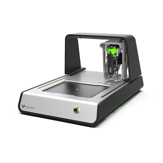
Solder Paste Dispensing and Reflow All-in-One
The Voltera V-One creates two-layer prototype circuit boards on your desk. Gerber files go in, printed circuit boards come out. The dispenser lays down a silver-based conductive ink to print your circuit right before your eyes. Assembling traditional and additive boards is easy with the V-One’s solder paste dispensing and reflow features. Simply mount your board on the print bed and import your Gerber file into Voltera’s software.
No more stencils required
Voltera’s software is designed to be understood easily. From importing your Gerber files to the moment you press print, the software safely walks you through each step.
Compatible with EAGLE, Altium, KiCad, Mentor Graphics, Cadence, DipTrace, Upverter.
Included
V-One PCB printer
V-One dispenser
V-One probe
Nozzle pack
Tip caps
3 x 4" FR1 substrate pack
2 x 3" FR1 substrate pack
Substrate clamps
Thumbscrew pack
Hello World kit
Solder wire
Tweezers
Power supply
Power adapter
Cables
User guides
Downloads
Specifications
V-One Software
Manuals
Safety Datasheets
Technical Datasheets
Voltera CAM file for EAGLE
Substrates and Templates
More Info
Frequently Asked Questions
More from the Voltera community
Technical Specifications
Printing Specifications
Minimum trace width
0.2 mm
Minimum passive size
1005
Minimum pin-to-pin pitch (conductive ink)
0.8 mml
Minimum pin-to-pin pitch (solder paste)
0.5 mml
Resistivity
12 mΩ/sq @ 70 um height
Substrate material
FR4
Maximum board thickness
3 mm
Soldering Specifications
Solder paste alloy
Sn42/Bi57.6/Ag0.4
Solder wire alloy
SnBiAg1
Soldering iron temperature
180-210°C
Print Bed
Print area
135 x 113.5 mm
Max. heated bed temperature
240°C
Heated bed ramp rate
~2°C/s
Footprint
Dimensions
390 x 257 x 207 mm (L x W x H)
Weight
7 kg
Computing Requirements
Compatible operating systems
Windows 7 or higher, MacOS 10.11 or higher
Compatible file format
Gerber
Connection type
Wired USB
Certification
EN 61326-1:2013
EMC requirements
IEC 61010-1
Safety requirements
CE Marking
Affixed to the Voltera V-One printers delivered to European customers
Designed and assembled in Canada.
More technical information
Quickstart
Explore Flexible Printed Electronics on the V-One
Voltera V-One Capabilities Reel
Voltera V-One PCB Printer Walkthrough
Unpacking the V-One
V-One: Solder Paste Dispensing and Reflow All-in-One
Voltera @ Stanford University's Bao Research Group: Robotic Skin and Stretchable Sensors
Voltera @ Princeton: The Future of Aerospace Innovation
Temporary Delay in the Delivery of Unitree Robots
Like many other suppliers, we are currently experiencing delays in the delivery of Unitree robots. A shipment from our supplier is currently held in customs, which has unfortunately led to later-than-planned deliveries for previously placed orders. We are actively working with our supplier to resolve this issue and expect more clarity soon, but at this time, we cannot provide any guarantees.
Additionally, a new shipment is already on its way, though it will take some time to arrive. Since other suppliers are facing similar challenges, switching to a different provider is unlikely to result in a faster solution. Our top priority remains fulfilling existing orders.
If you have any questions or would like to update your order, please do not hesitate to contact our customer service team. We will keep you informed of any further developments.
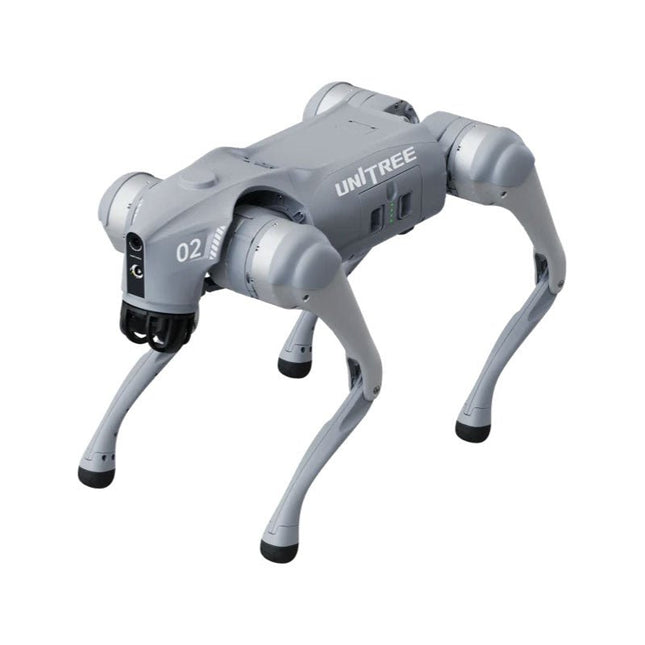
Unitree Go2 series consists of quadruped robots for the research & development of autonomous systems in the fields of human-robot interaction (HRI), SLAM & transportation. Due to the four legs, as well as the 12DOF, this robot can handle a variety of different terrains. The Go2 comes with a perfected drive & power management system, which enables a speed (depending on the version) of up to 3.7 m/s or 11.88 km/h with an operating time of up to 4 hours. Furthermore, the motors have a torque of 45 N.m at the body/thighs and at the knees, which also allow jumps or backflips.
Features
Super Recognition System: 4D LIDAR L1
Max Running Speed: approx. 5 m/s
Peak Joint Torque: approx. 45 N.m
Wireless Module: WiFi 6/Bluetooth/4G
Ultra-long battery Endurance: approx. 2-4 h (long battery life measured in real life)
Intelligent Side-follow System: ISS 2.0
Specifications
Tracking module: Remote-controlled or automatic tracking
Front camera: Image tansmission Resolution 1280x720, FOV 120°, Ultra wide angle lens deliver rich clarity
Front lamp: Brightly lights the way ahead
4D LiDAR L1: 360°x90° omnidirectional ultra-wide-angle scanning allows automatic avoidance with small blind spot and stable operation
12 knee joint motors: Strong and powerful, Beautiful and simple, Brandy new visual experience
Intercom microphone: Effective communication with no scenario restrictions
Self-retracting strap: Easy to carry and load things
More stable, more powerful with advanced devices: 3D LiDAR, 4G ESIM Card, WiFi 6 with Dual-band, Bluetooth 5.2 for stable connection and remote control
Powerful Computing Core: Motion controller, High-performance ARM processor, Improved Al algorithm processor, External ORIN NX/NANO
Smart battery: Standard 8000 mAh battery, Long-endurance 15000 mAh battery, Protection from over-temp, overcharge and short-circuit
Speaker for music play: Listen to music as your pleasure
Unitree Go2 Variants
The Go2 impresses not only with its technical capabilities, but also with a modern and slim design that gives it a futuristic look and makes it a real eye-catcher. The Go2 Air is specially designed for demos and presentations. With its basic features, it offers a solid basis for demonstrating the movement capabilities and functionality of a four-legged robot. Important: The Go2 Air is delivered without a controller. This can be purchased optionally.
With a powerful 8-core high-performance CPU, the Pro and Edu offer impressive computing power required for complex tasks and demanding calculations. This enables faster and more efficient data processing and makes the Pro and Edu a reliable partner for your projects.
From the Edu version onwards, the Go2 is programmable and opens up endless possibilities for developing and researching your own robotics applications. The Go2 is also able to handle a step height of up to 14 cm. This makes it an ideal tool for research, education and entry into the world of robotics.
The Go2 Edu comes with a remote controller that gives you easy and intuitive control. You also get a docking station with impressive computing power of 100 TOPS, which is equipped with powerful AI algorithms and offers you technical support.
Go2 Edu is equipped with a powerful 15000 mAh battery that gives it an impressive runtime of up to 4 hours. This long operating time allows the robot to carry out longer exploration missions and complete demanding tasks.
Model Comparison
Air
Pro
Edu/Edu Plus
Dimensions (standing)
70 x 31 x 40 cm
70 x 31 x 40 cm
70 x 31 x 40 cm
Dimensions (crouching)
76 x 31 x 20 cm
76 x 31 x 20 cm
76 x 31 x 20 cm
Material
Aluminium alloy + High strength engineering plastic
Aluminium alloy + High strength engineering plastic
Aluminium alloy + High strength engineering plastic
Weight (with battery)
about 15 kg
about 15 kg
about 15 kg
Voltage
28~33.6 V
28~33.6 V
28~33.6 V
Peaking capacity
about 3000 W
about 3000 W
about 3000 W
Payload
≈7 kg (MAX ~ 10 kg)
≈8 kg (MAX ~ 10 kg)
≈8 kg (MAX ~ 12 kg)
Speed
0~2.5 m/s
0~3.5 m/s
0~3.7 m/s (MAX ~ 5 m/s)
Max Climb Drop Height
about 15 cm
about 16 cm
about 16 cm
Max Climb Angle
30°
40°
40°
Basic Computing Power
N/A
8-core High-performance CPU
8-core High-performance CPU
Aluminum knee joint motor
12 set
12 set
12 set
Intra-joint circuit (knee)
✓
✓
✓
Joint Heat Pipe Cooler
✓
✓
✓
Range of Motion
Body: −48~48°
Body: −48~48°
Body: −48~48°
Thigh: −200°~90°
Thigh: −200°~90°
Thigh: −200°~90°
Shank: −156°~−48°
Shank: −156°~−48°
Shank: −156°~−48°
Max Torque
N/A
about 45 N.m
about 45 N.m
Super-wide-angle 3D LiDAR
✓
✓
✓
Wireless Vector Positioning Tracking Module
N/A
✓
✓
HD Wide-angle Camera
✓
✓
✓
Foot-end force sensor
N/A
N/A
✓
Basic Action
✓
✓
✓
Auto-scaling strap
N/A
✓
N/A
Upgraded Intelligent OTA
✓
✓
✓
RTT 2.0 Image Transmission
✓
✓
✓
App Basic Remote Control
✓
✓
✓
App Data Viewing
✓
✓
✓
App Graphical Programme
✓
✓
✓
Front Lamp (3 W)
✓
✓
✓
WiFi 6 with Dual-band
✓
✓
✓
Bluetooth 5.2/4.2/2.1
✓
✓
✓
4G Module
N/A
CN/GB
CN/GB
Voice Function
N/A
✓
✓
Music Playback
N/A
✓
✓
ISS 2.0 Intelligent side-follow system
N/A
✓
✓
Intelligent detection and avoidance
✓
✓
✓
Secondary development
N/A
N/A
✓
Manual controller
Optional
Optional
✓
High computing power module
N/A
N/A
Edu: 40 TOPS computing power
Edu Plus: 100 TOPS computing power
NVIDIA Jetson Orin (optional)
Smart Battery
Standard (8000 mAh)
Standard (8000 mAh)
Long endurance (15000 mAh)
Battery Life
1-2 h
1-2 h
2-4 h
Charger
Standard (33.6 V, 3.5 A)
Standard (33.6 V, 3.5 A)
Fast charge (33.6 V, 9 A)
Included
1x Unitree Go2 Pro
1x Unitree Go2 Battery (8000 mAh)
Downloads
Documentation
iOS/Android apps
GitHub
Specifications Operating Voltage: 3.3 V ESP-12E MCU Display Size: 1.28 inch USB Port for Power & Data Transmission Interface Pins: 4 GPIO, 1 GND, 1 Power Driver: GC9A01 Resolution240 x 240 Pixel Color: 65 K RGB Interface: SPI Downloads STEP File Dimensions 3D File Schematic GitHub
Want to make a UV detector to know the UV index when you are under the sun? Grove Sunlight Sensor is a multi-channel digital light sensor, which has the ability to detect UV-light, visible light and infrared light. This device is based on SI1151, a new sensor from SiLabs. The Si1151 is a low-power, reflectance-based, infrared proximity, UV index and ambient light sensor with I²C digital interface and programmable-event interrupt output. This device offers excellent performance under a wide dynamic range and a variety of light sources including direct sunlight. Grove Sunlight Sensor includes an on-board Grove connector, which helps you to connect it to your Arduino easily. You can use this device for making some projects which need to detect the light, such as a simple UV detector for your Raspberry Pi weather station, or a smart irrigation system using Arduino if you need to monitor the visible spectrum. Features Multi-channel digital light sensor: can detect UV-light, visible light and infrared light Wide spectrum detection range: 280-950 nm Easy to use: I²C Interface (7-bit), compatible with Grove port, just plug-and-play Programmable configuration: Versatile for various applications 3.3/5 V Supply, suitable for many microcontrollers and SBCs Applications Light detection
Smart irrigation system DIY weather station Included 1x Grove Sunlight Sensor 1x Grove Cable Downloads Schematic in PDF Schematic in Eagle File Si1145 Datasheet GitHub Repositoriy for Grove Sunlight Sensor Spectrum Lumen (unit) Ultraviolet index
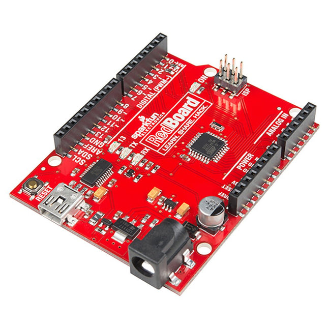
Are you tired of all the different Arduino boards, and having to choose which features you need? Wouldn't it be much simpler to have all the best features on the same board and not have to compromise? That is precisely what the people at SparkFun thought and delivered the fantastic SparkFun RedBoard Programmed with Arduino. Features ATmega328 microcontroller with Optiboot (UNO) Bootloader Input voltage: 7-15 V 0-5 V outputs with 3.3 V compatible inputs 6 Analog Inputs 14 Digital I/O Pins (6 PWM outputs) ISP Header 16 MHz Clock Spee 32 k Flash Memory R3 Shield Compatible All SMD Construction USB Programming Facilitated by the Ubiquitous FTDI FT231X Red PCB The SparkFun RedBoard combines the stability of the FTDI, the simplicity of the Uno's Optiboot bootloader, and the R3 shield compatibility of the Uno R3. RedBoard has the hardware peripherals you are used to: 6 Analog Inputs 14 Digital I/O pins (6 PWM pins) SPI UART External interrupts Downloads Drivers GitHub
Features Pitch spacing is 2.54 mm (1 to 36 contacts per row) with vertical orientation Number of contacts: 40 Number of rows: 2 Gender: receptacle Contact termination type: Through hole Contact Plating: Tin plated contacts High operating temperature range of -55°C to 105°C for matte tin plated contacts Contact material is phosphor bronze Black glass filled polyester insulator material Tiger Buy contact system Complies with UL E111594 and CSA 090871_0_000 standards
Dive into the world of Raspberry Pi with this huge book of tutorials, project showcases, guides, product reviews, and much more from the writers of The MagPi, the official Raspberry Pi magazine.
Raspberry Pi Pico 2 joins Raspberry Pi 5 in this, The Official Raspberry Pi Handbook 2025. Pico 2 comes with a faster processor than the original Pico, and uses less power – while still maintaining the same form factor and pinout. With both Pico 2 and Raspberry Pi 5 you can power any project you can imagine.
With 200 pages packed full of maker goodness, you’ll also find inspiration for your Raspberry Pi Zero 2 W, Raspberry Pi 4, or any other Raspberry Pi model you have – there’s something for everyone.
In this handbook you’ll find:
A get started guide that covers every Raspberry Pi
Everything you need to know about the brand-new Raspberry Pi Pico 2
Inspiring projects to spark your next build idea
Tutorials for makers of all skill levels
Guides for media centres, game emulators, and more!
Raspberry Pi Pico 2 Microcontroller not included
This bumper book is your definitive guide to everything Raspberry Pi. It’s essential for any maker with big dreams and a thirst for knowledge.
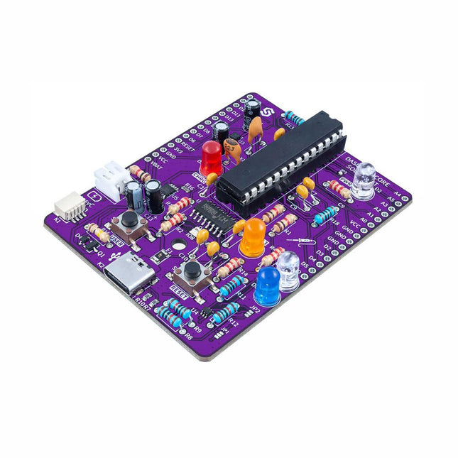
If you’re looking for a simple way to start soldering or just want to make your own Dasduino, this soldering set is a great opportunity. "Make your own Dasduino CORE" is an educational set for learning the skill of soldering, with which you end up with a functional microcontroller board. As with the other SMD versions of the Dasduino CORE boards we offer, the possibilities are endless.
It is based on the ATmega328P microcontroller, and all SMD components are already soldered on the board. The set also includes a THT socket for the microcontroller, which simplifies the replacement of the microcontroller should it ever become necessary.
Included
1x PCB
7x Capacitors (100nF)
4x Capacitors (2.2uF)
2x Capacitors (22pF)
5x Resistors (2.2 kOhm)
5x Resistors (10 kOhm)
3x Resistors (1 kOhm)
1x Resistor (100 kOhm)
1x Resistor (100 ohm)
1x JST battery connector
1x LED (purple)
1x LED (white)
1x LED (blue)
1x LED (red)
1x LED (orange)
1x Socket for ATmega328P
1x ATmega328P microcontroller
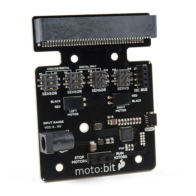
Onboard each moto:bit are multiple I/O pins, as well as a vertical Qwiic connector, capable of hooking up servos, sensors and other circuits. At the flip of the switch, you can get your micro:bit moving! The moto:bit connects to the micro:bit via an updated SMD, edge connector at the top of the board, making setup easy. This creates a handy way to swap out micro:bits for programming while still providing reliable connections to all of the different pins on the micro:bit. We have also included a basic barrel jack on the moto:bit that is capable of providing power to anything you connect to the carrier board. Features More reliable Edge connector for easy use with the micro:bit Full H-Bridge for control of two motors Control servo motors Vertical Qwiic Connector I²C port for extending functionality Power and battery management onboard for the micro:bit
Inventor 2040 W is a multi-talented board that does (almost) everything you might want a robot, prop or other mechanical thing to do. Drive a couple of fancy motors with encoders attached? Yep! Add up to six servos? Sure? Attach a little speaker so you can make noise? No problem! It's also got a battery connector so you can power your inventions from AA/AAA or LiPo batteries and carry your miniature automaton/animated top hat/treasure chest that growls at your enemies around with you untethered.
You also get a ton of options for hooking up sensors and other gubbins – there's two Qw/ST connectors (and an unpopulated Breakout Garden slot) for attaching breakouts, three ADC pins for analog sensors, photoresistors and such, and three spare digital GPIO you could use for LEDs, buttons or digital sensors. Speaking of LEDs, the board features 12 addressable LEDs (AKA Neopixels) – one for each servo and GPIO/ADC channel.
Features
Raspberry Pi Pico W Aboard
Dual Arm Cortex M0+ running at up to 133 Mhz with 264 kB of SRAM
2 MB of QSPI flash supporting XiP
Powered and programmable by USB micro-B
2.4 GHz wireless
2 JST-SH connectors (6 pin) for attaching motors
Dual H-Bridge motor driver (DRV8833)
Per motor current limiting (425 mA)
Per motor direction indicator LEDs
2 pin (Picoblade-compatible) connector for attaching speaker
JST-PH (2 pin) connector for attaching battery (input voltage 2.5-5.5 V)
6 sets of header pins for connecting 3 pin hobby servos
6 sets of header pins for GPIO (3 of which are ADC capable)
12x addressable RGB LEDs/Neopixels
User button
Reset button
2x Qw/ST connectors for attaching breakouts
Unpopulated headers for adding a Breakout Garden slot
Fully assembled
No soldering required (unless you want to add the Breakout Garden slot).
C/C++ and MicroPython libraries
Schematic
Downloads
Download pirate-brand MicroPython
Getting Started with Raspberry Pi Pico
Motor function reference
Servo function reference
MicroPython examples
C++ examples
The Ynvisible Segment E-Paper Displays are thin & flexible, sunlight readable, very easy to operate, and that they are the most energy-efficient display technology on the market for most applications. Get started today! Evaluate the ultra-low-power, thin and flexible Segment E-Paper Displays. The kit contains display designs and includes a manual display driver as well as a display driver with I²C interface. Display parameters White Reflectance 40% Contrast Ratio (Yb/Yd) 1:3 Angle Dependency No, lambertian Thickness 300 µm Graphical layout Segments Segment dimensions 1-100 mm Response time 100-1000 ms Power parameters Driving voltage 1.5 V Driving method Direct drive Energy consumption 1 mJ/cm^2 Pulse energy 0.25 mJ/cm^2 Image retention w/o power 1-5 minutes Operating conditions -20°C - +60°C Activations/Cycles 1.000.000 Included
Ynvisible Segment Displays (Segmented e-paper displays with different layouts, shapes, and symbols, suitable for testing and evaluation.) 3 single-digit display 1 double-digit display 5 single-segment/icon displays 4 progress bars (7-segment and 3-segment)
Manual Display Clicker (Manual display controller for ON/OFF operations)
Display Driver and Software Library (Dedicated display driver with I²C communication interface. Compatible with Arduino and other easy-to-use development boards.)
Flexible Display Adapter (For convenient connection of the flexible displays on a plastic substrate to rigid electronics (such as development boards), using a FFC/FPC connector.) Downloads Datasheet Guide & Instructions
Grove LED Bar is comprised of a 10 segment LED gauge bar and an MY9221 LED controlling chip. It can be used as a indicator for remaining battery life, voltage, water level, music volume or other values that require a gradient display. There are 10 LED bars in the LED bar graph: one red, one yellow, one light green, and the rest green. Demo code is available to get you up and running quickly. It lights up the LEDs sequentially from red to green, so the entire bar graph is lit up in the end. Want to go further? Go ahead and code your own effect! Features Each LED segment can be controlled individually via code Grove module Plug-and-play Can be cascaded for a larger display Flexible power option, supports 3-5.5 DC Available demo code Dimensions: 40 x 20 x 18 mm
Included 1x Grove LED Bar v2.0 1x Grove Cable Downloads Grove LED Bar Eagle File Grove LED Bar Library MY9221 Datasheet Suli-compatible Library GitHub repository for LED Bar 10 Segment LED Gauge Bar
Features Supports NMEA and U-Blox 6 protocols. Low power consumption Baud rates configurable Grove UART interface Specifications Dimensions 40 mm x 20 mm x 13 mm Update Rate 1 Hz, max 10 Hz Baud Rate 9,600 – 115,200 Input Voltage 3.3 V / 5 V Navigation Sensitivity -160dBm Power Requirements 3.3/5V Number of Channels 22 tracking, 66 channels Time to first start Cold start: 13s Warm start: 1-2s Hot start: < 1s Antennas Antenna included Accuracy 2.5m GPS Horizontal Position Accuracy
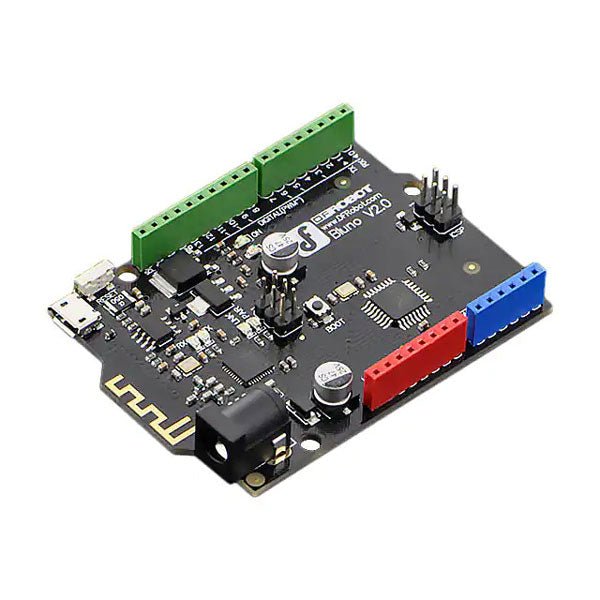
Bluno is the first of its kind in integrating Bluetooth 4.0 (BLE) module into Arduino Uno, making it an ideal prototyping platform for both software and hardware developers to go BLE. You will be able to develop your own smart bracelet, smart pedometer, and more. Through the low-power Bluetooth 4.0 technology, real-time low energy communication can be made really easy.
Bluno integrates a TI CC2540 BT 4.0 chip with the Arduino UNno. It allows wireless programming via BLE, supports Bluetooth HID, AT command to config BLE and you can upgrade BLE firmware easily. Bluno is also compatible with all 'Arduino Uno' pins which means any project made with Uno can directly go wireless!
Specifications
On-board BLE chip: TI CC2540
Wireless Programming via BLE
Support Bluetooth HID
Support AT command to config the BLE
Transparent communication through Serial
Upgrade BLE firmware easily
DC Supply: USB Powered or External 7~12 V DC
Microcontroller: Atmega328
Bootloader: Arduino Uno ( disconnect any BLE device before uploading a new sketch )
Compatible with the Arduino Uno pin mapping
Size: 60 x 53 mm(2.36 x 2.08')
Weight: 30 g
The matte-black circuit board is extra thick and has subtle white markings, including an alphanumeric grid and PIN labels. The wiring pattern – that of classic breadboards – is easy to see by looking at the exposed traces on the bottom of the board.
The kit comes complete with the 'Integrated Circuit Leg' stand and 8 colour-coded thumbscrew terminal posts. Using the terminal posts and solder points, you can hook up to your 'IC' with bare wires, lugs, alligator clips, and/or solder joints. Connections to the 8 terminal posts are through the three-position strips on the PCB; each is labelled with the corresponding PIN.
Features
Anodized aluminium stand
8-32 size press-fit threaded inserts (8 pieces) pre-installed in the protoboard
All materials (including the circuit board and stand) are RoHS compliant (lead-free)
Tri lobular thread forming screws (6 pieces, black, 6-32 thread size) and spacers for mounting the stand.
Dimensions: 13.25 x 8.06 x 2.54 mm
Dimensions assembled: 13.25 x 9.9 x 4.3 cm
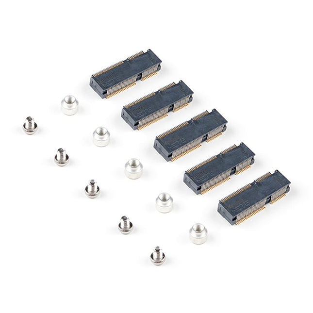
The MicroMod DIY Carrier Kit includes five M.2 connectors (4.2mm height), screws, and standoffs so that you can get all the special parts you may need to make your own carrier board. MicroMod uses the standard M.2 connector. This is the same connector found on modern motherboards and laptops. There are various locations for the plastic ‘key’ on the M.2 connector to prevent a user from inserting an incompatible device. The MicroMod standard uses the ‘E’ key and further modifies the M.2 standard by moving the mounting screw 4mm to the side. The ‘E’ key is fairly common so a user could insert an M.2 compatible Wifi module. Still, because the screw mount doesn’t align, the user would not secure an incompatible device into a MicroMod carrier board. Features 5x Machine Screws Phillips Head #0 (but #00 to #1 works) Thread: M2.5 Length: 3 mm 5x SMD Reflow Compatible Standoffs Thread: M2.5 x 0.4 Height: 2.5 mm 5x M.2 MicroMod Connectors Key: E Height: 4.2 mm Pin count: 67 Pitch: 0.5 mm
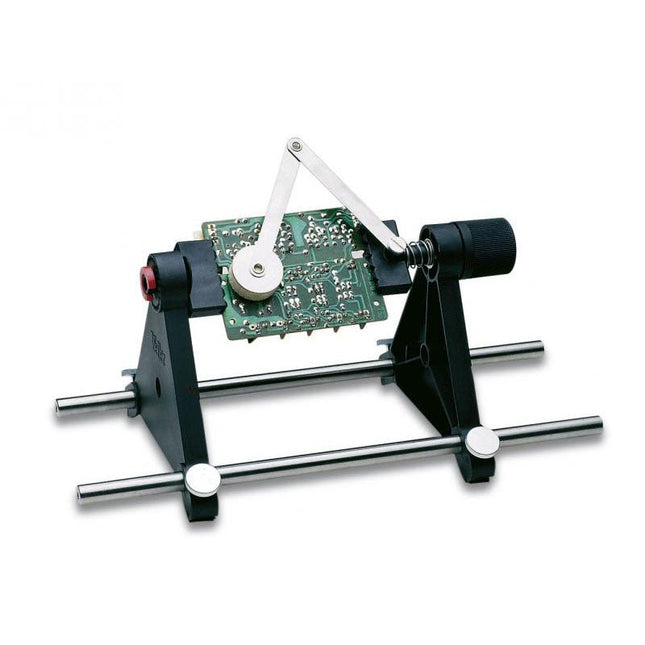
This fast mounting frame has a spring clamp, rotates through 360° in increments of 15° and has a cushioned pressure arm for keeping components in place when you flip the board upside down for soldering.
Max. size 160 x 235 mm
Rotates through 360° in increments of 15°
Spring clamp
Cushioned arm for component fixing
PCB holder
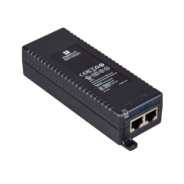
The Raspberry Pi PoE+ Injector adds Power-over-Ethernet (PoE) functionality to a single port of a non-PoE Ethernet switch, delivering both power and data through one Ethernet cable. It provides a plug-and-play, cost-effective solution for incrementally introducing PoE capability into existing Ethernet networks.
The PoE+ Injector is a single-port, 30 W device suitable for powering equipment compliant with IEEE 802.3af and 802.3at standards, including all generations of Raspberry Pi PoE HATs. It supports network pass-through speeds of 10/100/1000 Mbps.
Note: A separate IEC mains cable is required for operation (not included).
Specifications
Data rate
10/100/1000 Mbps
Input voltage
100 to 240 V AC
Output power
30 W
Power output on pins
4/5 (+), 7/8 (–)
Nominal output voltage
55 V DC
Data connectors
Shielded RJ-45, EIA 568A and 568B
Power connector
IEC c13 mains power input (not included)
Storage humidity
Maximum 95%, non-condensing
Operating altitude
–300 m to 3000 m
Operating ambient temperature
10°C to +50°C
Dimensions
159 x 51.8 x 33.5 mm
Downloads
Datasheet
This IPS 7.9-inch HDMI touch display with 400 x 1280 resolution, 170° wide viewing angle and built-in ferrite Hi-Fi speaker can be used as a secondary screen for chassis and also supports Raspberry Pi and Jetson Nano.
Features
7.9-inch IPS display with a hardware resolution of 400 x 1280.
Zinc alloy case, toughened glass panel with up to 6H hardness.
When working as a computer monitor, it supports Windows without a driver.
When working with Raspberry Pi, it supports Raspberry Pi OS / Ubuntu / Kali and Retropie, driver-free.
When working with Jetson Nano, it supports Ubuntu, driver-free.
Support backlight control for power saving.
Support 5-point capacitive touch control.
Specifications
Display size
7.9 inch
Viewing angle
170°
Resolution
400 x 1280 pixels
Display area
191.08 x 60.40 mm
IPS version solor gamut
62% NTSC
Max brightness
550 cd/m²
Backlight adjustment
Adjusted by the key/HID software
Contrast
900:1
Color depth
16.7M
Refresh rate
60 Hz
Power port
USB-C
Display port
HDMI interface
Dimensions
211 x 73 x 20 mm
Included
1x 7.9-inch Side Monitor
1x HDMI to Micro HDMI adapter
1x USB Type-A to Type-C cable (1 m)
1x HDMI flat cable (1 m)
2x Nonskid rubber feet
Downloads
Wiki
Pixel Pump is an open source vacuum pump for manual SMT assembly. It comes with a comfortable pen, a foot pedal, RGB LED buttons, and a variety of features that make hand assembly a lot more fun. It’s the perfect companion for manual SMT soldering applications, from individual prototypes to small production runs.
Thoughtful, High-Quality Design
Pixel Pump ships with a set of five stainless-steel nozzles in each of five different sizes, with outer diameters ranging from 0.3 mm all the way up to 1.8 mm. With this set, you should be able to pick and place most SMD components, including small 0402 passives, larger parts like inductors and ICs, and just about everything in between. The nozzles are held in place by a Luer lock slip fitting that facilitates quick nozzle changes and broad compatibility with third-party nozzles. The pen itself features a barbed connection for the air hose and incorporates four M8 steel nuts to give it some heft and to enable magnetic attachment to Pixel Pump.
Tactile silicone buttons with RGB backlighting offer full control over the unit. You can change operation modes, switch between high- and low-power settings, or activate reverse mode to clean your nozzle. The buttons also allow you to configure things like vacuum power and LED brightness.
Pixel Pump has a pressure-relief valve that dumps vacuum to ensure that your part gets released quickly when you release the foot pedal. Optionally, you can configure that valve to switch from suction mode to pressure mode, which quickly and easily cleans the nozzle in case you have accidentally sucked in debris like solder paste.
A sintered air filter protects the vacuum pump and valves from debris that might otherwise be sucked into the system. It is accessible from the outside and can easily be cleaned and reused.
A Perfect Companion For Prototype Boards & Small-Scale Manufacturing
Pixel Pump was designed primarily for individuals and organizations that manufacture one-off prototypes, but it’s also well suited for small production runs. It’s super easy to use and is actually faster than an automated pick-and-place machine for smaller batch sizes, especially when combined with SMD Magazines. Pixel Pump is the perfect companion for hobbyists and professionals who love making their own PCBs.
Features
Comfortable pen that accommodates various vacuum nozzles
Small, flexible, heat-resistant silicone hose that connects the pen to Pixel Pump
Magnetic base for the pen
Strong, adjustable vacuum, perfect for picking small and large components alike
Tactile, silicone RGB-button interface
Foot pedal for triggering the pump
Adjustable high/low power settings
Adjustable LED brightness
Reverse mode, which creates pressure instead of suction to clean nozzles
Vacuum relief valve for quick depressurization to drop parts more quickly
Easy software updates via USB Type-C
Compact design that respects the limited surface area of your workbench
Downloads
3D STL Files
Firmware
Mainboard Schematics
UI Board Schematics
Motor Controller Schematics