Kits
-

Elektor Zener Diode Tester
The Elektor Zener Diode Tester is essentially a constant-current source that can be switched in steps from 1 to 50 mA. It can be used to test Z-diodes up to a maximum of 54 V. Thanks to a 60-V step-up converter, the device can be powered by the usual 5 to 12 V. The principle of this tester is straightforward. A Z-diode or other DUT (device under test, such as an LED) is biased by an adjustable current source. The voltage across the DUT can be measured with a multimeter. The voltage of most (small) Z-diodes is specified at a current of 5 mA. Depending on the application, the voltage at other currents can also be of interest. That is why six current settings are available: 1, 2, 5, 10, 20, and 50 mA. LEDs are often specified at a current of 20 mA. What can be tested is: Whether a Z-diode is defective (short circuit or high impedance). Whether a Z-diode exhibits the correct Z-voltage. How a Z-voltage changes with different currents. What exact voltage is present at an integrated voltage reference. Whether LEDs in a series chain differ in brightness (hence the 20 mA current). What the current gain is for different base currents in (power) transistors. The kit contains all parts listed in the bill of materials including PCB and enclosure. Specifications Supply voltage 5…12 V/2 A (USB-C) Supply current (Itest = 50 mA) 1.1 A @ 5 V / 412 mA @ 12 V Selectable currents 1, 2, 5, 10, 20, and 50 mA Max. test voltage >54 V @ Itest ≥1 mA Max. output voltage 60 V @ Itest = 0 mA Voltage limit at 5 V 4.5 V @ Itest = 1 mA / 5.18 V @ Itest = 50 mA Enclosure dimensions 110 x 82 x 44 mm PCB size 105.4 x 67.3 mm Connections 4 mm banana sockets for multimeter 2 mm banana sockets for test clips USB-C socket for power supply Included Resistors R1 = 3.3 kΩ, 600 mW, 1% R2 = 0.15 Ω, 1 W, 5%, LS 12.7 mm, ø 3.5 mm R3, R8 = 180 Ω, 600 mW, 1% R4, R6, R16 = 1 kΩ, 600 mW, 1% R5, R19 = 47 kΩ, 600 mW, 1% R7 = 3.9 kΩ, 1 W, 5%, LS 12.7 mm, ø 3.5 mm R9, R10, R12 = 10 kΩ, 600 mW, 1% R11, R13 = 100 Ω, 600 mW 1% R14 = 249 Ω, 600 mW, 1% R15 = 499 Ω, 600 mW, 1% R17 = 2.49 kΩ, 250 mW, 1% R18 = 4.99 kΩ, 250 mW, 1% Capacitors C1 = 470 uF / 35 V, 20%, Ir = 1.86 A, ø 12.5 mm, LS 5 mm, ESR = 0.038 Ω (Panasonic EEUTP1V471) C2 = 1 uF / 100 V, 10%, X7R, LS 5 mm C3 = 2.2 nF / 50 V, 10%, X7R, LS 5 mm C4, C7 = 100 nF / 100 V, 10%, X7R, LS 5 mm C5 = 100 uF / 100 V, 20%, ø 14 mm max., LS 5 mm C6 = 1 nF / 100 V, 10%, X7R, LS 5 mm Inductor L1 = 100 uH, Irms = 2.4 A, Isat = 3.5 A, 0.09 Ω, radial, pitch 2.5/5/10 mm, ø 14 mm max. (Kemet SBC8-101-242) Semiconductors D1 = MUR120G, DO-41 D2, D4 = STPS3150RL, DO-201AD D3 = Z-diode, 18 V, 1.3 W (BZX85C18) D5 = Z-diode, 5.1 V, 0.5 W (1N5231B) LED1 = LED in pushbutton S1 LED2 = LED, green, 3 mm IC1 = MC34063, DIP-8 IC2 = LM4040BIZ-5.0/NOPB, TO-92 (TO-226AA-3) IC3 = TL051CP, DIP-8 T1 = BC327.25, TO-92 T2 = STP40NF10L, TO-220 T3 = IRF9510PBF, TO-220 T4 = 2N7000, TO-92 Others K1, K2, S1, S3 = 2-way screw terminal block, LS 3.5 mm, max. 1.5 mm² connected to K1 = USB-C socket, 30 V/3 A, chassis mounted, wired, 9 x 16 mm connected to K2 = Banana Connector, 2 mm, Socket, 60 VDC, Panel Mount, red (Multicomp 24.102.1) connected to K2 = Banana Connector, 2 mm, Socket, 60 VDC, Panel Mount, black (Multicomp 24.102.2) Test clip, red, 30 VAC/60 VDC (Hirschmann 931467101) Test clip, black, 30 VAC/60 VDC (Hirschmann 931467100) S1 = Pushbutton, panel mount, SPST-NO, 30 DC/100 mA, with red LED S2 = Rotary Switch, 6 position, 2 pole, 30°, 250 V/150 mA S3 = Toggle switch, panel mount, SPDT, solder lugs, 28 VDC T2, T3 = Heat sink, 15°C/W, FK 214 SA-CB Enclosure Hammond 1591XXSSBK, ABS, 110 x 82 x 44 mm Knob for S2, round shaft 6 mm, ø 21 mm, with indicator line (Multicomp CP-LB21-6-6D) 4 x Self-tapping screw #4-1/4", carbon steel, pan head Banana plug, red, 2 mm, 60 VDC (Multicomp 25.205.1) Banana plug, black, 2 mm, 60 VDC (Multicomp 25.205.2) Banana socket, black 4 mm, panel mount Banana socket, red 4 mm, panel mount for LED1, LED2 = Pin header, 1 x 2, vertical, pitch 2.54 mm for LED1, LED2 = Pin socket, 1 x 2, vertical, pitch 2.54 mm for T2, T3 = M3 screw, 10 mm, steel, pan head 2 x M3 washer, plain, steel 4 x M3 nut for IC1, IC3 = DIP-8 socket Wire, black, 0.25 mm² (24 AWG), stranded 14 x 0.15 mm, 1 m Wire, red, 0.25 mm² (24 AWG), stranded 14 x 0.15 mm, 1 m PCB 250772-1 v1.1 Links Elektor Labs
€ 99,95€ 84,95Best Price
-

Elektor Labs Elektor Low-Noise Lab Power Supply
The Elektor Low-Noise Lab Power Supply is a fully analogue, adjustable, medium-power symmetrical bench supply that contains no switching or digital components. It provides an output voltage adjustable between 0 V and ±22 V, and an output current adjustable from 0 A to 1 A. Because it avoids any form of switching circuitry, the design delivers extremely low noise. To display both output voltages and currents, four miniature moving-coil panel meters are used. Most modern laboratory power supplies and AC adapters employ switch-mode techniques. Even the best examples inevitably exhibit high-frequency ripple and other switching artefacts on their output, which can interfere with the testing of sensitive analogue circuits and disturb low-level measurements. To overcome this, the concept here is a completely analogue power supply. Although less efficient than its switch-mode counterparts, the reduced efficiency is of little importance for test-bench use and ensures cleaner, more reliable measurement results. Because many analogue circuits require a symmetrical supply, this design delivers positive and negative output voltages of equal magnitude. A small amount of adjustment is available to compensate for any imbalance. Naturally, a variable current-limit function is also included. The kit includes the components required to build the power supply, except for the transformers. Specifications Output Voltage 0…+22 V, 0, −22 V Output Current 0…+1 A, 0…−1 A Noise −85 dBV, (at 0.95 A/20 V, B = 22 kHz) −84 dBV (at 0.95 A/20 V, B > 500 kHz) Ripple 50 µVRMS (at 950 mA/20 V, B = 22 kHz, mainly 100 Hz component) Included 3x PCBs: Regulator (PCB-1), Mains Filter (PCB-2) and Transformer (PCB-3) All the components except the AC transformers 4x moving-coil meters Additional parts for wiring (wires, banana sockets, IEC Power entry module, etc.) Not included The three AC transformers An enclosure Parts List For the Regulator PCB (240386-1) Resistors (250 mW, 1%) R1 = 12 Ω R2, R8, R37, R62 = 1 MΩ R3, R7, R10, R13, R17, R20, R22, R30, R35, R42, R45, R47, R55, R60 = 100 Ω, 600 mW R4, R5 = 4.7 kΩ R6 = 100 kΩ R9, R12, R14, R36, R38, R39, R61, R63, R66, R72, R78, R79 = 10.0 kΩ, 600 mW R11 = 9.76 kΩ, 600 mW R15, R40 = 44.2 kΩ, 600 mW R16, R41, R77 = 1 kΩ R18, R43 = 1.5 kΩ, 1 W, 5% R19, R44 = 470 Ω, 1 W, 5% R21, R46 = 330 Ω, 600 mW R23, R24, R48, R49 = 1.0 Ω, 1 W R25, R50 = 1 kΩ, 1 W, 5% R26, R28, R51, R53 = 1.000 kΩ 0.1%, 15 ppm/C R27, R29, R52, R54 = 10.00 kΩ 0.1%, 15 ppm/C R31, R56 = 1.2 kΩ, 1 W, 5% R32, R57 = 47 kΩ R33, R58 = 270 Ω R34, R59 = 27 kΩ R64, R69 = 12.0 kΩ R65 = 3.0 kΩ, 600 mW R67, R80 = 470 Ω, 600 mW R68, R70 = 6.8 kΩ, 600 mW R71 = 30.0 kΩ,, 600 mW R73, R74, R75, R76 = 10 MΩ P1, P2, P3 = 10 kΩ, 200 mW, 20%, potentiometer, 1 turns, single, lin., panel mount P4, P5 = 500 Ω, 500 mW, 10%, trimmer, 25 turns, 3296Y-1-501LF Bourns P6, P7 = 10 kΩ, 500 mW, 10%, trimmer, 25 turns, 3296Y-1-501LF Bourns Capacitors C1 = 100 nF, 50 V, 10%, ceramic X7R, LS 5 mm C2, C3, C6, C7, C30 = 10 µF, 63V, 20%, LS 2.5 mm, 3000hours@105°C C4, C5, C8, C9, C13, C14, C18, C19, C23, C24, C28, C29, C31, C32, C38, C39 = 100 nF, 250 V, 10%, PET, LS 7.5 mm C10, C20 = 47 nF, 100 V, 5%, PET, LS 5 mm C11, C21 = 10 nF, 100 V, 5%, PET, LS 5 mm C12, C22 = 220 µF, 35 V, 20%, 0.024 Ω, LS2.5/3.5 mm, Ir 3.4 A, 2000hours@125°C, polymer C15, C25 = 120 µF, 50 V, 20%, ESR 0.02 Ω, Diam. 10 mm max., LS 5 mm C16, C26 = 15 nF, 100 V, 5%, PET, LS 5 mm C17, C27 = 47 nF, 100 V, 5%, PET, LS 5 mm C33, C34 = 22 µF, 50 V, 20%, LS 2 mm, 10000 hours @ 105°C C35, C36, C44, C45 = 1 µF, 100 V, 10%, LS 5 mm, ceramic X7R C37 = 100 uF, 50 V, 20%. LS 3.5 mm C40, C41, C42, C43, C46, C47, C48, C49 = 1000 µF, 50 V, 20%, LS 5/7.5 mm, Ir 3.32 A, 10000hours@105°C, D 16 mm C50, C51, C52, C53 = 47 nF, 100 V, 10%, ceramic X7R, LS 5 mm Inductors L1, L2 = 4.7 µH, 3.2 A, 0.033 Ω, LS 5 mm, RLB0914-4R7ML Bourns L3 = Commom mode choke, 14.5 mH, 3 A, SSRH24NH-30145 Kemet Semiconductors D1, D2, D3, D4, D5, D9, D10, D11, D15 = BAT85, DO-34 D6, D7, D12, D13 = SR560, DO-201AD D8, D14, D16 = 1N4148, DO-35 D17 = Zenerdiode, 5.6 V, 0.5 W, DO-41 D18, D19 = 1N4004, DO-41 D20, D21 D22, D23 = V30100CI-M3/P, dual common cathode, TO-220 D24 = Zener diode, 30 V, 1 W, DO-41 LED1, LED2 = LED, red, T-1 (3 mm) LED3, LED4 = LED, green, T-1 (3 mm) TVS1, TVS2 = BZW50-33B, R6 T1, T2, T4 = BC337.25, TO-92 T3 = NJW0302G, TO-3P T5, T6, T8 = BC327.25, TO-92 T7 = NJW0281G, TO-3P T9 = BD139, TO-126 (SOT-32) IC1 = LM334Z, TO-92 IC2 = LM4040AIZ-5.0/NOPB, TO-92 (TO-226AA-3) IC3, IC4 = OPA2992IDR, SOIC-8 IC5, IC6 = OPA4992IDR, SOIC-14 IC7 = OPA992IDBVR, SOT-23-5 IC8 = LM339N, DIP-14 IC9 = LM317, TO-220 IC10 = LM337, TO-220 Others F1, F2 = 5×20 mm fuse, 1.6 A, fast acting HS1, HS2 = Heatsink MC33271 (for T3/T7), 2.7°C/W, PCB mount, height 63.5 mm K1, K4 = 3-way screw terminal block, LS 3.5 mm, max. 1.5 mm² K2, K3 = 3-way screw terminal block, LS 3.5 mm, max. 1 mm² M1, M3 = Moving coil meter, Range 30 V, type 91C4, 45×45 mm M2, M4 = Moving coil meter, Range 1 A, type 91C4, 45×45 mm² RE1 = Relay DPDT,5V, UA2-5NU Miscellaneous 3× 3-way screw terminal block, LS 3.5 mm, max. 1 mm² (for P1, P2, P3) 4× Pin header, 1×2, vertical, pitch 2.54 mm (for LED1, LED2, LED3, LED4) 4× Pin socket, 1×2, vertical. pitch 2.54 mm (for LED1, LED2, LED3, LED4) 2× Heatsink FK222SA220, 20°C/W, PCB mount (for IC9 & IC10) 2× Mica thermal pad for TO-220, 12×18×0.05 mm (for IC9 & IC10) 2× Insulating bushing IB 6, TO-220 (for IC9 & IC10) 2× Ceramic thermal pad, 23×20×2 mm (for T3 & T7) 2× PCB Fuse Holder, for 5×20 mm fuse, 10 A (for F1, F2) 2× Cover for PCB Fuse Holder, transparent (for F1, F2) 2× 2-way screw terminal block, LS 3.5 mm, max. 1 mm² (for M1 & M3) 2× 2-way screw terminal block, LS 3.5 mm, max. 1.5 mm² (for M2 & M4) 8× M3 solder lug, thickness 0.35 mm (for M1…M4) M4 solder lug, thickness 0.35 mm (to connect 4 mm banana connectors) Screened cable, 1 pair, 2×24 AWG/0.22 mm², 1 m (for P1, P2 & P3) IC socket, DIP, 14 contacts (for IC8) M3 washer, plain, steel M3 screw, 16 mm, steel, pan head M3 nut M3 spring washer 50 mm M3 standoff, steel, male-female 12 mm M3 standoff, steel, male-female 10 mm M3 standoff, steel, male-female M3 screw, 8 mm, steel, pan head For the Mains Fiter PCB (240386-2) Resistor R1 = 220 kΩ, 1 W, 500 V, 5% Capacitors C1, C2 = 470 nF, 305 VAC, Class X2, 11 × 27 mm max., LS 15/22.5 mm C3, C4, C5, C6 = 2.2 nF, 300 VAC, Class Y2, 13 × 4 mm, LS 10 mm, PP Inductors L1, L2 = Common-mode choke, 6.8 mH, 1.7 A, TDK B82732R2172B030 Semiconductor MOV1 = TVS varistor, 300 VAC, S14K300 (230 VAC, B72214S0301K101) and SK14K150 (150 VAC, B72214S0151K101) Others K1, K2 = 3-way screw terminal block, LS 7.62 mm F1 = Time-delay fuse, 0.5 A (230 VAC) or 1 A (115 VAC) Miscellaneous 1× Fuse holder, 5×20 mm, 10 A, 500 VAC 1× Transparent fuse cover 4× 10 mm M3 standoff, steel, male–female 4× M3 screw, 8 mm, steel, pan head 4× M3 nut For the Transformer PCB (240386-3) Resistors R1, R2 = 2.7 kΩ, 600 mW, 1% R3 = 10.0 kΩ, 600 mW, 1% Capacitor C1 = 220 µF, 50 V, 20%, Ø10 mm, LS 5 mm, 4000 h @ 105°C Transformers (not included in this kit!) TR1, TR2, TR3 = 2×7 V, 25 VA, PCB-mounted toroid, 70060K Talema Semiconductors D1–D4 = 1N4148, DO-35 D5, D6 = 1N4004, DO-41 D7 = Zener 5.6 V, 1.3 W, DO-41 LED1 = LED, red, T-1 (3 mm) IC1, IC2 = MOC8021M, CTR ≥ 1000%, DIP-6 Others F1, F2, F3 = 160 mA time-delay fuse (230 VAC) or 315 mA time-delay fuse (115 VAC) K1 = 2-way screw terminal block, LS 7.62 mm K2 = 3-way screw terminal block, LS 3.5 mm, max 1.5 mm² K3, K4 = 3-way screw terminal block, LS 3.5 mm, max 1 mm² RE1, RE2 = Relay DPDT, 5 A/250 VAC / 24 VDC Miscellaneaous 1× Pin header 1×2, pitch 2.54 mm + matching socket for LED1 3× Fuse holder 5 × 20 mm, 10 A, 500 VAC + transparent cover 3× M4 screw, 8 mm, pan head + washer for TR1-TR3 8× M3 screw, 8 mm, pan head + nut + washer 8× 10 mm M3 standoff, steel, male–female 2× IC socket, DIP-6 for IC1 & IC2 Additional Parts 1 m red insulated wire, stranded, 1.5 mm² 0.5 m blue insulated wire, stranded, 1.5 mm² 0.5 m black insulated wire, stranded, 1.5 mm², 0.5 m 2 m red insulated wire, stranded, D 0.56 mm (0.25 mm²) 2 m black insulated wire, stranded, D 0.56 mm (0.25 mm²) 0.5 m Multicore Cable, Flexible, 3 Core, 0.75 mm² (24 x 0.2 mm) Red banana socket Black banana socket Blue banana socket Green banana socket IEC Power Entry Module with switch, IEC C14 3 crimp terminals, FASTON, 4.75 x 0.81 mm 3 knobs Links Elektor Labs JumpStarter Page Article (Part 1) Article (Part 2)
€ 299,00€ 249,00Best Price
-

Elektor Labs Elektor 'Wordy' LED Christmas Tree
Multilingual DIY Kit (incl. 27 RGB LEDs + Raspberry Pi Pico) Bring some engineering magic to your festive season with the Wordy LED Christmas Tree, a unique DIY electronics kit designed by Elektor. This beautifully engineered 3D Christmas tree combines eleven PCBs, a Raspberry Pi Pico, and 27 addressable RGB LEDs to illuminate Christmas greetings in seven languages: Danish, Dutch, English, French, German, Italian, and Spanish. Unlike ordinary LED trees, each word inside the tree has its own light chamber, creating a refined, softly glowing display without sound or flicker. The LEDs are fully WS2812-compatible and driven via the popular Adafruit NeoPixel library, making custom animations and color effects easy to create. Perfect for makers, tinkerers, and festive electronics fans, this kit offers both an enjoyable build and a striking, conversation-worthy decoration. The Wordy Christmas Tree is your perfect holiday maker project! Features Multilingual greetings (7 languages) milled into the front panel 3D construction from 11 interlocking PCBs Powered by Raspberry Pi Pico 27 individually addressable RGB LEDs (pre-mounted) Smooth fade-in and fade-out animations Fully programmable using the Arduino IDE A 5-V power supply (with micro-USB connector) capable of ≥1 A is recommended for maximum brightness (not included) Dimensions (H x W x D): 130 x 115 x 75 mm Included All required PCBs with LEDs and other SMD parts mounted Raspberry Pi Pico (to be soldered & programmed by the user) 3-way pin header (to be soldered by the user) 3-way pin socket (to be soldered by the user) 4x Self-adhesive dome bumpers Project Page Elektor Labs
€ 59,95€ 49,95Best Price
-

Elektor Labs Elektor AM Transmitter Kit
Build Your Own Vintage Radio Broadcaster The Elektor AM Transmitter Kit allows streaming audio to vintage AM radio receivers. Based on a Raspberry Pi Pico microcontroller module, the AM Transmitter can transmit on 32 frequencies in the AM band, from 500 kHz up to 1.6 MHz in 32 steps of approx. 35 kHz. The frequency is selected with a potentiometer and shown on a 0.96" OLED display. A pushbutton allows toggles the transmitting mode between On and Off. The range of the transmitter depends on the antenna. The onboard antenna provides a range of a few centimeters, requiring the AM Transmitter to be placed close to or inside the radio. An external loop antenna (not included) can be connected to increase the range. The Elektor AM Transmitter Kit comes as a kit of parts that you must solder to the board yourself. Features The board is compatible with a Hammond 1593N enclosure (not included).A 5 VDC power supply with micro-USB connector (e.g., an old phone charger) is needed to power the kit (not included). Current consumption is 100 mA. The Arduino software (requiring Earle Philhower’s RP2040 Boards Package) for the Elektor AM Transmitter Kit plus more information is available at the Elektor Labs page of this project. Component List Resistors R1, R4 = 100 Ω R2, R3, R8 = 10 kΩ R5, R6, R9, R10, R11 = 1 kΩ R7 = optional (not included) P1 = potentiometer 100 kΩ, linear Capacitors C1 = 22 µF 16V C2, C4 = 10 nF C3 = 150 pF Miscellaneous K1 = 4×1 pin socket K2, K3 = 3.5 mm socket Raspberry Pi Pico pushbutton, angle mount 0.96" monochrome I²C OLED display PCB 150292-1
€ 34,95€ 29,95Best Price
-
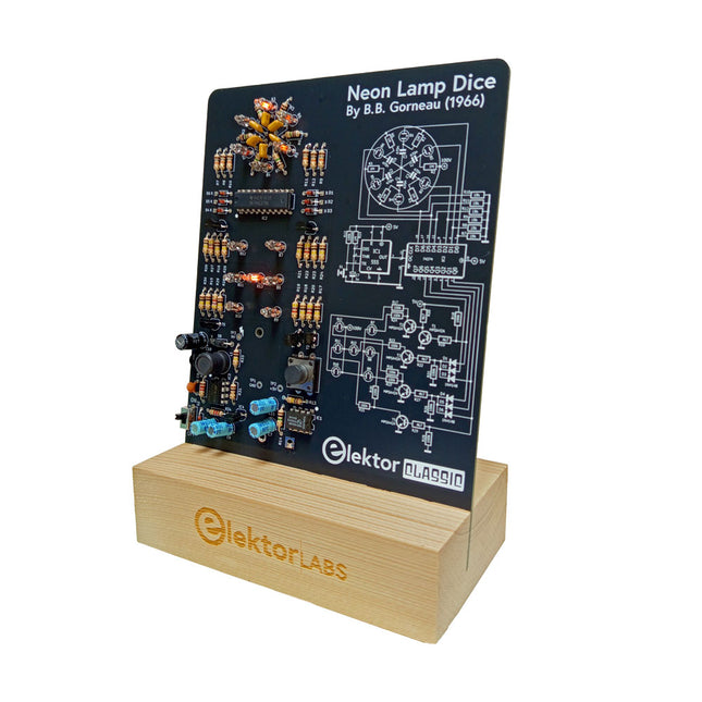
Elektor Labs Elektor Neon Lamp Dice
A Retro Roll with a Neon Soul LED-based dice are common, but their light is cold. Not so for this electronic neon dice, which displays its value with the warm glow of neon lamps. It is perfect for playing games on cold, dark winter evenings. The pips of the dice are neon lamps and the random number generator has six neon lamps to show that it is working. Even though the dice has an on-board 100-V power supply, it is completely safe. As with all Elektor Classic products, the dice too has its circuit diagram printed on the front while an explanation of how the circuit works can be found on the rear side. The Neon Lamp Dice comes as a kit of easy-to-solder through-hole parts. The power supply is a 9-V battery (not included). Features Warm Vintage Glow Elektor Heritage Circuit Symbols Tried & Tested by Elektor Labs Educational & Geeky Project Through-Hole Parts Only Included Printed Circuit Board All Components Wooden Stand Required 9 V battery Component List Resistors (THT, 150 V, 0.25 W) R1, R2, R3, R4, R5, R6, R14 = 1 MΩ R7, R8, R9, R10, R11, R12 = 18 kΩ R13, R15, R16, R17, R18, R21, R23, R24, R25, R26, R28, R30, R33 = 100 kΩ R32, R34 = 1.2 kΩ R19, R20, R22, R27, R29 = 4.7 kΩ R31 = 1 Ω Capacitors C1, C2, C3, C4, C5, C6 = 470 nF, 50 V, 5 mm pitch C7, C9, C11, C12 = 1 µF, 16 V, 2 mm pitch C8 = 470 pF, 50 V, 5 mm pitch C10 = 1 µF, 250 V, 2.5 mm pitch Inductors L1 = 470 µH Semiconductors D1, D2, D3, D4, D5, D6, D7 = 1N4148 D8 = STPS1150 IC1 = NE555 IC2 = 74HC374 IC3 = MC34063 IC4 = 78L05 T1, T2, T3, T4, T5 = MPSA42 T6 = STQ2LN60K3-AP Miscellaneous K1 = PP3 9 V battery holder NE1, NE2, NE3, NE4, NE5, NE6, NE7, NE8, NE9, NE10, NE11, NE12, NE13 = neon light S2 = Miniature slide switch S1 = Pushbutton (12 x 12 mm)
-

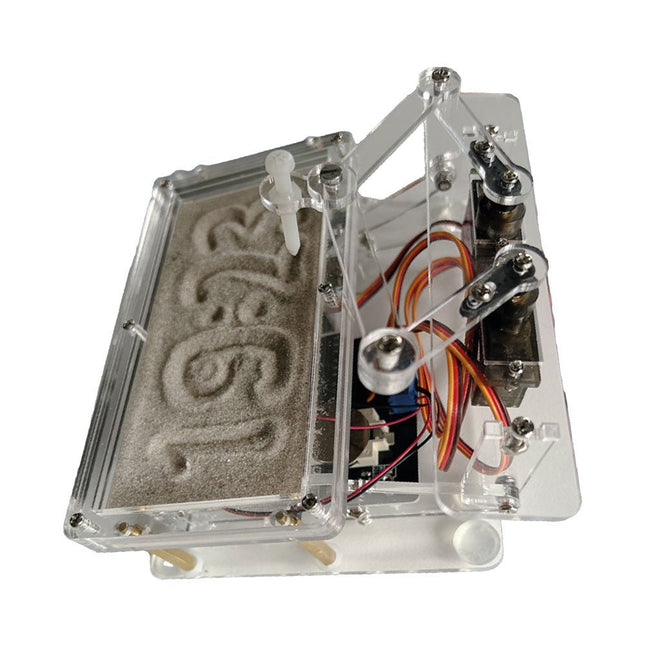
Elektor Labs Elektor Sand Clock for Raspberry Pi Pico (incl. Laser Head Upgrade)
This bundle contains the popular Elektor Sand Clock for Raspberry Pi Pico and the new Elektor Laser Head Upgrade, offering even more options for displaying the time. Not only can you "engrave" the current time in sand, you can now alternatively write it on a glow-in-the-dark foil or create green drawings. Contents of the bundle Elektor Sand Clock for Raspberry Pi Pico (normal price: €50) Elektor Laser Head Upgrade for Sand Clock (normal price: €35) Elektor Sand Clock for Raspberry Pi (Raspberry Pi-based Eye Catcher) A standard sand clock just shows how time passes. In contrast, this Raspberry Pi Pico-controlled sand clock shows the exact time by "engraving" the four digits for hour and minute into the layer of sand. After an adjustable time the sand is flattened out by two vibration motors and everything begins all over again. At the heart of the sand clock are two servo motors driving a writing pen through a pantograph mechanism. A third servo motor lifts the pen up and down. The sand container is equipped with two vibration motors to flatten the sand. The electronic part of the sand clock consists of a Raspberry Pi Pico and an RTC/driver board with a real-time clock, plus driver circuits for the servo motors. A detailed construction manual is available for downloading. Features Dimensions: 135 x 110 x 80 mm Build time: approx. 1.5 to 2 hours Included 3x Precut acrylic sheets with all mechanical parts 3x Mini servo motors 2x Vibration motors 1x Raspberry Pi Pico 1x RTC/driver board with assembled parts Nuts, bolts, spacers, and wires for the assembly Fine-grained white sand Elektor Laser Head Upgrade for Sand Clock The new Elektor Laser Head transforms the Sand Clock into a clock that writes the time on glow-in-the-dark film instead of sand. In addition to displaying the time, it can also be used to create ephemeral drawings. The 5 mW laser pointer, with a wavelength of 405 nm, produces bright green drawings on the glow-in-the-dark film. For best results, use the kit in a dimly lit room. Warning: Never look directly into the laser beam! The kit includes all the necessary components, but soldering three wires is required. Note: This kit is also compatible with the original Arduino-based Sand Clock from 2017. For more details, see Elektor Magazine 1-2/2017 and Elektor Magazine 1-2/2018.
€ 84,95€ 69,95Best Price
-
Elektor Labs Elektor Milliohmmeter Adapter
The Elektor Milliohmmeter Adapter uses the precision of a multimeter to measure very low resistance values. It is an adapter that converts a resistance into a voltage that can be measured with a standard multimeter. The Elektor Milliohmmeter Adapter can measure resistances below 1 mΩ using a 4-wire (Kelvin) method. It is useful for locating short circuits on printed circuit boards (PCB). The adapter features three measurement ranges – 1 mΩ, 10 mΩ, and 100 mΩ – selectable via a slide switch. It also includes onboard calibration resistors. The Elektor Milliohmmeter Adapter is powered by three 1.5 V AA batteries (not included). Specifications Measurement ranges 1 mΩ, 10 mΩ, 100 mΩ, 0.1% Power supply 3x 1.5 V AA batteries (not included) Dimensions 103 x 66 x 18 mm (compatible with Hammond 1593N-type enclosure, not included) Special feature On-board calibration resistors Downloads Documentation
€ 34,95
Members: € 31,46
-
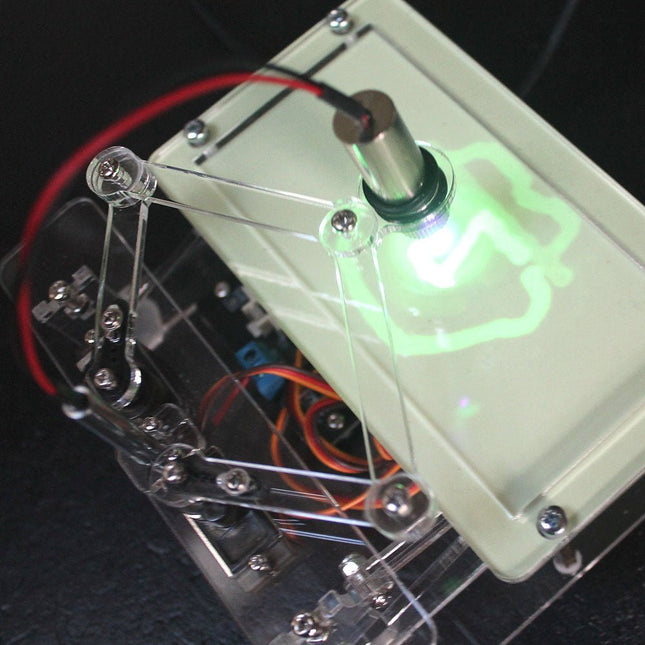
Elektor Labs Elektor Laser Head Upgrade for Sand Clock
The Elektor Laser Head transforms the Elektor Sand Clock into a clock that writes the time on glow-in-the-dark film instead of sand. In addition to displaying the time, it can also be used to create ephemeral drawings. The 5 mW laser pointer, with a wavelength of 405 nm, produces bright green drawings on the glow-in-the-dark film. For best results, use the kit in a dimly lit room. Warning: Never look directly into the laser beam! The kit includes all the necessary components, but soldering three wires is required. Note: This kit is also compatible with the original Arduino-based Sand Clock from 2017. For more details, see Elektor Magazine 1-2/2017 and Elektor Magazine 1-2/2018.
€ 34,95€ 24,95Best Price
-
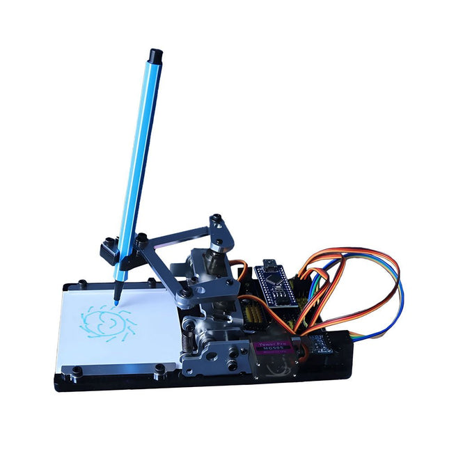
Generic Arduino-controlled Drawing Robot
This versatile plotter robot arm DIY kit for Arduino is equipped with MG90S metal gear servo motors to ensure precise and stable drawing movements. Features Fully compatible with Arduino IDE, includes complete source code for easy development and customization. Equipped with robust MG90S metal gear servo motors for accuracy and durability. Includes a Bluetooth module enabling wireless operation via a dedicated app. Specially designed robotic arm tip securely holds pens or markers with a diameter of 8-10 mm, ideal for sketches and detailed drawings. Included Arduino-compatible Nano motherboard Nano expansion board Bluetooth module MG90S all-metal gear servo motors Aluminum structural frame Thickened stable base plate Screw and fastening accessories Connecting wires USB data cable
-
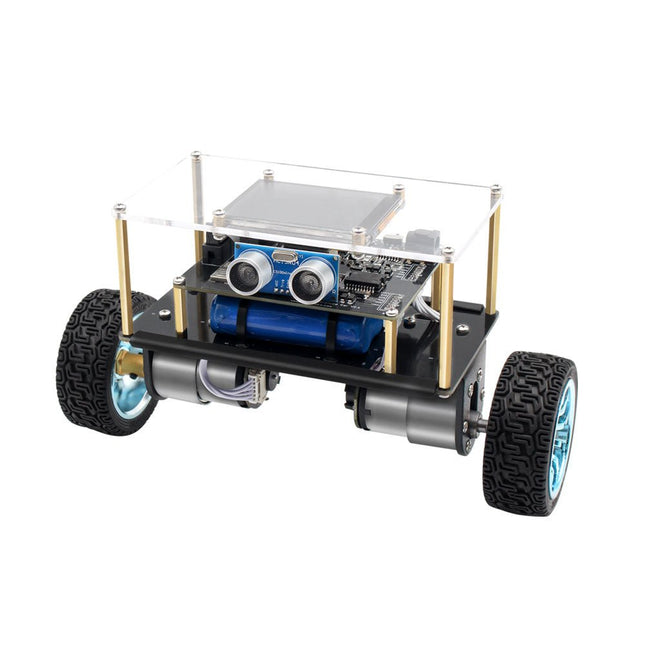
Elektor Labs Elektor Mini-Wheelie Self-Balancing Robot
Arduino-compatible, ESP32-controlled, 2-wheeled Balancing Robot The Elektor Mini-Wheelie is an experimental autonomous self-balancing robot platform. Based on an ESP32-S3 microcontroller, the self-balancing robot is fully programmable using the Arduino environment and open-source libraries. Its wireless capabilities allow it to be controlled remotely over Wi-Fi, Bluetooth or ESP-NOW or to communicate with a user or even another robot. An ultrasonic transducer is available for detecting obstacles. Its color display can be used for displaying cute facial expressions or, for the more down-to-earth users, cryptic debug messages. The robot comes as a neat kit of parts that you must assemble yourself. Everything is included, even a screwdriver. Note: The Mini-Wheelie is an educational development platform intended for learning, experimentation, and robotics development. It is not classified as a toy for children, and its features, documentation, and intended audience reflect this purpose. The product is aimed at students, educators, and developers who wish to explore robotics, programming, and hardware integration in an educational setting. Specifications ESP32-S3 microcontroller with Wi-Fi and Bluetooth MPU6050 6-axis Inertial Measurement Unit (IMU) Two independently controlled 12 V electric motors with tachometer Ultrasonic transducer 2.9" TFT color display (320 x 240) MicroSD card slot Battery power monitor 3S rechargeable Li-Po battery (11.1 V/2200 mAh) Battery charger included Arduino-based open-source software Dimensions (W x L x H): 23 x 8 x 13 cm Included 1x ESP32-S3 Mainboard + MPU6050 module 1x LCD board (2.9 inch) 1x Ultrasonic sensor 1x Battery pack (2200 mAh) 1x Battery charger 1x Motor tyre kit 1x Case board 1x Acrylic board 1x Screwdriver 1x Protective strip 1x Flex cable B (8 cm) 1x Flex cable A (12 cm) 1x Flex cable C 4x Copper column A (25 mm) 4x Copper column B (55 mm) 4x Copper column C (5 mm) 2x Plastic nylon column 8x Screws A (10 mm) 24x Screws B (M3x5) 8x Nuts 24x Metal washers 2x Zip tie 1x MicroSD card (32 GB) Downloads Documentation
-
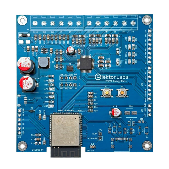
Elektor Labs Elektor ESP32 Energy Meter
The Elektor ESP32 Energy Meter is a device designed for real-time energy monitoring and smart home integration. Powered by the ESP32-S3 microcontroller, it offers robust performance with modular and scalable features. The device uses a 110/230 VAC to 12 VAC step-down transformer for voltage sampling, ensuring galvanic isolation and safety. Its compact PCB layout includes screw-type terminal blocks for secure connections, a Qwiic connector for additional sensors, and a programming header for direct ESP32-S3 configuration. The energy meter is compatible with single-phase and three-phase systems, making it adaptable for various applications. The energy meter is simple to set up and integrates with Home Assistant, offering real-time monitoring, historical analytics, and automation capabilities. It provides accurate measurements of voltage, current, and power, making it a valuable tool for energy management in homes and businesses. Features Comprehensive Energy Monitoring: Get detailed insights into your energy usage for smarter management and cost savings. Customizable Software: Tailor functionality to your needs by programming and integrating custom sensors. Smart Home Ready: Compatible with ESPHome, Home Assistant, and MQTT for full Smart Home integration. Safe & Flexible Design: Operates with a 110/230 VAC to 12 VAC step-down transformer and features a pre-assembled SMD board. Quick Start: Includes one Current Transformer (CT) sensor and access to free setup resources. Specifications Microcontroller ESP32-S3-WROOM-1-N8R2 Energy Metering IC ATM90E32AS Status Indicators 4x LEDs for power consumption indication2x Programmable LEDs for custom status notifications User Input 2x Push buttons for user control Display Output I²C OLED display for real-time power consumption visualization Input Voltage 12~16 VAC (via a step-down transformer 110/230 VAC to 12 VAC) Clamp Current Sensor YHDC SCT013-000 (100 A/50 mA) included Smart Home Integration ESPHome, Home Assistant, and MQTT for seamless connectivity Connectivity Header for programming, Qwiic for sensor expansion Applications Supports single-phase and three-phase energy monitoring systems Dimensions 79.5 x 79.5 mm Included 1x Partly assembled board (SMDs are pre-mounted) 2x Screw terminal block connectors (not mounted) 1x YHDC SCT013-000 current transformer Required Power transformer not included Downloads Datasheet (ESP32-S3-WROOM-1) Datasheet (ATM90E32AS) Datasheet (SCT013-000) Frequently Asked Questions (FAQ) From Prototype to Finished Product What started as an innovative project to create a reliable and user-friendly energy meter using the ESP32-S3 microcontroller has evolved into a robust product. Initially developed as an open-source project, the ESP32 Energy Meter aimed to provide precise energy monitoring, smart home integration and more. Through meticulous hardware and firmware development, the energy meter now stands as a compact, versatile solution for energy management.
€ 79,95€ 64,95Best Price
-
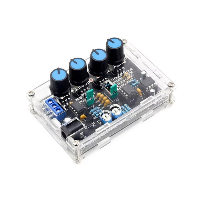
Generic ICL8038 Signal Generator DIY Kit (5 Hz – 400 kHz)
The ICL8038 signal generator delivers versatile waveforms, including sine, triangle, square, and forward/reverse sawtooth, making it suitable for a wide range of applications. Powered by the ICL8038 chip and high-speed operational amplifiers, it ensures exceptional precision and signal stability. With a frequency range of 5 Hz to 400 kHz, it supports applications from audio to radio frequencies. Its adjustable duty cycle, ranging from 2% to 95%, allows for precise waveform customization to meet various needs. The DIY kit is beginner-friendly, featuring through-hole components for easy assembly. It includes all necessary parts, an acrylic shell, and a detailed manual, providing everything required to build and use the signal generator efficiently. Specifications Frequency range 5 Hz~400 KHz (adjustable) Power supply voltage 12 V~15 V Duty cycle range 2~95% (adjustable) Low distortion sine wave 1% Low temperature drift 50 ppm/°C Output triangular wave linearity 0.1% DC bias range −7.5 V~7.5 V Output amplitude range 0.1 V~11 VPP (working voltage 12 V) Dimensions 89 x 60 x 35 mm Weight 81 g Included PCB incl. all necessary components Acrylic shell Manual
-
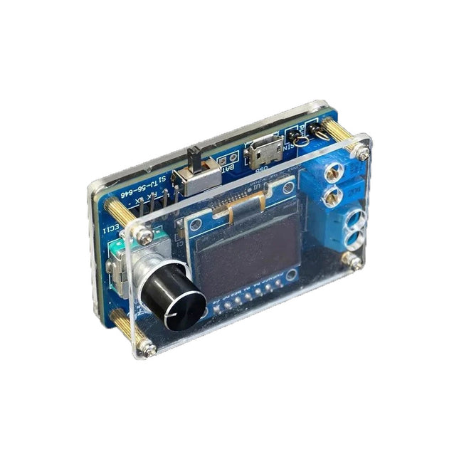
Generic DIY Mini Digital Oscilloscope Kit
The DIY Mini Digital Oscilloscope Kit (with shell) is an easy-to-build kit for a tiny digital oscilloscope. Besides the power switch, it has only one other control, a rotary encoder with a built-in pushbutton. The kit's microcontroller comes preprogrammed. The 0.96" OLED display has a resolution of 128 x 64 pixels. The oscilloscope features one channel that can measure signals up to 100 kHz. The maximum input voltage is 30 V, the minimum voltage is 0 V. The kit consists of through-hole components (THT) are surface-mount devices (SMD). Therefore, assembling the kit means soldering SMD parts, which requires some soldering experience. Specifications Vertical range: 0 to 30 V Horizontal range: 100 µs to 500 ms Trigger type: auto, normal and single Trigger edge: rising and falling Trigger level: 0 to 30 V Run/Stop mode Automatic frequency measurement Power: 5 V micro-USB 10 Hz, 5 V sinewave output 9 kHz, 0 to 4.8 V square wave output Display: 0.96-inch OLED screen Dimensions: 57 x 38 x 26 mm Downloads Documentation
-
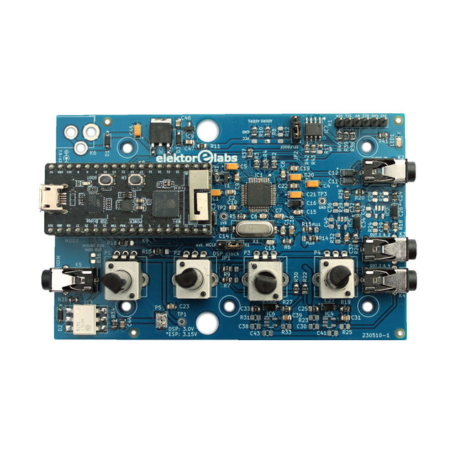
Elektor Labs Elektor Audio DSP FX Processor (New Revision)
The Elektor Audio DSP FX Processor combines an ESP32 microcontroller and an ADAU1701 Audio DSP from Analog Devices. Besides a user-programmable DSP core, the ADAU1701 has high-quality analog-to-digital and digital-to-analog converters built-in and features an I²S port. This makes it suitable as a high-quality audio interface for the ESP32. Programs for the ESP32 can be created with Arduino, Platform IO, CMake or by using the Espressif IDF in another way. Programs for the ADAU7101 audio DSPs are created with the free visual programming tool SigmaStudio by dragging and dropping pre-defined algorithm blocks on a canvas. Applications Bluetooth/Wi-Fi audio sink (e.g. loudspeaker) & source Guitar effect pedal (stomp box) Music synthesizer Sound/function generator Programmable cross-over filter for loudspeakers Advanced audio effects processor (reverb, chorus, pitch shifting, etc.) Internet-connected audio device DSP experimentation platform Wireless MIDI MIDI to CV converter and many more... Specifications ADAU1701 28-/56-bit, 50-MIPS digital audio processor supporting sampling rates of up to 192 kHz ESP32 32-bit dual-core microcontroller with Wi-Fi 802.11b/g/n and Bluetooth 4.2 BR/EDR and BLE 2x 24-bit audio inputs (2 V RMS, 20 kΩ) 4x 24-bit audio outputs (0.9 V RMS, 600 Ω) 4x Control potentiometer MIDI in- and output I²C expansion port Multi-mode operation Power supply: 5 V DC USB or 7.5-12 V DC (barrel jack, center pin is GND) Current consumption (average): 200 mA Included 1x ESP32 Audio DSP FX Processor board (assembled) 1x ESP32-PICO-KIT 2x Jumpers 2x 18-pin headers (female) 4x 10 KB potentiometers Downloads Documentation GitHub
€ 99,95€ 84,95Best Price
-

Generic LC Meter Kit
This LC meter kit is an easy-to-build, educational, and entertaining DIY project for measuring the inductance (L) of coils and inductors, the capacitance (C) of capacitors, other passive components and the frequency of signals. Specifications Power supply USB DC 5 V Capacitance measurement range of small non-polarized capacitors 1 pF~2200 pF Capacitance measurement range of electrolytic capacitors 1 µF~12000 µF Inductance measurement range 1 µH~1 H Frequency measurement range 20 Hz~400 kHz Dimensions (PCB) 91 x 80 mm Dimensions (Shell) 106 x 91 x 28 mm Included Doubled-sided PCB All required components incl. LCD display Six pre-cut transparent acrylic plates Screws and nuts
-
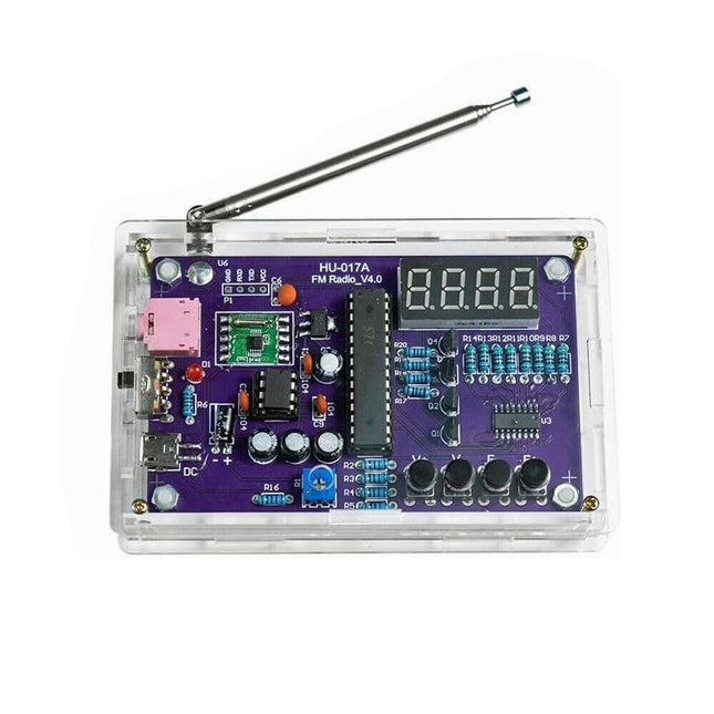
Generic FM Radio Kit
This DIY kit (HU-017A) is a wireless FM radio receiver with a 4-digit 7-segment display. It operates within the global FM receiving frequency band of 87.0-108.0 MHz, making it suitable for use in any country or region. The kit offers two power supply modes, allowing you to use it both at home and outdoors. This DIY electronic product will help you understand circuits and improve your soldering skills. Features 87.0-108.0 MHz FM Radio: Built-in RDA5807 FM data processor with a standard FM receiving frequency band. The FM frequency can be adjusted using the F+ and F- buttons. Adjustable Volume: Two volume adjustment methods – button and potentiometer. There are 15 volume levels. Active & Passive Audio Output: The kit has a built-in 0.5 W power amplifier to drive 8 Ω speakers directly. It also outputs audio signals to headsets or loudspeakers with AUX interfaces, allowing personal listening and sharing of FM audio. Configured with a 25 cm dedicated FM antenna and a (red) 4-digit 7-segment display for real-time display of FM radio frequency. The transparent acrylic shell protects the internal circuit board. It supports dual power supply methods – 5 V USB and 2x 1.5 V (AA) batteries. DIY Hand Soldering: The kit comes with various components that need to be installed manually. It helps exercise and improve soldering skills, making it suitable for electronics hobbyists, beginners, and educational purposes. Specifications Operating voltage DC 3 V/5 V Output impedance 8 Ω Output power 0.5 W Output channel Mono Receiver frequency 87.0 MHz~108.0 MHz Frequency accuracy 0.1 MHz Operating temperature −40°C to +85°C Operating humidity 5% to 95% RH Dimensions 107 x 70 x 23 mm IMPORTANT: Remove the batteries when powering the radio over to USB. Included 1x PCB 1x RDA5807M FM Receiver 1x STC15W404AS MCU 1x IC Socket 1x 74HC595D Register 1x TDA2822M Amplifier 1x IC Socket 1x AMS1117-3.3 V Voltage Converter 18x Metal Film Resistor 1x Potentiometer 4x Ceramic Capacitor 5x Electrolytic Capacitor 4x S8550 Transistor 1x Red LED 1x 4-digit 7-segment Display 1x Toggle Switch 1x SMD Micro USB Socket 1x Radio Antenna 1x AUX Audio Socket 4x Black Button 4x Button Cap 1x 0.5 W/8 Ω Speaker 1x Red/Black Wire 2x Double-sided adhesive 1x AA Battery Box 1x USB cable 6x Acrylic Board 4x Nylon Column Screw 4x M3 Screw 4x M3 Nut 4x M2x22 mm Screw 1x M2x6 mm Screw 5x M2 Nut
-

Velleman Whadda Electronic Dice
This electronic dice with 7 red LEDs rolls when the push button is released and works with a 9 V battery (not included). Downloads Manual
€ 6,50
-

Velleman Whadda 3D Xmas Tree Kit
The Whadda 3D Xmas Tree Kit is aimed at hobbyists and beginners who are interested in soldering and electronics. With this DIY kit, you can build a festive LED Christmas tree. Features 16 flashing red LEDs Extra green and yellow LEDs provided to customise your tree Can be hung on and fed through wires Will operate on 12 V DC (e.g. in cars) Specifications Low power consumption 8 mA Power supply 9 V battery operation (not included) Dimensions 102 x 88 x 80 mm Weight 65 g Downloads Manual
€ 10,95
-

Elektor Labs Elektor Arduino MultiCalculator
The Elektor MultiCalculator Kit is an Arduino-based multifunction calculator that goes beyond basic calculations. It offers 22 functions including light and temperature measurement, differential temperature analysis, and NEC IR remote control decoding. The Elektor MultiCalculator is a handy tool for use in your projects or for educational purposes. The kit features a Pro Mini module as the computing unit. The PCB is easy to assemble using through-hole components. The enclosure consists of 11 acrylic panels and mounting materials for easy assembly. Additionally, the device is equipped with a 16x2 alphanumeric LCD, 20 buttons, and temperature sensors. The Elektor MultiCalculator is programmable with the Arduino IDE through a 6-way PCB header. The available software is bilingual (English and Dutch). The calculator can be programmed with a programming adapter, and it is powered through USB-C. Modes of Operation Calculator 4-Ring Resistor Code 5-Ring Resistor Code Decimal to Hexadecimal and Character (ASCII) conversion Hexadecimal to Decimal and Character (ASCII) conversion Decimal to Binary and Character (ASCII) conversion Binary to Decimal and Hexadecimal conversion Hz, nF, capacitive reactance (XC) calculation Hz, µH, inductive reactance (XL) calculation Resistance calculation of two resistors connected in parallel Resistance calculation of two resistors connected in series Calculation of unknown parallel resistor Temperature measurement Differential temperature measurement T1&T2 and Delta (δ) Light measurement Stopwatch with lap time function Item counter NEC IR remote control decoding AWG conversion (American Wire Gauge) Rolling Dice Personalize startup message Temperature calibration Specifications Menu languages: English, Dutch Dimensions: 92 x 138 x 40 mm Build time: approx. 5 hours Included PCB and though-hole components Precut acrylic sheets with all mechanical parts Pro Mini microcontroller module (ATmega328/5 V/16 MHz) Programming adapter Waterproof temperature sensors USB-C cable Downloads Software
€ 49,95
Members: € 44,96
-
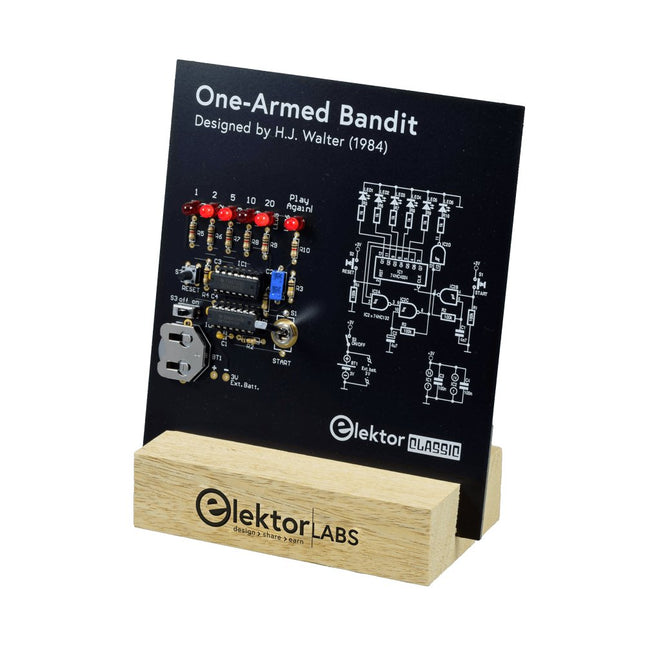
Elektor Labs Elektor One-armed Bandit
Pull Down Lever For Highest Score! This Elektor Circuit Classic from 1984 shows a playful application of CMOS 400x series logic ICs in combination with LEDs, a highly popular combination at the time. The project imitates a spinning-digit type slot machine. The Game To play the game, first agree on the number of rounds. Player 1 actuates the switch lever as long as desired and releases it. The LEDs then show the score which is the sum of the 50-20-10-5 digits lit up. If the Play Again! LED lights, Player 1 has another, “free” round. If not, it’s Player 2’s turn. The players keep tab of their scores, and the highest score wins. Features LEDs Indicate Score Multi-Player and Play Again! Elektor Heritage Circuit Symbols Tried & Tested by Elektor Labs Educational & Geeky Project Through-Hole Parts Only Included Printed Circuit Board All Components Wooden Stand Bill of Materials Resistors (5%, 250 mW) R1,R2,R3,R4 = 100kΩ R5,R6,R7,R8,R9,R10 = 1kΩ Capacitors C1 = 4.7nF, 10%, 50V, 5mm C2 = 4.7μF, 10%, 63V, axial C3,C4 = 100nF, 10 %, 50V, ceramic X7R, 5mm Semiconductors LED1-LED6 = red, 5mm (T1 3/4) IC1 = 74HC4024 IC2 = 74HC132 Miscellaneous S1 = switch, toggle, 21mm lever, SPDT, momentary S2 = switch, tactile, 24V, 50mA, 6x6mm S3 = switch, slide, SPDT IC1,IC2 = IC socket, DIP14 BT1 = PCB-mount CR2032 battery retainer clip Desktop Stand PCB 230098-1 Not included: BT1 = CR2032 coin cell battery
€ 39,95€ 15,98Best Price
-
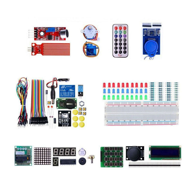
Makerfabs Arduino Uno Experimenting Kit
With this kit you can built all the projects described in the book 'Mastering the Arduino Uno R4'. The kit comes with several LEDs, sensors, actuators, and other components. The purpose of the kit is to make a flying start with hardware and software aspects of projects designed around the Arduino Uno microcontroller system. Included 1x RFID reader module 1x DS1302 clock module 1x 5 V stepper motor 1x '2003' stepper motor drive board 5x Green LED 5x Yellow LED 5x Red LED 2x Rocker switch 1x Flame sensor 1x LM35 sensor module 1x Infrared receiver 3x Light-dependent resistors (LDRs) 1x IR remote controller 1x Breadboard 4x Pushbutton (with four caps) 1x Buzzer 1x Piezo sounder 1x Adjustable resistor (potentiometer) 1x 74HC595 shift register 1x 7-segment display 1x 4-digit 7-segment display 1x 8x8 Dot-matrix display 1x 1602 / I²C LCD module 1x DHT11 Temperature and humidity module 1x Relay module 1x Sound module Set of Dupont cables Set of Breadboard cables 1x Water sensor 1x PS2 Joystick 5x 1 k-ohm resistor 5x 10 k-ohm resistor 5x 220-ohm resistor 1x 4x4 keypad module 1x 9g Servo (25 cm) 1x RFID card 1x RGB module 1x 9 V battery DC jack Not included Mastering the Arduino Uno R4 (Book) Arduino Uno R3/R4 (Board)
-
Elektor Labs Elektor Sand Clock for Raspberry Pi Pico
Raspberry Pi-based Eye Catcher A standard sand clock just shows how time passes. In contrast, this Raspberry Pi Pico-controlled sand clock shows the exact time by “engraving” the four digits for hour and minute into the layer of sand. After an adjustable time the sand is flattened out by two vibration motors and everything begins all over again. At the heart of the sand clock are two servo motors driving a writing pen through a pantograph mechanism. A third servo motor lifts the pen up and down. The sand container is equipped with two vibration motors to flatten the sand. The electronic part of the sand clock consists of a Raspberry Pi Pico and an RTC/driver board with a real-time clock, plus driver circuits for the servo motors. A detailed construction manual is available for downloading. Features Dimensions: 135 x 110 x 80 mm Build time: approx. 1.5 to 2 hours Included 3x Precut acrylic sheets with all mechanical parts 3x Mini servo motors 2x Vibration motors 1x Raspberry Pi Pico 1x RTC/driver board with assembled parts Nuts, bolts, spacers, and wires for the assembly Fine-grained white sand
€ 49,95€ 39,95Best Price
-

JOY-iT Joy-Pi Advanced Development Platform (incl. Raspberry Pi 4, 8 GB)
For a limited time, the Joy-Pi Advanced is available in a great-value bundle with a Raspberry Pi 4 (8 GB)! The Joy-Pi Advanced is a compact and powerful device that allows you to realize your projects quickly and easily. Whether you already have a lot of experience, or next to none, the Joy-Pi Advanced lets you unleash your creativity. Thanks to its compatibility with a wide range of platforms, including Raspberry Pi, Raspberry Pi Pico, Arduino Nano, BBC micro:bit, and NodeMCU ESP32, you can easily and quickly access your preferred platform. In addition, the Joy-Pi Advanced features more than 30 stations, lessons, and modules, giving you an unlimited variety of ways to get your projects done. With the self-developed learning center, you can not only improve your skills but also create new projects. The learning center offers a wealth of information and tutorials that will guide you step by step through your projects. Joy-Pi Advanced is characterized in particular by its intelligent switch units, which allow an extended use of the available pins. A total of three switch units are integrated, each equipped with 12 individual switches that provide precise control of the connected sensors and modules. This system solves the well-known problem of limited pin count that occurs with conventional microcontrollers. The switch units allow you to operate a large number of sensors and modules in parallel by switching them on and off individually. This simulates multiple pin assignment, allowing you to exploit the full power of your projects without compromising functionality. By combining innovative adapter boards and the micro:bit slot, you can achieve seamless compatibility with a wide range of microcontrollers such as Raspberry Pi Pico, NodeMCU ESP32, micro:mit and Arduino Nano. The specially developed adapter boards are designed to perfectly match the respective microcontroller. By plugging the microcontroller onto the appropriate adapter board and then plugging it into the micro:bit slot, the Joy-Pi Advanced quickly and easily becomes compatible with the different microcontrollers. This allows seamless integration of your preferred platform and the ability to combine the strengths of the different microcontrollers in your projects. This way, you can fully focus on your creative projects without worrying about the compatibility of different microcontrollers. The Joy-Pi Advanced simplifies the development process and gives you the possibility to design your projects flexibly and individually. Features Highly integrated development platform & learning center Fast, easy & wireless combination of various sensors & actuators Installation option for Raspberry Pi 4 Compatible with various microcontrollers Self-developed, didactic learning platform for Raspberry Pi & Windows Specifications Compatible to Raspberry Pi 4, Arduino Nano, NodeMCU ESP32, BBC micro:bit, Raspberry Pi Pico Installed sensors, actuators & components 39 Learning platform Over 40 entries in the know-ledge database, 10 projects, 10 learning tasks, 14 visions Displays 7-segment display, 16x2 display, 1.8“ TFT display, 0.96" OLED display, 8x8 RGB matrix Sensors DS18B20, shock sensor, hall sensor, barometer, sound sensor, gyroscope, PIR sensor, Light barrier, NTC, Light sensor, 6x touch sensor, color sensor, ultrasonic distance sensor, DHT11 temperature & humidity sensor Control Joystick, 5x switches, potentiometer, rotary encoder, 4x4 button matrix, relays, PWM fan Motors Servo interface, Stepper motor interface, Vibration motor Measuring & conversion modules Analog-Digital Converter, Level converter, voltmeter, Variable voltage supply Other components RTC real time clock, buzzer, EEPROM memory, infrared receiver, breadboard, RFID reader Adapter boards Adapter for NodeMCU ESP32, Arduino Nano & Raspberry Pi Pico, Board connectors for Raspberry Pi & External Boards Electronic components Infrared remote control, RFID chip, RFID card, 6x alligator clips, microSD card reader, servo motor, stepper motor, 32 GB microSD card Components 40x resistors, 3x green LEDs, 3x yellow LEDs, 3x red LEDs, 1x transistor, 5x buttons, 1x potentiometer, 2x capacitors Other accessories Screw assortment, screwdriver, accessory storage bag, power supply & power cable, servo mount Power supply Built-in power supply: 36 W, 12 V, 3 A Case connector: Small device plug C8 Voltage outputs 12 V, 5 V, 3.3 V, Variable voltage output (2-11 V) Data buses & signal outputs I²C, SPI, Analog to digital converter Battery (RTC) CR2032 Dimensions 327 x 200 x 52 mm Included Raspberry Pi 4 (8 GB RAM) Downloads Joy-Pi website Datasheet Manual
€ 519,00€ 419,00Best Price
-

Elektor Labs Elektor Dual DC LISN (150 kHz – 200 MHz)
Measuring conducted emission is the simplest and most affordable method of getting some indication of whether a design can meet EMI/EMC requirements. A Line Impedance Stabilization Network (LISN) is an indispensable part of an EMC pre-compliance test setup. In cooperation with Würth Elektronik, Elektor has developed a 5 µH, 50 Ω Dual DC LISN that supports voltages up to 60 V and currents up to 10 A. The instrument measures RF interferences on both channels (the power supply) by means of 5-μH blocking inductances. The internal 10-dB attenuation network – one in each channel – contains a 3rd-order high-pass filter with a cutoff frequency of 9 kHz to protect the input of instruments like a spectrum analyzer from potentially harmful DC voltages or low frequencies coming from the EUT (Equipment Under Test). Specifications RF path Channels 2 (with clamping diodes) Bandwidth 150 kHz – 200 MHz Inductance 5 μH || 50 Ω Internal attenuation 10 dB Connectors SMA DC path Max. current < 10 ADC Max. voltage < 60 VDC DC resistance < 2 x 70 mΩ PCB size 94.2 x 57.4 mm Connectors 4-mm banana Hammond enclosure Type 1590N Dimensions 121 x 66 x 40 mm Included 1x 4-layer PCB with all SMT parts fitted 1x pre-drilled enclosure with ready-printed front panel layout 5x gold-plated, insulated, 4-mm banana sockets, rated for 24 A, 1 kV 1x Hammond enclosure 1590N1, Aluminum (Die-Cast Alloy) More Info Project on Elektor Labs: Dual DC LISN for EMC pre-compliance testing Elektor 9-10/2021: EMC Pre-Compliance Test for Your DC-Powered Project (Part 1) Elektor 11-12/2021: EMC Pre-Compliance Test for Your DC-Powered Project (Part 2)


