This 5.83-inch 3-color e-paper e-ink display module for Raspberry Pi Pico offers a resolution of 648 × 480 pixels, an SPI interface, low power consumption, wide viewing angle and a paper-like effect without electricity.
Features
No backlight, keeps displaying last content for a long time even when power down
Ultra low power consumption, basically power is only required for refreshing
SPI interface, requires minimal I/O pins
2x user buttons and 1x reset button for easy interacting
Comes with development resources and manual (Raspberry Pi Pico C/C++ and MicroPython examples)
Specifications
Operating voltage
3.3 V
Display color
Red, black, white
Resolution
648 × 480 pixels
Gray scale
2
Interface
3-wire SPI, 4-wire SPI
Viewing angle
>170°
Partial refresh time
N/A
Full refresh time
5s
Outline dimensions
125.4 × 99.5 mm
Display size
119.232 × 88.320 mm
Refresh power
26.4 mW (typ.)
Standby current
<0.01 uA (almost none)
Dot pitch
0.184 × 0.184 mm
Applications
Suitable For Price Tags
Asset/Equipment Tags
Shelf Labels
Conference Name Tag
Included
1x 5.83-inch e-Paper (B)
1x Pico-ePaper-Driver-Board
1x Standoff pack
Downloads
Wiki
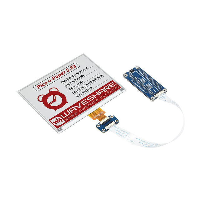
This 5.83-inch black/white e-paper e-ink display module for Raspberry Pi Pico offers a resolution of 648 × 480 pixels, an SPI interface, low power consumption, wide viewing angle and a paper-like effect without electricity.
Features
No backlight, keeps displaying last content for a long time even when power down
Ultra low power consumption, basically power is only required for refreshing
SPI interface, requires minimal I/O pins
2x user buttons and 1x reset button for easy interacting
Comes with development resources and manual (Raspberry Pi Pico C/C++ and MicroPython examples)
Specifications
Operating voltage
3.3 V
Display color
Black, white
Resolution
648 × 480 pixels
Gray scale
2
Interface
3-wire SPI, 4-wire SPI
Viewing angle
>170°
Partial refresh time
N/A
Full refresh time
5s
Outline dimensions
125.4 × 99.5 mm
Display size
119.232 × 88.320 mm
Refresh power
26.4 mW (typ.)
Standby current
<0.01 uA (almost none)
Dot pitch
0.184 × 0.184 mm
Applications
Suitable For Price Tags
Asset/Equipment Tags
Shelf Labels
Conference Name Tag
Included
1x 5.83-inch e-Paper
1x Pico-ePaper-Driver-Board
1x Standoff pack
Downloads
Wiki
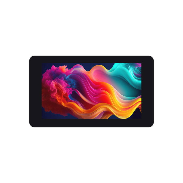
The Zero-DISP-7A is a 7″ touch display kit for Raspberry Pi Zero with IPS Display Expansion Board featuring 1024x600 pixels and 5-point capacitive touch.
Features
7-inch IPS touch display with a hardware resolution of 1024x600.
5-point touch control, toughened glass panel with up to 6H hardness.
When working with Raspberry Pi Zero, supports Raspberry Pi OS, Ubuntu, Kali, and Retropie systems.
Onboard ETH/USB HUB function, adapting RJ45 and USB port serving as an alii-in-one mini computer.
Onboard 4-pin speaker header and 3.5 mm audio jack, support for HDMI audio output.
Specifications
Zero connectors
Mini HDMI port, 2x USB Micro male port (1x HUB, 1x Power supply)
Display
7-inch 1024 x 600 pixels, 5-point capacitive touch
Networking
100M Ethernet RJ45 port
USB
2x USB 2.0 port
Audio
Headphone jack, 4-pin speaker header
Power input
USB Type-C Interface, 5V
Included
1x Zero-DISP-7A
1x Button board
1x Button board cable (9 cm)
4x White nylon spacer
Downloads
Wiki
This 7.5-inch e-paper E-Ink display HAT for Raspberry Pi with SPI interface provides low power consumption, wide viewing angle and a paper-like display of 3 colors (red, black, white) without electricity. Advantages Of E-Ink E-paper display utilizes microcapsule electrophoretic technology for displaying, the principle is: charged particles suspended in clear fluid will move to sides of microcapsule when electric field is applied, making the microcapsule become visible by reflecting ambient light, just as traditional printed paper. E-paper display will clearly display images/texts under lamplight or natural light, requires no backlight, and features nearly up to 180° viewing angle. It is usually used as e-reader due to its paper-like effect. Features No backlight, keeps displaying last content for a long time even when power down Ultra low power consumption, basically power is only required for refreshing Standard Raspberry Pi 40-pin GPIO extension header, supports Raspberry Pi series boards, Jetson Nano SPI interface, for connecting with controller boards like Raspberry Pi/Jetson Nano/Arduino/STM32, etc. Onboard voltage translator, compatible with 3.3/5 V MCUs Comes with development resources and manual (examples for Raspberry Pi/Jetson Nano/Arduino/STM32) Specifications Operating voltage 3.3/5 V Interface 3-wire SPI, 4-wire SPI Display size 163.2 x 97.92 mm Dot pitch 0.205 x 0.204 mm Resolution 800 x 480 pixels Display color Red, black, white Viewing angle >170° Gray scale 2 Full refresh time 26s Refresh power 48mW (typ.) Standby current <0.01uA (almost none) Dimensions 170.2 x 111.2 mm Included 1x 7.5-inch e-Paper HAT (B) 1x RPi screws pack (2pcs) 1x GH1.25 9-pin cable (20 cm) Downloads Wiki (Manual)
This IPS 7.9-inch HDMI touch display with 400 x 1280 resolution, 170° wide viewing angle and built-in ferrite Hi-Fi speaker can be used as a secondary screen for chassis and also supports Raspberry Pi and Jetson Nano.
Features
7.9-inch IPS display with a hardware resolution of 400 x 1280.
Zinc alloy case, toughened glass panel with up to 6H hardness.
When working as a computer monitor, it supports Windows without a driver.
When working with Raspberry Pi, it supports Raspberry Pi OS / Ubuntu / Kali and Retropie, driver-free.
When working with Jetson Nano, it supports Ubuntu, driver-free.
Support backlight control for power saving.
Support 5-point capacitive touch control.
Specifications
Display size
7.9 inch
Viewing angle
170°
Resolution
400 x 1280 pixels
Display area
191.08 x 60.40 mm
IPS version solor gamut
62% NTSC
Max brightness
550 cd/m²
Backlight adjustment
Adjusted by the key/HID software
Contrast
900:1
Color depth
16.7M
Refresh rate
60 Hz
Power port
USB-C
Display port
HDMI interface
Dimensions
211 x 73 x 20 mm
Included
1x 7.9-inch Side Monitor
1x HDMI to Micro HDMI adapter
1x USB Type-A to Type-C cable (1 m)
1x HDMI flat cable (1 m)
2x Nonskid rubber feet
Downloads
Wiki
Waveshare CoreEP4CE10 is an FPGA core board that features an EP4CE10F17C8N device onboard supporting further expansion.
Features
Onboard Serial Configuration Device EPCS16SI8N
Integrated FPGA basic circuit, such as clock circuit
Onboard nCONFIG button, RESET button, 4x LEDs
All the I/O ports are accessible on the pin headers
Onboard JTAG debugging/programming interface
2.00 mm header pitch design, suitable for being plugged-in your application system
Downloads
Wiki
Wveshare CoreEP4CE6 is an FPGA core board that features an EP4CE6E22C8N device onboard supporting further expansion.
Features
Onboard Serial Configuration Device EPCS16SI8N
Integrated FPGA basic circuit, such as clock circuit
Onboard nCONFIG button, RESET button, 4x LEDs
All the I/O ports are accessible on the pin headers
Onboard JTAG debugging/programming interface
2.54 mm header pitch design, suitable for being plugged-in your application system
Downloads
Wiki
Features Standard Raspberry Pi Pico female header for direct attaching Raspberry Pi Pico (if male header soldered), or just through jumper wires Two sets of 2x20 male header, allows connecting more Raspberry Pi Pico expansion modules Clear pinout labels on the front side, easy to use Immersion gold process, beautiful & practical, stunning aesthetic looking
Waveshare DVK600 is an FPGA CPLD mother board that features expansion connectors for connecting FPGA CPLD core board and accessory boards. DVK600 provides an easy way to set up FPGA CPLD development system.
Features
FPGA CPLD core board connector: for easily connecting core boards which integrate an FPGA CPLD chip onboard
8I/Os_1 interface, for connecting accessory boards/modules
8I/Os_2 interface, for connecting accessory boards/modules
16I/Os_1 interface, for connecting accessory boards/modules
16I/Os_2 interface, for connecting accessory boards/modules
32I/Os_1 interface, for connecting accessory boards/modules
32I/Os_2 interface, for connecting accessory boards/modules
32I/Os_3 interface, for connecting accessory boards/modules
SDRAM interface
for connecting SDRAM accessory board
also works as FPGA CPLD pins expansion connectors
LCD interface, for connecting LCD22, LCD12864, LCD1602
ONE-WIRE interface: easily connects to ONE-WIRE devices (TO-92 package), such as temperature sensor (DS18B20), electronic registration number (DS2401), etc.
5 V DC jack
Joystick: five positions
Buzzer
Potentiometer: for LCD22 backlight adjustment, or LCD12864, LCD1602 contrast adjustment
Power switch
Buzzer jumper
ONE-WIRE jumper
Joystick jumper
Downloads
Schematics
The Pico-Clock-Green is an LED digits electronic clock designed for Raspberry Pi Pico. It incorporates high precision RTC chip DS3231, photosensor, buzzer, and buttons, features multiple functions including accurate electronic clock, temperature display, auto brightness adjustment, alarm, and button config. The important part is, rich open source codes and development tutorials are also provided to help you fast get started with Raspberry Pi Pico and make your own original electronic clock.
Features
Standard Raspberry Pi Pico header, supports Raspberry Pi Pico series
Onboard high precision RTC chip DS3231, with backup battery holder, maintains accurate timekeeping when main power is off
Real-Time Clock Counts Seconds, Minutes, Hours, Date of the Month, Month, Day of the Week, and Year with Leap-Year Compensation Valid Up to 2100
Optional format: 24-hour OR 12-hour with an AM/PM indicator
2x programable alarm clock
Digital temperature sensor output: ±3°C accuracy
Embedded photosensor for auto brightness adjustment due to the ambient light, power saving and eye care
Embedded buzzer for alarm or hourly ring, etc.
3x buttons for configuration
Comes with development resources and manual (Raspberry Pi Pico C/C++ and MicroPython examples)
Specifications
Scrolling display
Alarm/hourly ring
Temperature in °F or °C format
12/24 time format
Day of week auto adjustment
Timekeeping without main power
Timer configuration
Manual/auto brightness adjustment
Button configuration
Program/debug port: USB
Power supply: 5 V via USB connection
Outline dimensions: 216 × 79 × 25 mm
Display size: 190 × 60 mm
LED digit: jade green
Included
1x Pico-Clock-Green
1x Case
1x USB-A to micro-B cable 1.2 m
1x Button cell CR2032
1x Screws pack
Downloads
Wiki
ESP32-S3-GEEK is a geek development board with built-in USB-A port, 1.14-inch LCD screen, TF card slot and other peripherals. It supports 2.4 GHz WiFi and BLE 5, with built-in 16 MB Flash & 2 MB PSRAM, provides I²C port, UART port and GPIO header for more possibilities for your project.
Features
Adopts ESP32-S3R2 chip with Xtensa 32-bit LX7 dual-core processor, capable of running at 240 MHz
Built in 512 KB SRAM, 384 KB ROM, 2 MB of on-chip PSRAM, and onboard 16 MB Flash memory
Onboard 1.14-inch 240x135 pixels 65K color IPS LCD display
Integrated 2.4 GHz WiFi and Bluetooth LE wireless communication
WiFi supports Infrastructure BSS in Station, SoftAP, and Station + SoftAP modes
WiFi supports 1T1R mode with data rate up to 150 Mbps
Bluetooth supports high power mode (20 dBm)
Internal co-existence mechanism between Wi-Fi and Bluetooth to share the same antenna
Onboard 3-pin UART port, 3-pin GPIO header and 4-pin I²C port
Equipped with plastic case and cables
Provides online open-source demo and resources, more convenient for learning and development
Dimensions: 61.0 x 24.5 x 9.0 mm
Downloads
Wiki
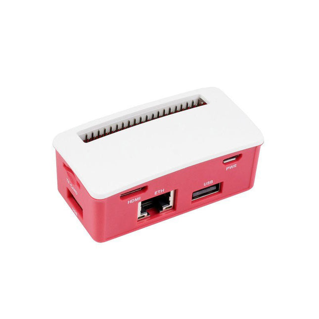
The ETH-USB-Hub-Box is a Hub kit with ETH/USB Hub HAT (B) inside. It is tailored for Raspberry Pi Zero series, small in size, each cut-out of the case is exactly aligned with the connector. The case adopts classic Raspberry Pi red/white color combination, with quality dull polish surface, effectively keeping the Zero away from dust. This Hub Box will provide RJ45 Ethernet port and more USB capability for your Zero, make it easy to connect the Internet and sorts of USB devices.
Features
Designed for Raspberry Pi Zero, compatible with Zero series boards
3x extended USB ports, compatible with USB 2.0 / 1.1
Incorporates RTL8152B Ethernet chip, supports 1x RJ45 Ethernet port, 10/100M auto-negotiation
Pogo pin design, for direct connecting with Raspberry Pi Zero/Zero W/Zero WH
Angle rounded design, smooth hand feeling, 'simple snap' case lid
Quality ABS material, dull polish surface, anti-fingerprint
Comes with two different lids, changing as you like
Included
1x ETH/USB Hub HAT (B)
1x ABS case
4x Rubber feets
1x Screws pack
1x Screwdriver
Downloads
Documentation
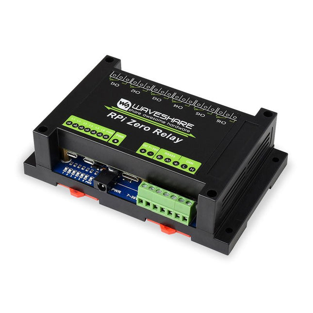
This Industrial 6-Channel Relay Module is suitable for Raspberry Pi Zero with pre-soldered pinheader. It provides RS485/CAN Bus, Power Supply Isolation, and Photocoupler Isolation.Features
RS485 half-duplex communication: using SP3485, UART control, auto RX/TX switch
CAN half-duplex communication: using MCP2515 + SN65HVD230 solution, SPI control
Onboard unibody power supply isolation, provides stable isolated voltage, needs no extra power supply for the isolated terminal
Onboard photocoupler isolation, prevent interference from external high-voltage circuit connected to the relay
Onboard TVS (Transient Voltage Suppressor), effectively suppress surge voltage and transient spike voltage in the circuit, lightningproof & anti-electrostatic
Onboard resettable fuses and protection diodes, ensuring current/voltage stable output, preventing over current/voltage, better shock-resistance performance
High quality relay, contact rating: ≤10A 250V AC or ≤10A 30V DC
ABS protection enclosure with rail-mount support, easy to install, safe to use
Comes with development resources and manual (wiringPi and python examples)
Specifications
Operating voltage: 7~36 V (industrial input voltage compatible)
Relay channel: 6ch
Communication Protocol: RS485, CAN
Contact form: 1NO 1NC
Included
1x ABS protection enclosure (top and bottom)
1x RPi Zero Relay
1x Screwdriver
1x OPTIONS 12 V, 1 A power adapter
1x Screws pack
DownloadsDocumentation
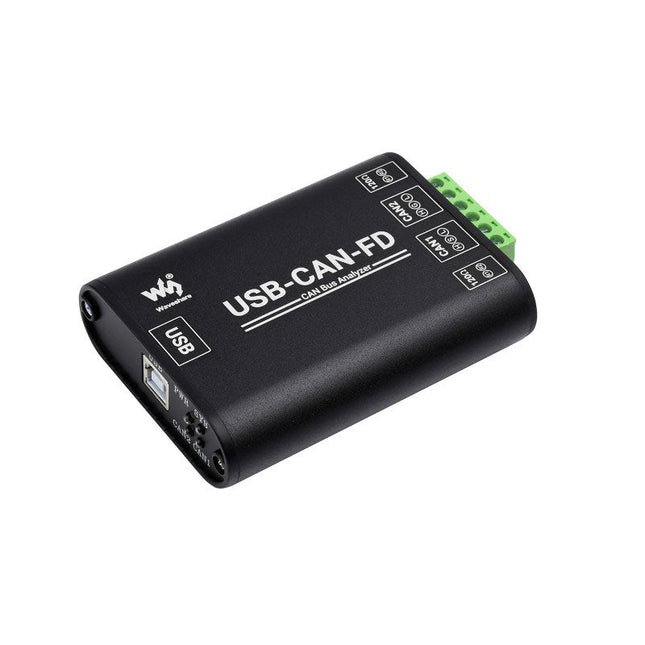
The USB-CAN-FD is an industrial-grade high-performance USB to CAN-FD adapter, CAN/CAN-FD bus communication interface card, and CAN/CAN-FD protocol data analyzer. Onboard dual independent CAN-FD interfaces with electrical isolation and multiple protection circuits. Supports Windows system, comes with drivers, CAN-FD Tools related software, secondary development examples, and tutorials. It can be connected to the PC or industrial control host via a USB port to realize transceiver control, data analysis, collection and monitoring of CAN/CAN-FD bus network. It is compact in size and easy to use, which can be used for learning and debugging of CAN/CAN-FD bus, as well as for secondary development and integration into various industrial, power communication, and intelligent control applications that require CAN/CAN-FD bus communication. Specifications Product type Industrial grade: USB to CAN-FD interface converter, CAN/CAN-FD bus communication interface card, CAN/CAN-FD protocol data analyzer USB Operating voltage 5 V (directly powered by USB port without external power supply) Connector USB-B CAN/CAN FD interface CAN/CAN FD channel Dual-channel: CAN1 and CAN2 (independent and full-isolated, isolated voltage: 3000 V DC) Connector CAN bus screw terminal (OPEN6 5.08 mm pitch) Terminal resistor Each CAN/CAN-FD channel has two built-in 120Ω terminal resistors, which can be enabled by switch Baud Rate 100Kbps~5Mbps (configurable via software) Protocol Support CAN2.0A, CAN2.0B, and ISO 11898-1 CAN-FD protocol V.1.0 Transfer speed The receiving and sending speed of each CAN/CAN-FD channel can reach 20000 frames/s and 5000 frames/s Transmit buffer 1500 frames receiving buffer and 64 frames sending buffer per channel (automatically retransmit when the transmission fails) Indicators PWR Power indicator SYS System status indicator, normally off; keeps on when there is a bus error CAN1 CAN1 channel indicator (blinking when sending and receiving data) CAN2 CAN2 channel indicator (blinking when sending and receiving data) System support Windows Windows XP/7/8/10/11 (32/64 bits); Does Not support the Linux system now, and the related drivers are under development. Operating temperature −40 to +85°C Case material Aluminum alloy case + 3D flame-retardant insulating sheets on both sides (This design can provide better protection against metal tip discharge, also improves product safety, and extends service life) Dimensions 104 x 70 x 25 mm Included Waveshare USB-CAN-FD USB-A to USB-B cable 4-pin cable Screwdriver Downloads Wiki
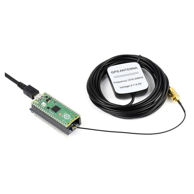
The Pico-GPS-L76B is a GNSS module designed for Raspberry Pi Pico, with multi satellite systems support including GPS, BDS, and QZSS. It has advantages such as fast positioning, high accuracy, and low power consumption, etc. Combined with the Raspberry Pi Pico, it's easy to use global navigating function.
Features
Standard Raspberry Pi Pico header, supports Raspberry Pi Pico series boards
Multi satellite systems support: GPS, BDS, and QZSS
EASY, self track prediction technology, help quick positioning
AlwaysLocate, intelligent controller of periodic mode for power saving
Supports D-GPS, SBAS (WAAS/EGNOS/MSAS/GAGAN)
UART communication baudrate: 4800~115200bps (9600bps by default)
Onboard battery holder, supports ML1220 rechargeable cell, for preserving ephemeris information and hot starts
4x LEDs for indicating the module operating status
Comes with development resources and manual (Raspberry Pi Pico C/C++ and MicroPython examples)
Specifications
GNSS
Frequency band:GPS L1 (1575.42 Mhz)BD2 B1 (1561.098 MHz)
Channels: 33 tracking ch, 99 acquisition ch, 210 PRN ch
C/A code
SBAS: WAAS, EGNOS, MSAS, GAGAN
Horizontal position accuracy(autonomous positioning)
<2.5 m CEP
Time-To-First-Fix @ -130 dBm(EASY enabled)
Cold starts: <15s
Warm starts: <5s
Hot starts: <1s
Sensitivity
Acquisition: -148 dBm
Tracking: -163 dBm
Re-acquisition: -160 dBm
Dynamic performance
Altitude (max): 18000 m
Velocity (max): 515 m/s
Acceleration (max): 4 g
Others
Communication interface
UART
Baudrate
4800~115200bps (9600bps by default)
Update rate
1 Hz (default), 10 Hz (max)
Protocols
NMEA 0183, PMTK
Power supply voltage
5 V
Operating current
13 mA
Overall current consumption
< 40 mA@5 V (Continue mode)
Operating temperature
-40℃ ~ 85℃
Dimensions
52 × 21 mm
Included
1x Pico-GPS-L76B
1x GPS Antenna
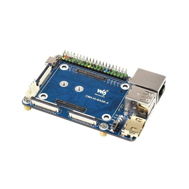
Specifications
CM4 socket
Suitable for all variants of Compute Module 4
Networking
Gigabit Ethernet RJ45 connectorM.2 M KEY, supports communication modules or NVME SSD
Connector
Raspberry Pi 40-PIN GPIO header
USB
2x USB 2.0 Type A2x USB 2.0 via FFC connector
Display
MIPI DSI display port (15-pin 1.0 mm FPC connector)
Camera
2x MIPI CSI-2 camera port (15-pin 1.0 mm FPC connector)
Video
2x HDMI port (including one port via FFC connector), supports 4K 30fps output
RTC
N/A
Storage
MicroSD card socket for Compute Module 4 Lite (without eMMC) variants
Fan header
No fan control, 5 V
Power input
5 V
Dimensions
85 x 56 mm
Included
1x CM4-IO-BASE-A
1x SSD mounting screw
Downloads
Wiki
The Waveshare PCIe to Gigabit Ethernet and USB 3.2 Gen 1 HAT+ is an expansion board designed specifically for the Raspberry Pi 5. It enhances the Raspberry Pi's connectivity by adding three high-speed USB 3.2 Gen 1 ports and a Gigabit Ethernet port, all in a driver-free, plug-and-play setup.
Features
Based on 16-pin PCIe Interface of Raspberry Pi 5
Equipped with RTL8153B high-performance Gigabit Ethernet chip
Supports Raspberry Pi OS, Ubuntu, OpenWRT, etc.
Stable and reliable network speed
Real-time monitoring of power status
Supports USB port power control via software
Included
1x PCIe to Gigabit Ethernet USB 3.2 HAT+
1x Network cable (1.5 m)
1x 16P Cable (40 mm)
1x Standoff pack
Downloads
Wiki
This PCIe to M.2 adapter is specifically designed for the Raspberry Pi 5. It supports the NVMe protocol for M.2 SSDs, enabling fast read and write operations, and adheres to the HAT+ standard. The adapter is compatible with M.2 SSDs in the 2230 and 2242 sizes.
Included
1x PCIe to M.2 HAT+ Adapter
1x 2x20 Pin header
1x 16P cable (40 mm)
1x Standoff pack
Downloads
Wiki
The Waveshare PoE M.2 HAT+ (B) combines Power over Ethernet (PoE) and PCIe-to-M.2 functionality for the Raspberry Pi 5. It supports the IEEE 802.3af/at networking standards and accommodates M.2 NVMe SSDs in 2230, 2242, 2260, and 2280 form factors. Additionally, it enables SSD boot for the Raspberry Pi.
Features
Standard Raspberry Pi 40-pin GPIO extension header, compatible with Raspberry Pi 5
Supports Power over Ethernet (PoE) and complies with the IEEE 802.3af/at network standards
Utilizes a fully isolated Switch Mode Power Supply (SMPS) for stable power delivery
Supports NVMe protocol M.2 interface hard drives, offering high-speed read/write performance and high efficiency
Provides 1x PCIe in Gen2 or Gen3 mode
Specifically designed for the Raspberry Pi 5 only
Compatible with M.2 SSDs in 2230, 2242, 2260, and 2280 form factors
Specifications
PoE power input
37~57 V DC
Power output
GPIO header: 5 V/4.5 A (max.)2P header: 12 V/2 A (max.)
Network standard
IEEE 802.3af/at PoE
Dimensions
56 x 85 mm
Included
1x Waveshare PoE M.2 HAT+ (B)
1x 16-Pin PCIe cable
1x SSD mounting screw
1x Screws pack
Downloads
Wiki
The PicoGo is a smart mobile robot based on Raspberry Pi Pico, it includes ultrasonic module, LCD module, Bluetooth module, line following module, and obstacle avoidance module, all these functions are highly integrated for easily achieving IR obstacle avoidance, auto line following, Bluetooth/IR remote control, and more. With various advanced features, it will help you fast get started with smart robot design and development.
Features
Standard Raspberry Pi Pico header, supports Raspberry Pi Pico series
Battery protection circuit: over charge/discharge protection, over current protection, short circuit protection, reverse proof, more stable and safe operating
Recharge/Discharge circuit, allows programming/debugging concurrently while recharging
5-ch infrared sensor, analog output, combined with PID algorithm, stable line tracking
Onboard multiple smart robot sensors like line tracking, obstacle avoidance, no more messy wiring
1.14-inch IPS colorful LCD display, 240 x135 pixels, 65K colors
Integrates Bluetooth module, allows teleoperations like robot movement, RGB LED display color, buzzer, etc. by using mobile phone APP
N20 micro gearmotors, with metal gears, low noise, high accuracy
Colorful RGB LED
IR obstacle avoidance
The module sends IR beam and detects objects by receiving the reflected IR beam, to easily avoid obstacles in the way.
Auto line following
Features 5-ch IR detector for sensing and analysing the black line, combined with PID algorithm for adjusting robot movement, high sensitivity, stable tracking.
Ultrasonic sensor
Ultrasonic is generally faster and easy-to-calculate, suitable for functions like real time control, and obstacle avoidance, with the industrial practical ranging accuracy, it is widely used on robot research and development.
Object tracking
The robot is able to detect front object by ultrasonic or IR, and keeps moving to track the target automatically.
IR remote control
Integrates IR receiver, so that you can control the robot to move or turn direction by sending infrared light from the remote controller.
Bluetooth remote control
Comes with mobile phone APP, allows you to use the phone to control the movement of the robot, or control its peripherals like changing LED color, making the buzzer to sound, etc.
RGB LED control
Included
1x PicoGo base board
1x PicoGo acrylic panel
1x 1.14-inch LCD Module
1x Ultrasonic sensor x1
1x IR remote controller
1x USB-A to micro-B cable 1.2 m
1x PH2.0 8-Pin cable 5 cm opposite side headers
1x Mini cross wrench sleeve
1x Screwdriver
1x Screws and standoffs pack
Required
1x Raspberry Pi Pico (pre-soldered header)
1x 5 V/3 A power supply
2x 14500 batteries
Downloads
Wiki
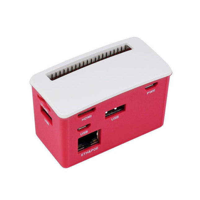
The PoE-ETH-USB-Hub-Box is a Hub kit with PoE/ETH/USB Hub HAT inside. It is tailored for Raspberry Pi Zero series, small in size, each cut-out of the case is exactly aligned with the connector. The case adopts classic Raspberry Pi red/white color combination, with quality dull polish surface, effectively keeping the Zero away from dust. By using this small Hub Box and some proper 802.3af-compliant power sourcing equipments, it is possible to provide both network connection and power supply for your Raspberry Pi Zero in only one Ethernet cable, along with 3x extended USB ports.
Features
Designed for Raspberry Pi Zero, compatible with Zero series boards
Incorporates RTL8152B Ethernet chip, with 10M / 100M auto-negotiation RJ45 port
PoE (Power over Ethernet) feature, 802.3af-compliant
Fully isolated SMPS (Switch Mode Power Supply)
3x extended USB ports, compatible with USB 2.0 / 1.1
Angle rounded design, smooth hand feeling, 'simple snap' case lid
Quality ABS material, dull polish surface, anti-fingerprint
Comes with two different lids, changing as you like
Included
1x PoE/ETH/USB Hub HAT kit
1x ABS case
4x Rubber feets
1x Screws pack
Downloads
Documentation
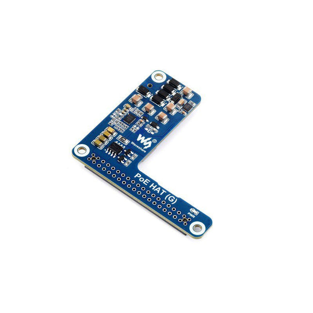
The PoE HAT (G) is an IEEE 802.3af/at-compliant PoE (Power Over Ethernet) HAT for Raspberry Pi 5. By using with a PoE router or switch that supports the IEEE 802.3af/at network standard, it is possible to provide both network connection and power supply for your Raspberry Pi in only one Ethernet cable.
Features
Standard Raspberry Pi 40-pin GPIO header
PoE capability, IEEE 802.3af/at-compliant
Onboard original IC solution for more stable PoE power performance
Adopts non-isolated switched-mode power supply (SMPS)
Compact and easy to assemble
Specifications
PoE power input
38~57 V DC in
Power output
GPIO header: 5 V/5 A (max)
Network standard
IEEE 802.3af/at PoE
Dimensions
56.5 x 64.98 mm
Included
1x PoE HAT (G)
1x 2x2 header
1x 2x20 header
1x Standoffs pack
Downloads
Wiki
This polysilicon solar panel (18 V/10 W) provides stable performance with a high conversion efficiency of >20%.
Specifications
Solar cell type
Polysilicon
Output power tolerance
±3%
Operating voltage
17.6 V
Open circuit voltage
21.6 V
Cell quantity
36 (4x9)
Power
10 Wp (max)
Conversation efficiency
>20%
Operating current
0.57 A
Short circuit current
0.61 A
Standard system voltage
1000 V (Max)
Operating temperature
-40°C ~ +85°C
Pressure on panel
30 m/s (200 kg/sq.m) (Max)
Cable
Length 90 cm, DC plug, OD 3.5 mm ID 1.35 mm
Frame material
Anodic oxidation aluminum alloy
Dimensions
340 x 232 x 17 mm
Weight
0.935 kg
The Waveshare 400 GPIO Header Extension is designed for Raspberry Pi 400 and provides a color-coded header and easy expansion.
Features
Designed for Raspberry Pi 400
Color-Coded Header
Easy Expansion
Included
1x PI400-GPIO-ADAPTER-B
1x Screws pack