The Waveshare 400 GPIO Header Extension is designed for Raspberry Pi 400 and provides a color-coded header and easy expansion.
Features
Designed for Raspberry Pi 400
Color-Coded Header
Easy Expansion
Included
1x PI400-GPIO-ADAPTER-B
1x Screws pack
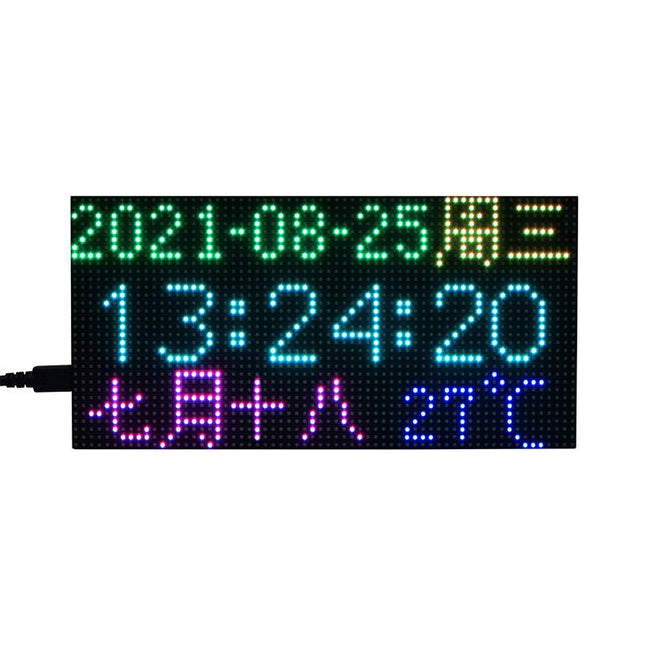
This is a RGB LED matrix digital clock designed for Raspberry Pi Pico. It incorporates high precision RTC chip DS3231, photosensor, buzzer, IR receiver, and buttons, features multiple functions including accurate electronic clock, temperature display, auto brightness adjustment, alarm, and button config. The important part is, rich open source codes and development tutorials are also provided to help you fast get started with Raspberry Pi Pico and make your own original electronic clock. Features Standard Raspberry Pi Pico header, supports Raspberry Pi Pico series Using P3 fine-pitch RGB LED matrix panel, with 2048 individual RGB LEDs, 64×32 pixels, 3 mm pitch, allows displaying text, colorful image, or animation Onboard high precision RTC chip DS3231, with backup battery holder (battery included), maintains accurate timekeeping when main power is off Real-Time Clock Counts Seconds, Minutes, Hours, Date of the Month, Month, Day of the Week, and Year with Leap-Year Compensation Valid Up to 2100 Optional format: 24-hour OR 12-hour with an AM/PM indicator 2x programable alarm clock Digital temperature sensor output: ±3°C accuracy Embedded photosensor for auto brightness adjustment due to the ambient light, power saving and eye care Embedded buzzer for alarm or hourly ring, etc. IR receiver, combined with the IR remote controller, supports IR wireless control 5x buttons for configuration, reset, and code programming Quality acrylic back panel and dimmer panel, better looking, more comfortable displaying Comes with development resources and manual (Raspberry Pi Pico C/C++ and MicroPython examples) Included 1x Pico-RGB-Matrix-P3-64x32 base board 1x RGB-Matrix-P3-64x32 LED matrix and accessories 1x Black acrylic back panel 1x Dark brown acrylic front panel 1x IR remote controller 1x Double-sided tape 1x Screws pack Downloads Documentation
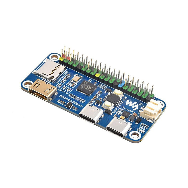
Waveshare RP2040-PiZero is a high-performance and cost-effective microcontroller board with onboard DVI interface, TF card slot and PIO-USB port, compatible with Raspberry Pi 40-pin GPIO header, easy to develop and integrate into the products.
Features
RP2040 microcontroller chip designed by Raspberry Pi
Dual-core ARM Cortex M0+ processor, flexible clock running up to 133 MHz
264 KB of SRAM, and 16 MB of onboard Flash memory
Onboard DVI interface can drive most HDMI screens (DVI compatibility required)
Supports using as a USB host or slave via onboard PIO-USB port
Onboard TF card slot for reading and writing TF card
Onboard Lithium battery recharge/discharge header, suitable for mobile scenarios
USB 1.1 with device and host support
Drag-and-drop programming using mass storage over USB
Low-power sleep and dormant modes
2x SPI, 2x I²C, 2x UART, 4x 12-bit ADC, 16x controllable PWM channels
Accurate clock and timer on-chip
Temperature sensor
Accelerated floating-point libraries on-chip
Downloads
Wiki
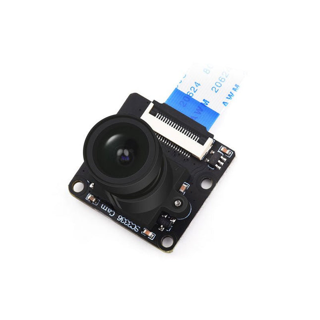
This camera module adopts a SmartSens SC3336 sensor chip with 3 MP resolution. It features high sensitivity, high SNR, and low light performance and it is capable of a more delicate and vivid night vision imaging effect, and can better adapt to ambient light changes. Also, it is compatible with Luckfox Pico series boards.
Specifications
Sensor
Sensor: SC3336
CMOS size: 1/2.8"
Pixels: 3 MP
Static resolution: 2304x1296
Maximum video frame rate: 30fps
Shutter: Rolling shutter
Lens
Focal length: 3.95 mm
Aperture: F2.0
FOV: 98.3° (diagonal)
Distortion: <33%
Focusing: Manual focus
Downloads
Wiki
This solar power management module is designed for 6~24 V solar panel. It can charge the 3.7 V rechargeable Li battery through solar panel or USB connection, and provides 5 V/1 A or 3.3 V/1 A regulated output. The module features MPPT (Maximum Power Point Tracking) function and multi protection circuits, therefore, it is able to keep working with high-efficiency, stability, and safety. It is suited for solar powered, low-power IoT, and other environmental protection projects. Features Supports MPPT (Maximum Power Point Tracking) function, maximizing the efficiency of the solar panel Supports solar panel / USB connection battery charging For 6~24 V solar panel, DC-002 jack input or screw terminal input Onboard MPPT SET switch, select the level closed to input level to improve charging efficiency Onboard two power output interfaces: USB port for 5 V output, pinheader for 3.3 V or 5 V output Onboard high capacity aluminum electrolytic capacitor and SMD ceramic capacitor, reducing the ripple, stable performance 14500 battery holder and PH2.0 battery connector, for connecting multi kinds of 3.7 V rechargeable Li battery Several LED indicators, for monitoring the status of solar panel and battery Multi protection circuits: over charge / over discharge / reverse protection / over heat / over current, stable and safe to use Specifications Solar In 6~24 V (6 V by default) Recharging USB Battery 3.7 V 850mAh 14500 Li-ion battery (NOT included) USB input 5 V (Micro USB) 5 V output 5 V/1 A (USB OUT, pin header) 3.3 V/1 A (pin header) Recharging cutoff voltage 4.2 V ±1% Over discharging protection voltage 2.9 V ±1% Solar panel recharging efficiency ~78% USB recharging efficiency ~82% Batteries boost outout efficiency ~86% Quiescent current (max) <2 mA Operating temperature -40°C ~ 85°C Dimensions 65.2 x 56.2 x 22.9 mm Note: 14500 battery is NOT included. Downloads Wiki
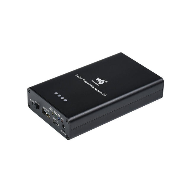
The Solar Power Manager is compatible with general 6~24 V solar panels. It can recharge the 18650 rechargeable Li-ion batteries through solar panel or USB TYPE-C connection, and provides 5 V/3 A regulated output (with multi protocols support including PD/QC/FCP/PE/SFCP). The module features MPPT (Maximum Power Point Tracking) function and multi protection circuits, therefore, it is able to keep operating with high-efficiency, stability, and safety. It is suitable for solar powered, low-power IoT, and other environmental protection projects. Features Supports MPPT (Maximum Power Point Tracking) function, maximizing the efficiency of the solar panel Flexible battery recharging: from solar panel or USB-C power adapter Compatible with 6~24 V solar panels, DC-002 jack input or screw terminal input Onboard MPPT SET switch, select the level closed to input level to improve recharging efficiency Onboard aluminum electrolytic capacitor and SMD ceramic capacitor, reducing the ripple, stable performance Embedded battery holder, supports 3x 18650 rechargeable Li-ion batteries Several LED indicators, for monitoring the status of solar panel and battery Multi protection circuits: over charge / over discharge / reverse-proof / over heat / over current, stable and safe to use Specifications Solar In 6~24 V (1 V by default) Recharging USB Battery 3x 18650 Li-ion battery (NOT included) USB input 5 V (USB-C, with PD quick charge support) 5 V output 5 V/3 A (USB-OUT, USB-C) Recharging cutoff voltage 4.2 V ±1% Over discharging protection voltage 3.0 V ±1% Solar panel recharging efficiency ~78% USB recharging efficiency ~93% Batteries boost outout efficiency ~90% Quiescent current (max) <2 mA Case Metal case Operating temperature -40°C ~ 85°C Dimensions 119.0 x 71.0 x 25.2 mm Included 1x Solar Power Manager (C) 1x Adapter Downloads Wiki
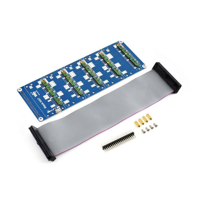
This is an I/O expansion kit designed for Raspberry Pi, which provides 5 sets of 2x20 pinheaders, that means a handy way to 'stack' multi different HATs together, and use them as a specific combination / project.
Features
Standard Raspberry Pi connectivity, directly pluggable OR through ribbon cable
5 sets of 2x20 pinheaders, connect multi HATs together
USB external power port, provides enough power supply for multi HATs
Clear and descriptive pin labels for easy use
Reserved jumper pads on the bottom side, pin connections are changeable by soldering, to avoid pin conflicts
Note: make sure there are no any pin conflicts between the HATs you want to use together before connecting.
Specifications
Dimensions: 183 × 65 mm
Mounting hole size: 3 mm
Included
1x Stack HAT
1x Ribbon cable 40-Pin
1x 2x20 male pinheader
1x RPi screws pack (4pcs) x1
WCH CH32V307 RISC-V development board features 8 UART ports controlled over Ethernet The CH32V307 is an interconnected microcontroller, based on 32-bit RISC-V core, with hardware stack area and fast interrupt entry. Compared with standard RISC-V, the interrupt response speed is greatly improved. With single-precision float point instruction sets added and stack area extended, the CH32V307 has higher performance, the number of U(S)ART is extended to 8, and the number of motor timer is extended to 4. The CH32V307 provides USB2.0 high-speed interface (480 Mbps) and has built-in PHY transceiver. Ethernet MAC is upgraded to GbE and integrates 10M PHY module. Features RISC-V4F processor, max 144 MHz system clock frequency Single-cycle multiplication and hardware division, hardware float point unit (FPU) 64KB SRAM, 256 KB Flash Supply voltage: 2.5 V/3.3 V, GPIO unit is supplied independently Multiple low-power modes: sleep/stop/standby Power-on/power-down reset (POR/PDR), programmable voltage detector (PVD) 2 general DMA controllers, 18 channels in total 4 amplifiers Single true random number generator (TRNG) 2x 12-bit DAC 2-unit 16-channel 12-bit ADC, 16-channel TouchKey 10 timers USB2.0 full-speed OTG interface USB2.0 high-speed host/device interface (built-in 480 Mbps PHY) 3 USARTs, 5 UARTs 2 CAN interfaces (2.0B active) SDIO interface, FSMC interface, DVP 2x I²C, 3x SPI, 2x I²S 80 I/O ports, can be mapped to 16 external interrupts CRC calculation unit, 96-bit unique chip ID Serial 2-wire debug interface Packages: LQFP64M, LQFP100 Downloads Datasheet GitHub
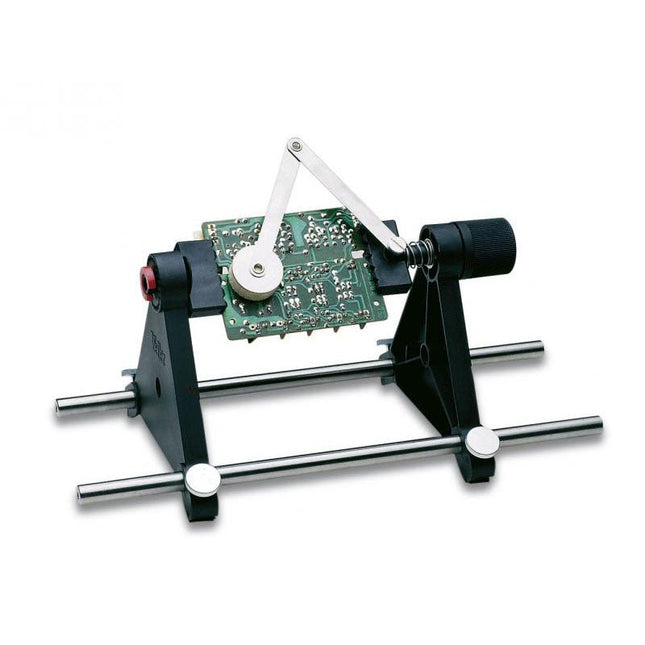
This fast mounting frame has a spring clamp, rotates through 360° in increments of 15° and has a cushioned pressure arm for keeping components in place when you flip the board upside down for soldering.
Max. size 160 x 235 mm
Rotates through 360° in increments of 15°
Spring clamp
Cushioned arm for component fixing
PCB holder
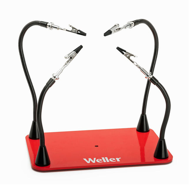
Free up your hands and secure and protect your soldering projects with Weller's Helping Hands with 4 Magnetic Arms. Enjoy adjustable and flexible positions with magnetic gooseneck arms with alligator clamps that are easily positionable for multiple configurations. Applications Hobby Home repair Drone Audio repair Joining wires Engraving Jewelry making Electronics Specifications Dimensions (Base) 152 x 229 mm (6 x 9') Length (Arms) 2 arms: 216 mm (8.5')2 arms: 317 mm (12.5')
4 LEDs and 4 push buttons ensure hours of fun. Repeat the combination, harder and harder, faster and faster. The microprocessor-controlled game has 4 different difficulty levels and low consumption. The sound and/or LED indication are adjustable. To save the three 1.5 V AA batteries (not included), the kit automatically switches itself off when not in use.
Downloads
Manual
The Whadda E12 is a high-quality carbon film resistor set comprising 610 pieces, with 10 pieces for each of the 61 standard E12 series values ranging from 10 Ω to 1 MΩ. Each resistor has a power rating of 0.25 W, a tolerance of 5%, and can operate within a temperature range of -55°C to 155°C. The maximum operating voltage is 250 V.
These resistors are suitable for applications in TVs, audio and video equipment, telephone receivers, communication systems, instrumentation, and home appliances.
The Christmas tree with flashing LEDs takes the coziness of Christmas to a new level! With 16 flashing LEDs, this green Christmas tree creates a warm atmosphere. With very low power consumption and the option to be powered by a 9-volt battery (not included), this Christmas decoration is easy to use.
Enjoy the holidays with this atmospheric addition to your decoration collection.
Downloads
Manual
Valentine's Hearts, 28 blinking LEDs, romantic LED lighting Valentine's Hearts – 28 blinking LEDs for a romantic atmosphere. The perfect Valentine's gift to express your love. Battery-powered and portable, ideal for Valentine's Day.
Downloads
Manual
This educational soldering kit is suitable for all kinds of applications such as model making and works with a 9 V battery (not included). You can control the flashing speed with two potentiometers.
Downloads
Manual
The Theremin was the first music synthesizer. The Junior Theremin is our, smaller, version of that classic electronic musical instrument. As you move your hand towards and away from the wire aerial, the Theremin responds by changing the pitch of the note it is playing. It can play individual notes as well as varying the tone of a single note.
How do you use the theremin?
The wire aerial responds to the movement of your hand towards and away from it and changes the pitch of the note it plays, without actually being touched. Junior Theremin works in two modes – continuous and discrete. When you first connect the battery Junior Theremin is in continuous mode. Pressing both pushbuttons together switches between continuous and discrete modes. Discrete mode, as its name implies, plays individual or discrete notes rather than a continuously variable tone. Eight notes over a single octave are available. In discrete mode the two pushbuttons change the octave of the notes. The left-hand pushbutton (marked -) lowers the octave, and the right-hand pushbutton (marked +) raises the octave. The pushbuttons only change the octave so long as they are pressed. In continuous mode the pushbuttons have no effect.
Downloads
Manual
When playing a board game, do you find it annoying when you push away all the pawns with the dice? Or when friends try to cheat by manipulating the dice? With this soldering kit, this is a thing of the past. Instead of pressing a button, you activate this microprocessor-controlled dice by shaking. The 7 flashing LEDs run out slowly and the final combination is displayed flashing. The kit works with one CR2025 or one CR2032 button cell (not included).
Downloads
Manual
Looking for a fun DIY Christmas project? Assemble and program this extra-large Poly Reindeer figurine and make its LEDs shine all the colors of the rainbow! Ideal for both beginners and advanced makers!
This educational and fun kit combines soldering and programming skills in one XL-sized project. First, you will need to solder some simple components onto the copper plated circuit board. The components include fancy RGB LEDs that have a special diffused effect. Once the soldering work is finished, you will be able to program the colors and light effects of the different LEDs thanks to the onboard Arduino Nano Every. The Arduino will be pre-programmed with some basic LED effects, so your kit will work once you power it with the included adaptor. Or you can choose to write your own code based on the available example code.
Programmable add-ons
The printed circuit board of this project is designed especially so you can add different add-ons. For example, add an OLED screen to display messages or program it to countdown the days until Christmas! Or add an IoT Tuya chip so your project can communicate with your smartphone. You can even add a sound microphone, motion sensor or light sensor.
Features
XL-sized & copper plated circuit board (PCB) in the shape of a polymetric reindeer
22 addressable (programmable) RGB LEDs
14 x 5 mm RGB LEDs
10 x 8 mm RGB LEDs
Arduino Nano Every
Onboard push button
USB A to USB micro cable for programming
USB A to USB B cable for power supply
Wooden holder
Complete manual and video available in 5 languages
Example code for Arduino available
Educational & fun for all ages and skill levels
Expandable with lots of add-ons:
an OLED screen
a smart IoT sensor to connect with your smartphone
a microphone sensor
and more!
Not included: soldering iron, soldering tin, pliers and an soldering mat
Specifications
Dimensions: 168 x 270 mm
Power supply: 5 V/2.1 A max. (cable included)
From Theory to Practical Applications in Wireless Energy Transfer and Harvesting
Wireless power transmission has gained significant global interest, particularly with the rise of electric vehicles and the Internet of Things (IoT). It’s a technology that allows the transfer of electricity without physical connections, offering solutions for everything from powering small devices over short distances to long-range energy transmission for more complex systems.
Wireless Power Design provides a balanced mix of theoretical knowledge and practical insights, helping you explore the potential of wireless energy transfer and harvesting technologies. The book presents a series of hands-on projects that cover various aspects of wireless power systems, each accompanied by detailed explanations and parameter listings.
The following five projects guide you through key areas of wireless power:
Project 1: Wireless Powering of Advanced IoT Devices
Project 2: Wireless Powered Devices on the Frontline – The Future and Challenges
Project 3: Wireless Powering of Devices Using Inductive Technology
Project 4: Wireless Power Transmission for IoT Devices
Project 5: Charging Robot Crawler Inside the Pipeline
These projects explore different aspects of wireless power, from inductive charging to wireless energy transmission, offering practical solutions for real-world applications. The book includes projects that use simulation tools like CST Microwave Studio and Keysight ADS for design and analysis, with a focus on practical design considerations and real-world implementation techniques.
Features RP2040 microcontroller with 2 MB Flash Dual-core cortex M0+ at up to 133 MHz 264 KB multi-bank high performance SRAM External Quad-SPI Flash with eXecute In Place (XIP) High performance full-crossbar bus fabric 30 multi-function General Purpose IO (4 can be used for ADC) 1.8-3.3 V IO Voltage (NOTE. Pico IO voltage is fixed at 3.3 V) 12-bit 500 ksps Analogue to Digital Converter (ADC) Various digital peripherals 2× UART, 2× I²C, 2× SPI, 16× PWM channels 1× Timer with 4 alarms, 1× Real Time Counter 2× Programmable IO (PIO) blocks, 8 state machines total Flexible, user-programmable high-speed IO Can emulate interfaces such as SD Card and VGA Includes W5100S Supports Hardwired Internet Protocols: TCP, UDP, WOL over UDP, ICMP, IGMPv1/v2, IPv4, ARP, PPPoE Supports 4 Independent Hardware SOCKETs simultaneously Internal 16 KB Memory for TX/ RX Buffers SPI Interface Micro-USB B port for power and data (and for reprogramming the Flash) 40 pin 21x51 'DIP' style 1mm thick PCB with 0.1' through-hole pins also with edge castellations 3-pin ARM Serial Wire Debug (SWD) port 10 / 100 Ethernet PHY embedded Supports Auto Negotiation Full / Half Duplex 10 / 100 Based Built-in RJ45 (RB1-125BAG1A) Built-in LDO (LM8805SF5-33V) Downloads RP2040 Datasheet W5100S Datasheet Schematic & Part list & Gerber File C/C++ Examples CircuitPython Examples
W6100-EVB-Pico is a microcontroller evaluation board based on the Raspberry Pi RP2040 and fully hardwired TCP/IP controller W6100 – and basically works the same as Raspberry Pi Pico board but with additional Ethernet via W6100. Features RP2040 microcontroller with 2 MByte Flash Dual-core cortex M0+ at up to 133 MHz 264 kByte multi-bank high performance SRAM External Quad-SPI Flash with eXecute In Place (XIP) High performance full-crossbar bus fabric 30 multi-function General Purpose I/O (4 can be used for ADC) 1.8-3.3 V I/O voltage (Note: Pico I/O voltage is fixed at 3.3 V) 12-bit 500 ksps Analogue to Digital Converter (ADC) Various digital peripherals 2x UART, 2x I²C, 2x SPI, 16x PWM channels 1x Timer with 4 alarms, 1x Real Time Counter 2x Programmable IO (PIO) blocks, 8 state machines total Flexible, user-programmable high-speed I/O Can emulate interfaces such as SD card and VGA Includes W6100 Supports Hardwired Internet Protocols: TCP, UDP, IPv6, IPv4, ICMPv6, ICMPv4, IGMP, MLDv1, ARP, PPPoE Supports 8 independent SOCKETs simultaneously with 32 KB memory Internal 16 Kbytes Memory for TX/RX Buffers SPI Interface Micro-USB B port for power and data (and for reprogramming the Flash) 40-pin 21x51 ‘DIP’ style 1 mm thick PCB with 0.1' through-hole pins also with edge castellations 3-pin ARM Serial Wire Debug (SWD) port 10 / 100 Ethernet PHY embedded Supports Auto Negotiation Full / Half Duplex 10 / 100 Based Built-in RJ45 (RB1-125BAG1A) Built-in LDO (LM8805SF5-33V) Downloads Documents Getting started on GitHub Firmware