This tool set contains essential tools for all kinds of electronic work.
Included
Soldering iron
Desoldering pump
Precision screwdriver 2.5x75 mm
Screwdriver 3x75 mm
Screwdriver 5x75 mm
Screwdriver 6x125 mm
Long nose plier (5')
Diagonal cutting plier (4.5')
IC extractor
Wire stripper & cutter
Multimeter
Hex key wrench
Soldering wire
Component storage box
Tweezers (Long nose)
Bag size: 340 x 210 x 50 mm
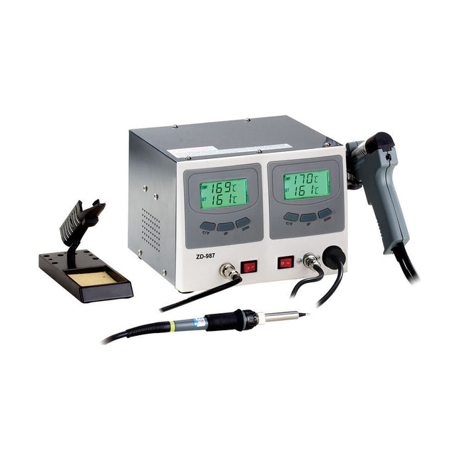
The ZD-987 Soldering & Desoldering Station is a high-performance, multifunctional tool designed for electronic product research, manufacturing, and rework. It is ideal for use in laboratories, education, and production environments – especially for repairing and reworking electronic devices and communication equipment.
The soldering iron and desoldering gun are each controlled automatically by dedicated microprocessors. Thanks to digital control electronics, a high-precision sensor, and an efficient heat exchange system, the station ensures accurate temperature regulation at the soldering tip.
Maximum temperature accuracy and optimal thermal response under load are achieved through rapid, precise measurement within a closed-loop control circuit. This design is specifically optimized for lead-free soldering processes.
Soldering Iron
The 60 W soldering iron, compatible with a wide range of N4 series soldering tips, is suitable for virtually any task in the electronics field. Its high power output and slim design make it ideal for precise, fine-pitch soldering work.
Equipped with a PTC heating element and a sensor located directly at the soldering tip, the iron ensures fast and accurate temperature control for consistent soldering results.
Desoldering Gun
The 80 W desoldering gun, compatible with a wide range of N5 series tips, is suitable for virtually any desoldering task in the electronics field. Its high power output and ergonomic gun-type design make it perfect for precise and detailed desoldering work.
Featuring a PTC heating element and a sensor located directly at the desoldering tip, it ensures rapid and accurate temperature control for consistent performance.
Features
Ideal for production and service use
The soldering iron and desoldering gun can be operated independently or simultaneously
Dual two-line LCD readout simultaneously displays tip temperature and setpoint in °C or °F
Adjustable temperature range from 160°C to 480°C (320°F to 896°F)
Push-button up/down control for temperature setting
Specifications
Voltage
220-240 V, 50 Hz
Power
160 W
Included
1x ZD-987 Soldering & Desoldering Station (Unit)
1x Soldering iron
1x Desoldering gun
1x Soldering iron stand with sponge
1x Desoldering iron stand
4x Filters
2x Nozzles
3x Clearing tool set
1x Black air nozzle with seal ring
1x Cable
1x Manual
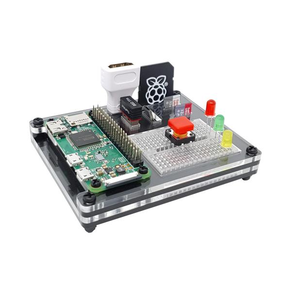
The default configuration holds a mini breadboard (included), an SD card adapter, 2x micro SD cards, 2x USB devices, a micro-USB shim and of course the Raspberry Pi Zero itself.
Users can decide to use the micro-USB shim slot to hold a micro-HDMI adapter, or you may want to hold a Portsplus or similar GPIO reference card in the SD adapter slot. You can choose to store your USB micro-SD card reader or even other larger USB devices such as the USBDoctor. Use it in whatever way works best for you.
All of the Raspberry Pi Zero ports are accessible from the ZeroDock, including the camera port and reset/composite pin header. pHATs are also not obstructed, so you’re free to prototype with your favourite add-on boards.
The case is a stylish mix of clear and black acrylic layers, black fixings and a clear breadboard, fitting in well alongside most desktop PCs/monitors.
Assembly guide available here.
Kit includes
4 layer laser-cut acrylic case
Case and Raspberry Pi fixings
Mini breadboard
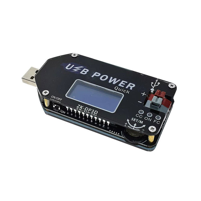
The ZK-DP3D CNC USB-C DC-DC Converter is a versatile, high-precision voltage and current regulator designed for a wide range of applications. Featuring a digital control interface with adjustable voltage (1-30 V) and current (0-2 A), it offers a precision LCD display for monitoring input/output voltage, current, power, and more.
Equipped with intelligent fast-charge protocol support (QC2.0/3.0, FCP, SCP, AFC) and multiple safety protections, it is ideal for powering devices such as USB fans, routers, and batteries. Its compact design includes push-type terminals for easy connectivity and a high power output of up to 15 W, ensuring reliability and convenience for both hobbyists and professionals.
Specifications
Input voltage
4-13 V (3 input interfaces: USB, MicroUSB and USB-C)
Output voltage
1-30 V
Output current
0-2 A
Output power
Less than 15 W
Voltage display
Resolution 0.01 V, Accuracy ±(0.5% + 3 digits)
Current display
Resolution 0.001 A, Range 0-2 A, Accuracy ±(0.5% + 3 digits)
Power display
0.00-15.00 W
Operating current
approx. 30 mA
Dimensions
92 x 40 x 16 mm
Weight
41 g
The ZY-204 is a versatile solderless breadboard with a total of 1660 tie points, perfect for building and testing electronic circuits without soldering.
It includes 2 terminal strips with 1260 tie-points and 4 distribution strips with 400 tie-points, providing ample space for complex circuit designs. 3 binding posts allow for easy connection to external power supplies.
Features
2 Terminal Strips 1260 Tie-points
4 Distribution Strips 400 Tie-points
3 Binding Posts
Black aluminum plate
Colored coordinates for easy component placement
Dimensions: 215 x 130 mm