Search results for "waveshare OR poe OR ethernet OR usb OR hub OR box OR for OR raspberry OR pi OR zero OR 3x OR usb OR 2 OR 0 OR 802 OR 3af OR compliant"
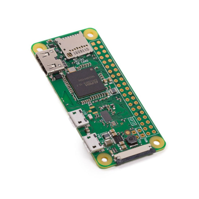
The Raspberry Pi Zero W extends the Raspberry Pi Zero family. The Raspberry Pi Zero W has all the functionality of the original Raspberry Pi Zero, but comes with added connectivity consisting of:
802.11 b/g/n wireless LAN
Bluetooth 4.1
Bluetooth Low Energy (BLE)
Other Features
1 GHz, single-core CPU
512 MB RAM
Mini HDMI and USB On-The-Go ports
Micro-USB power
HAT-compatible 40-pin header
Composite video and reset headers
CSI camera connector
Downloads
Mechanical Drawing
Schematics
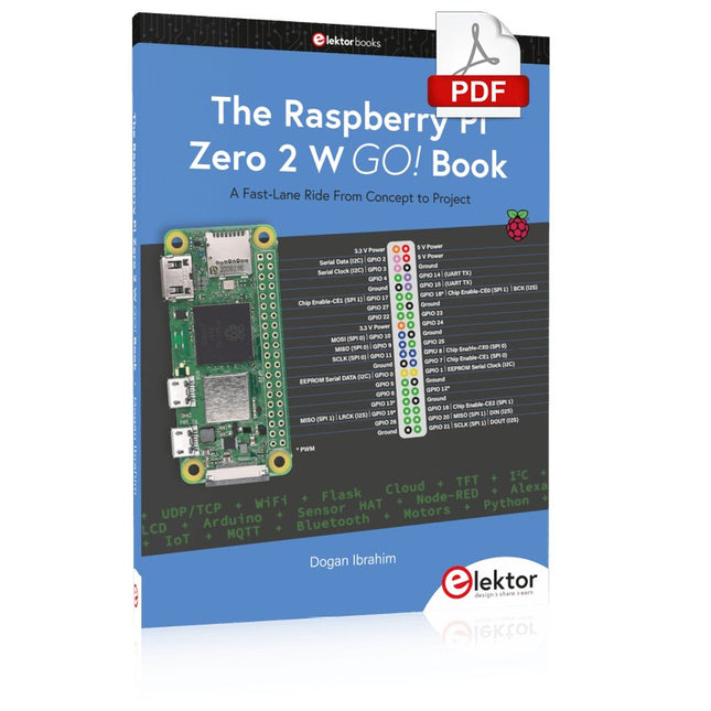
A Fast-Lane Ride From Concept to Project
The core of the book explains the use of the Raspberry Pi Zero 2 W running the Python programming language, always in simple terms and backed by many tested and working example projects. On part of the reader, familiarity with the Python programming language and some experience with one of the Raspberry Pi computers will prove helpful. Although previous electronics experience is not required, some knowledge of basic electronics is beneficial, especially when venturing out to modify the projects for your own applications.
Over 30 tested and working hardware-based projects are given in the book, covering the use of Wi-Fi, communication with smartphones and with a Raspberry Pi Pico W computer. Additionally, there are Bluetooth projects including elementary communication with smartphones and with the popular Arduino Uno. Both Wi-Fi and Bluetooth are key features of the Raspberry Pi Zero 2 W.
Some of the topics covered in the book are:
Raspberry Pi OS installation on an SD card
Python program creation and execution on the Raspberry Pi Zero 2 W
Software-only examples of Python running on the Raspberry Pi Zero 2 W
Hardware-based projects including LCD and Sense HAT interfacing
UDP and TCP Wi-Fi based projects for smartphone communication
UDP-based project for Raspberry Pi Pico W communication
Flask-based webserver project
Cloud storage of captured temperature, humidity, and pressure data
TFT projects
Node-RED projects
Interfacing to Alexa
MQTT projects
Bluetooth-based projects for smartphone and Arduino Uno communications
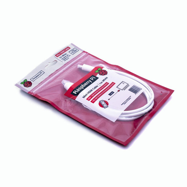
The official Raspberry Pi mini-HDMI to HDMI (A/M) cable designed for all Raspberry Pi Zero models. 19-pin HDMI Type D(M) to 19-pin HDMI Type A(M) 1 m cable (white) Nickel-plated plugs 4Kp60 compliant RoHS compliant 3 Mohm 300 VDC insulation, withstands 300 VDC for 0.1s
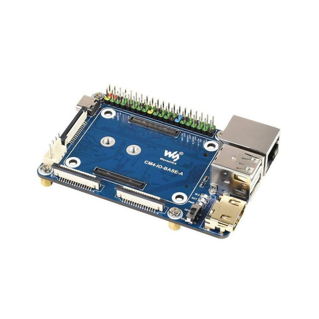
Specifications
CM4 socket
Suitable for all variants of Compute Module 4
Networking
Gigabit Ethernet RJ45 connectorM.2 M KEY, supports communication modules or NVME SSD
Connector
Raspberry Pi 40-PIN GPIO header
USB
2x USB 2.0 Type A2x USB 2.0 via FFC connector
Display
MIPI DSI display port (15-pin 1.0 mm FPC connector)
Camera
2x MIPI CSI-2 camera port (15-pin 1.0 mm FPC connector)
Video
2x HDMI port (including one port via FFC connector), supports 4K 30fps output
RTC
N/A
Storage
MicroSD card socket for Compute Module 4 Lite (without eMMC) variants
Fan header
No fan control, 5 V
Power input
5 V
Dimensions
85 x 56 mm
Included
1x CM4-IO-BASE-A
1x SSD mounting screw
Downloads
Wiki
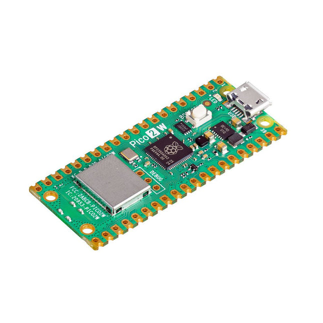
The Raspberry Pi Pico 2 W is a microcontroller board based on the RP2350 featuring 2.4 GHz 802.11n wireless LAN and Bluetooth 5.2. It gives you even more flexibility in your IoT or smart product designs and expanding the possibilities for your projects.
The RP2350 provides a comprehensive security architecture built around Arm TrustZone for Cortex-M. It incorporates signed boot, 8 KB of antifuse OTP for key storage, SHA-256 acceleration, a hardware TRNG, and fast glitch detectors.
The unique dual-core, dual-architecture capability of the RP2350 allows users to choose between a pair of industry-standard Arm Cortex-M33 cores and a pair of open-hardware Hazard3 RISC-V cores. Programmable in C/C++ and Python, and supported by detailed documentation, the Raspberry Pi Pico 2 W is the ideal microcontroller board for both enthusiasts and professional developers.
Specifications
CPU
Dual Arm Cortex-M33 or dual RISC-V Hazard3 processors @ 150 MHz
Wireless
On-board Infineon CYW43439 single-band 2.4 GHz 802.11n wireless Lan and Bluetooth 5.2
Memory
520 KB on-chip SRAM; 4 MB on-board QSPI flash
Interfaces
26 multi-purpose GPIO pins, including 4 that can be used for AD
Peripherals
2x UART
2x SPI controllers
2x I²C controllers
24x PWM channels
1x USB 1.1 controller and PHY, with host and device support
12x PIO state machines
Input power
1.8-5.5 V DC
Dimensions
21 x 51 mm
Downloads
Datasheet
Pinout
Schematic
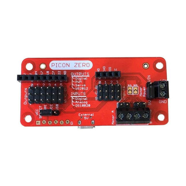
The Picon Zero is an add-on for the Raspberry Pi. It has the same size as a Raspberry Pi Zero, making it ideal to function as a pHat. Of course, it can be used on any other Raspberry Pi via a 40-pin GPIO connector.
As well as two full H-Bridge motor drivers, the Picon Zero has several Input/Output pins giving you multiple configuration options. That allows you to easily add outputs or analog inputs to your Raspberry Pi without any complicated software or kernel-specific drivers. At the same time, it opens up 5 GPIO pins from the Raspberry Pi, and it provides the interface for an HC-SR04 ultrasonic distance sensor.
The Picon Zero comes with all components, including the headers and screw terminals, fully soldered. Soldering isn't required. You can use it right out of the box.
Features
pHat format PCB: 65 mm x 30 mm
Two full H-Bridge motor drivers. Drive up to 1.5 A continuously per channel, at 3 V - 11 V.
Each motor output has both a 2-pin male header and a 2-pin screw terminal.
The motors can be powered from the Picon Zero's 5 V or an external power source (3 V - 11 V).
The Picon Zero's 5 V can be selected to be from the Raspberry Pi's 5 V line, or a USB connector on the Picon Zero. That means that you can effectively have 2 USB battery banks: one to power the servos and motors on the Picon Zero and the other to power the Pi.
4 Inputs that can accept up to 5 V. These inputs can be configured as follows:
Digital inputs
Analog inputs
DS18B20
DHT11
6 Outputs that can drive 5 V and be configured as:
Digital Output
PWM Output
Servo
NeoPixel WS2812
All Inputs and Outputs use GVS 3-pin male headers.
4-pin female header that connects directly to an HC-SR04 ultrasonic distance sensor.
8-pin female header for Ground, 3.3 V, 5 V, and 5 GPIO signals allowing you to add their additional features.
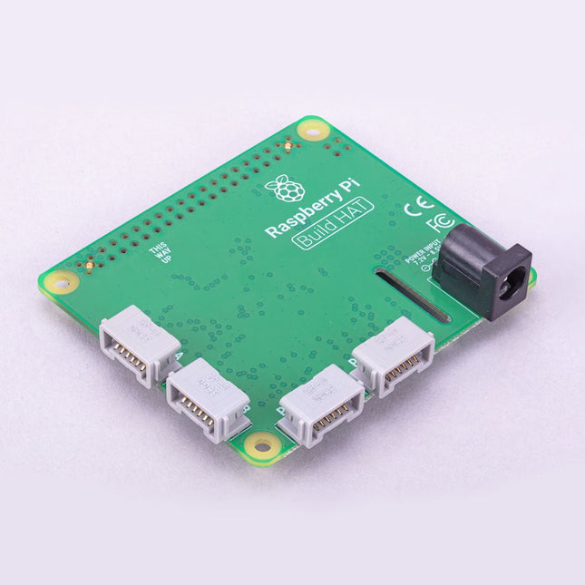
Build robust, intelligent machines that combine Raspberry Pi computing power with LEGO components.
The Raspberry Pi Build HAT provides four connectors for LEGO Technic motors and sensors from the SPIKE Portfolio. The available sensors include a distance sensor, a color sensor, and a versatile force sensor. The angular motors come in a range of sizes and include integrated encoders that can be queried to find their position.
The Build HAT fits all Raspberry Pi computers with a 40-pin GPIO header, including – with the addition of a ribbon cable or other extension device — Raspberry Pi 400. Connected LEGO Technic devices can easily be controlled in Python, alongside standard Raspberry Pi accessories such as a camera module.
Features
Controls up to 4 motors and sensors
Powers the Raspberry Pi (when used with a suitable external PSU)
Easy to use from Python on the Raspberry Pi
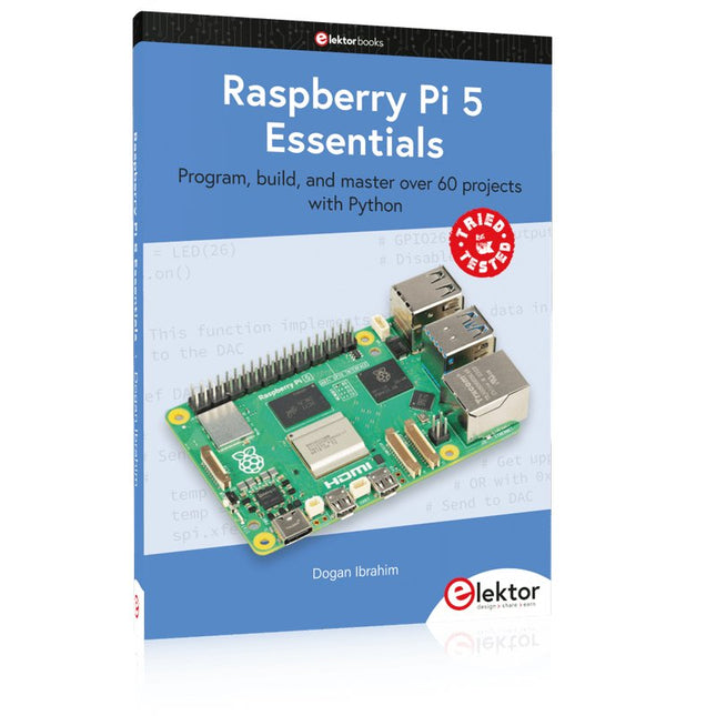
Program, build, and master over 60 projects with Python
The Raspberry Pi 5 is the latest single-board computer from the Raspberry Pi Foundation. It can be used in many applications, such as in audio and video media centers, as a desktop computer, in industrial controllers, robotics, and in many domestic and commercial applications. In addition to the well-established features found in other Raspberry Pi computers, the Raspberry Pi 5 offers Wi-Fi and Bluetooth (classic and BLE), which makes it a perfect match for IoT as well as in remote and Internet-based control and monitoring applications. It is now possible to develop many real-time projects such as audio digital signal processing, real-time digital filtering, real-time digital control and monitoring, and many other real-time operations using this tiny powerhouse.
The book starts with an introduction to the Raspberry Pi 5 computer and covers the important topics of accessing the computer locally and remotely. Use of the console language commands as well as accessing and using the desktop GUI are described with working examples. The remaining parts of the book cover many Raspberry Pi 5-based hardware projects using components and devices such as
LEDs and buzzers
LCDs
Ultrasonic sensors
Temperature and atmospheric pressure sensors
The Sense HAT
Camera modules
Example projects are given using Wi-Fi and Bluetooth modules to send and receive data from smartphones and PCs, and sending real-time temperature and atmospheric pressure data to the cloud.
All projects given in the book have been fully tested for correct operation. Only basic programming and electronics experience are required to follow the projects. Brief descriptions, block diagrams, detailed circuit diagrams, and full Python program listings are given for all projects described.
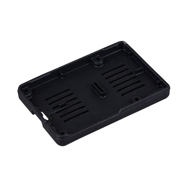
The Raspberry Pi Bumper is a snap-on silicone cover that protects the bottom and edges of the Raspberry Pi 5.
Features
One-piece flexible silicone rubber bumper
Enables easy access to the power button
Mounting holes remain accessible underneath the bumper
Downloads
Datasheet
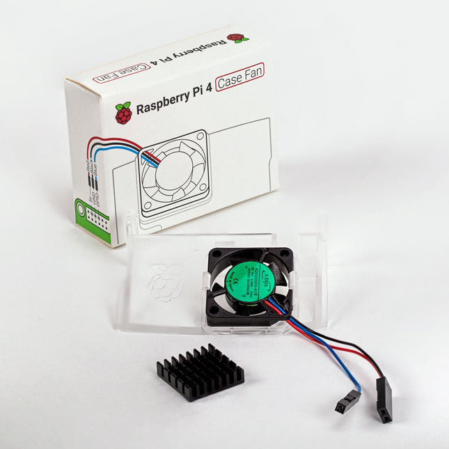
Designed for overclockers and other power users, this fan keeps your Raspberry Pi 4 at a comfortable operating temperature even under heavy load. The temperature-controlled fan delivers up to 1.4 CFM of airflow over the processor, memory, and power management IC. The bundled heatsink (18 x 8 x 10 mm) with self-adhesive pad improves heat transfer from the processor. The Raspberry Pi 4 Case Fan works with Raspberry Pi 4 and the official Raspberry Pi 4 case.
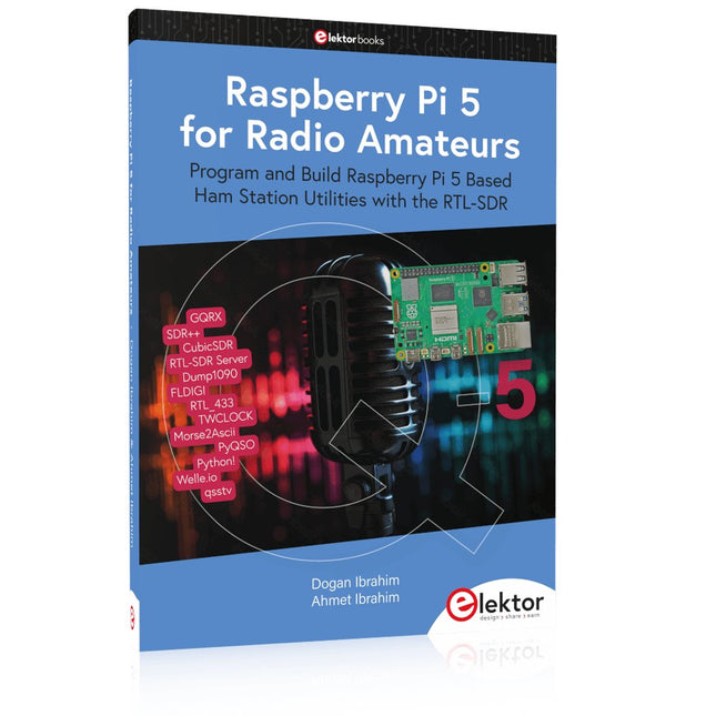
Program and Build Raspberry Pi 5 Based Ham Station Utilities with the RTL-SDR
The RTL-SDR devices (V3 and V4) have gained popularity among radio amateurs because of their very low cost and rich features. A basic system may consist of a USB based RTL-SDR device (dongle) with a suitable antenna, a Raspberry Pi 5 computer, a USB based external audio input-output adapter, and software installed on the Raspberry Pi 5 computer. With such a modest setup, it is possible to receive signals from around 24 MHz to over 1.7 GHz.
This book is aimed at amateur radio enthusiasts and electronic engineering students, as well as at anyone interested in learning to use the Raspberry Pi 5 to build electronic projects. The book is suitable for both beginners through experienced readers. Some knowledge of the Python programming language is required to understand and eventually modify the projects given in the book. A block diagram, a circuit diagram, and a complete Python program listing is given for each project, alongside a comprehensive description.
The following popular RTL-SDR programs are discussed in detail, aided by step-by-step installation guides for practical use on a Raspberry Pi 5:
SimpleFM
GQRX
SDR++
CubicSDR
RTL-SDR Server
Dump1090
FLDIGI
Quick
RTL_433
aldo
xcwcp
GPredict
TWCLOCK
CQRLOG
klog
Morse2Ascii
PyQSO
Welle.io
Ham Clock
CHIRP
xastir
qsstv
flrig
XyGrib
FreeDV
Qtel (EchoLink)
XDX (DX-Cluster)
WSJT-X
The application of the Python programming language on the latest Raspberry Pi 5 platform precludes the use of the programs in the book from working on older versions of Raspberry Pi computers.
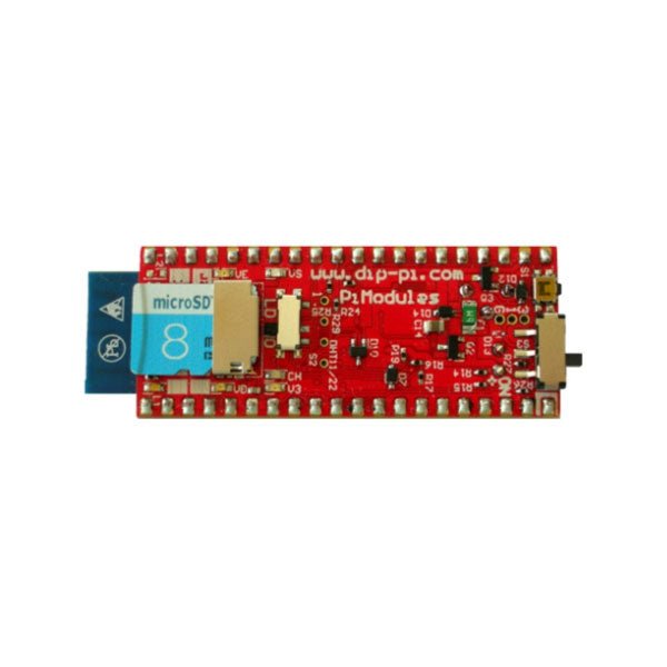
The DiP-Pi PIoT is an Advanced Powered, WiFi connectivity System with sensors embedded interfaces that cover most of possible needs for IoT application based on Raspberry Pi Pico. It can supply the system with up to 1.5 A @ 4.8 V delivered from 6-18 VDC on various powering schemes like Cars, Industrial plant etc., additionally to original micro-USB of the Raspberry Pi Pico. It supports LiPo or Li-Ion Battery with Automatic Charger as also automatic switching from cable powering to battery powering or reverse (UPS functionality) when cable powering lost. Extended Powering Source (EPR) is protected with PPTC Resettable fuse, Reverse Polarity, as also ESD.
The DiP-Pi PIoT contains Raspberry Pi Pico embedded RESET button as also ON/OFF Slide Switch that is acting on all powering sources (USB, EPR or Battery). User can monitor (via Raspberry Pi Pico A/D pins) battery level and EPR Level with PICO’s A/D converters. Both A/D inputs are bridged with 0402 resistors (0 OHM) therefore if for any reason user needs to use those Pico pins for their own application can be easy removed. The charger is automatically charging connected battery (if used) but in addition user can switch charger ON/OFF if their application needs it.
DiP-Pi PIoT can be used for cable powered IoT systems, but also for pure Battery Powered System with ON/OFF. Each powering source status is indicated by separate informative LEDs (VBUS, VSYS, VEPR, CHGR, V3V3).
User can use any capacity of LiPo or Li-Ion type; however, must take care to use PCB protected batteries with max discharge current allowed of 2 A. The embedded battery charger is set to charge battery with 240 mA current. This current is set by resistor so if user need more/less can himself to change it. The DiP-Pi PIoT is also equipped with WiFi ESP8266 Clone module with embedded antenna. This feature open a wide range of IoT applications based on it.
In Addition to all above features DiP-Pi PIoT is equipped with embedded 1-wire, DHT11/22 sensors, and micro–SD Card interfaces. Combination of the extended powering, battery, and sensors interfaces make the DiP-Pi PIoT ideal for IoT applications like data logger, plants monitoring, refrigerators monitoring etc.
DiP-Pi PIoT is supported with plenty of ready to use examples written in Micro Python or C/C++.
Specifications
General
Dimensions 21 x 51 mm
Raspberry Pi Pico pinout compatible
Independent Informative LEDs (VBUS, VSYS, VEPR, CHGR, V3V3)
Raspberry Pi Pico RESET Button
ON/OFF Slide Switch acting on all powering sources (USB, EPR, Battery)
External Powering 6-18 VDC (Cars, Industrial Applications etc.)
External Power (6-18 VDC) Level Monitoring
Battery Level Monitoring
Inverse Polarity Protection
PPTC Fuse Protection
ESD Protection
Automatic Battery Charger (for PCB protected LiPo, Li-Ion – 2 A Max) Automatic/User Control
Automatic Switch from Cable Powering to Battery Powering and reverse (UPS Functionality)
Various powering schemes can be used at the same time with USB Powering, External Powering and Battery Powering
1.5 A @ 4.8 V Buck Converter on EPR
Embedded 3.3 V @ 600 mA LDO
ESP8266 Clone WiFi Connectivity
ESP8266 Firmware Upload Switch
Embedded 1-wire Interface
Embedded DHT-11/22 Interface
Powering Options
Raspberry Pi Pico micro-USB (via VBUS)
External Powering 6-18 V (via dedicated Socket – 3.4/1.3 mm)
External Battery
Supported Battery Types
LiPo with protection PCB max current 2A
Li-Ion with protection PCB max current 2A
Embedded Peripherals and Interfaces
Embedded 1-wire interface
Embedded DHT-11/22 Interface
Micro SD Card Socket
Programmer Interface
Standard Raspberry Pi Pico C/C++
Standard Raspberry Pi Pico Micro Python
Case Compatibility
DiP-Pi Plexi-Cut Case
System Monitoring
Battery Level via Raspberry Pi Pico ADC0 (GP26)
EPR Level via Raspberry Pi Pico ADC1 (GP27)
Informative LEDs
VB (VUSB)
VS (VSYS)
VE (VEPR)
CH (VCHR)
V3 (V3V3)
System Protection
Direct Raspberry Pi Pico Hardware Reset Button
ESD Protection on EPR
Reverse Polarity Protection on EPR
PPTC 500 mA @ 18 V fuse on EPR
EPR/LDO Over Temperature protection
EPR/LDO Over Current protection
System Design
Designed and Simulated with PDA Analyzer with one of the most advanced CAD/CAM Tools – Altium Designer
Industrial Originated
PCB Construction
2 ozcopper PCB manufactured for proper high current supply and cooling
6 mils track/6 mils gap technology 2 layers PCB
PCB Surface Finishing – Immersion Gold
Multi-layer Copper Thermal Pipes for increased System Thermal Response and better passive cooling
Downloads
Datasheet
Manual