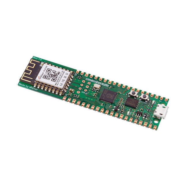
Raspberry Pi Pico EVB combined with the WizFi360-PAWizFi360-EVB-Pico is based on Raspberry Pi RP2040 and adds Wi-Fi connectivity using WizFi360. It is pin-compatible with Raspberry Pi Pico board and can be used for IoT Solution development.Specifications
RP2040 microcontroller with 2 MByte Flash
Dual-core cortex M0+ at up to 133 MHz
264 kByte multi-bank high performance SRAM
External Quad-SPI Flash with eXecute In Place (XIP)
Includes WizFi360-PA
Supports Hardwired Internet Protocols: TCP, UDP, WOL over UDP, ICMP, IGMPv1/v2, IPv4, ARP, PPPoE
WiFi 2.4G, 802.11 b/g/n
Support Station / SoftAP / SoftAP+Station operation modes
Support “Data pass-through” and “AT command data transfer” mode
Support serial AT command configuration
Support TCP Server / TCP Client / UDP operating mode
Support configuration of operating channel 0 ~ 13
Support auto 20 MHz / 40 MHz bandwidth
Support WPA_PSK / WPA2_PSK encryption
Support built-in unique MAC address and user configurable
Industrial grade (operating temperature range: -40°C ~ 85°C)
CE, FCC certification
Includes 16 Mbit Flash Memory
Micro-USB B port for power and data (and for reprogramming the Flash)
40 pin 21×51 ‘DIP’ style 1mm thick PCB with 0.1' through-hole pins also with edge castellations
3-pin ARM Serial Wire Debug (SWD) port
Built-in LDO
DownloadsDocumentation
After power on, YDLIDAR G4 start rotating and scanning the environment around it. The scanning distance is 16 m and the device offers a scanning rate of 9,000 times per second.
It makes detailed examinations of its environment and can locate the smallest of objects surrounding it. Featuring a high-precision brushless motor and encoder disc mounted on bearings, it rotates smoothly and has a service life of up to 500,000 hours of operation.
The G4 is an inexpensive solution for projects that require obstacle detection, obstacle avoidance, and/or simultaneous localization and mapping (SLAM). All YDLIDAR products are ROS ready.
Features
360 degree 2D range scanning
Stable performance, high precision
16 m range
Strong resistance to environmental light interference
Brushless motor drive, stable performance
FDA Laser safety standard Class I
360 degree omnidirectional scanning, 5-12 Hz adaptive scanning frequency
OptoMagnetic technology
Wireless data communication
Scanning rate of 9000 Hz
Downloads
Datasheet
User Manual
Development Manual
SDK
Tool
ROS
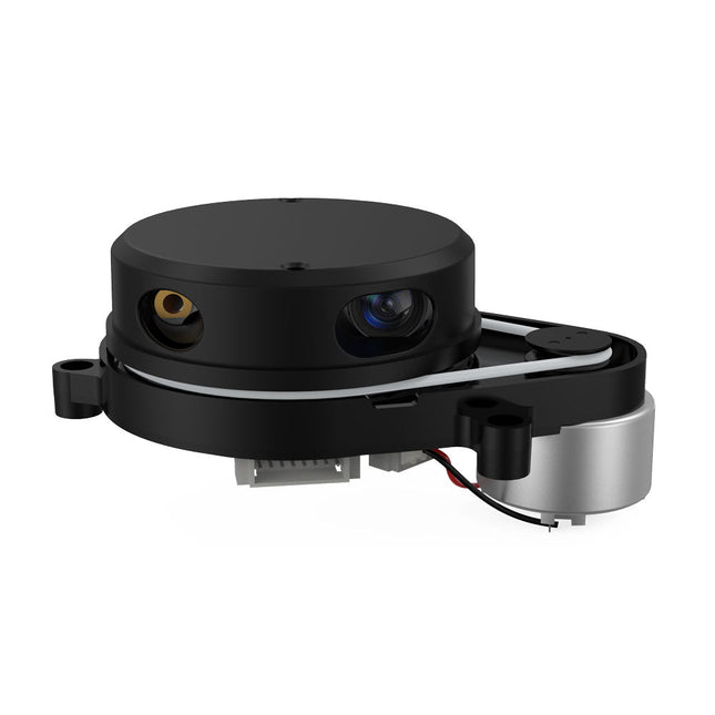
This camera adopts binocular structured light 3D imaging technology to obtain depth images and realize the function of depth information modeling. It is equipped with a dedicated depth computing chip and is specially optimized for robot obstacle avoidance.
The camera is compact in size, easy to integrate, with USB2.0 standard output interface, providing users with a high degree of flexibility. It can be adapted to complex environments such as all-black environment, indoors with strong light or weak light, backlight or smooth light, even semi-outdoors, which has a wide range of applications.
Features
Offers 1280 x 920 high-resolution image output
Uses the binocular structured light 3D imaging technology
Fearless ambient light interference
Deep calculation processors use high-performance dedicated chips
USB2.0 standard output interface
Specifications
Detection distance: 20-250 cm
Accuracy Error: <1.5 cm
Resolution: 1280 x 920 Pixel
HFOV: 78 ±3°
VFOV: 60 ±3°
Power: 1.5 W
Active Light Source: Spectrum: 830-850 nm | Power: <1.5 W
Dust-proof and Waterproof: IP65
ESD: Contact Discharge: ±8 KV | Antiaircraft: ±12 KV
Interface: USB2.0
Operating Temperature: -10~50°C
Operating Humidity: 0~80 RH
Storage Temperature: -20~80°C
Weight: 96 g
Downloads
Datasheet
User Manual
Development Manual
SDK
Tool
ROS
YDLIDAR SDM18 is a high-performance single-point LiDAR. Based on the principle of ToF, it is equipped with related optics, electricity, and algorithm design to achieve high-precision laser distance measurement and outputting high frame rate point cloud data of the scanning environment. It can be used for UAV alt-hold, robot obstacle avoidance and navigation, etc.
Specifications
High Ranging frequency: 50-250 Hz
Range Distance: 0.2-18 m
FDA Class I eye safety standard
Support UART and I²C interfaces
Dimensions: 21 x 15 x 7.87 mm
Weight: 1.35 g
Applications
UAV alt-hold and obstacle avoidance
Robot obstacle avoidance
Intelligent equipment obstacle avoidance
Navigation and obstacle avoidance of home service robots / robot vacuum cleaners
Downloads
Datasheet
User Manual
Development Manual
SDK
Tool
ROS
YDLIDAR TG15 is a 360-degree two-dimensional rangefinder. Based on the principle of TOF, it is equipped with related optics, electricity, and algorithm design to achieve high-frequency and high-precision distance measurement. The mechanical structure rotates 360 degrees to continuously output the angle information as well as the point cloud data of the scanning environment while ranging.
Features
360 degree omnidirectional scanning ranging distance measurement
Small distance error, stable performance and high accuracy
IP65 protection level
Strong resistance to ambient light interference
Industrial grade brush-less motor drive for stable performance
Laser power meets Class I laser safety standards
5-12 Hz adaptive scanning frequency (support customization)
Photomagnetic fusion technology to achieve wireless communication, wireless power supply
Ranging frequency up to 20 kHz (support customization)
Applications
Robot navigation and obstacle avoidance
Industrial automation
Robot ROS teaching and research
Regional security
Smart transportation
Environmental scanning and 3D reconstruction
Commercial robot /Robot vacuum cleaner
Downloads
Datasheet
User Manual
Development Manual
SDK
Tool
ROS
YDLIDAR TG30 is a 360 degrees 2D LiDAR. Based on the principle of ToF, it is equipped with related optics, electricity, and algorithm design to achieve high-frequency and high-precision distance measurement. The mechanical structure rotates 360 degrees to continuously obtain the angle information and output the point cloud data of the scanning environment while ranging.
Features
IP65 protection level
360 degrees omnidirectional scanning and 5-12 Hz frequency
Ranging frequency up to 20 kHz
High accuracy, stable performance
Strong resistance to ambient light interference
Class I eye safety
Specifications
Range Frequency
20000 Hz
Scan Frequency
5-12 Hz
Range Distance
0.05-30 m
Scan Angle
360°
Angle resolution
0.09°-0.22°
Size Φ
75.8 x 34.7 mm
Applications
Robot navigation and obstacle avoidance
Industrial automation
Regional security
Smart transportation
Environmental scanning and 3D reconstruction
Digital multimedia interaction
Robot ROS teaching and research
Downloads
Datasheet
User manual
Development manual
YDLIDAR T-mini Pro is a 360-degrees 2D LiDAR based on the principle of ToF. It is equipped with related optics, electricity, and algorithm design to achieve high-precision laser distance measurement, while measuring the distance, the mechanical structure rotates 360 degrees to continuously obtain angle information, thereby realizing 360 degrees scanning distance measurement and outputting point cloud data of the scanning environment.
Features
It adopts the mature ToF detection principle, it can be easy to integrate into the whole device with a small size, bringing the robot a 360° two-dimensional environment with strong stability and high precision.
6-12 Hz self-adaptive scanning frequency, the speed can be adjusted independently according to functional needs. The mechanical structure rotates 360°, continuously obtains angle information, scans and measures in all directions, and outputs point cloud.
Smaller appearance and lower power consumption, which can greatly optimize the spatial structure of application products and are suitable for more scenarios.
The brushless motor operates efficiently and has a longer lifespan of 10,000 hours.
Specifications
Range distance: 0.02-12 m
Range frequency: 4000 Hz
Angle resolution: 0.54 degrees
Scan frequency: 6-12 Hz
Scan angle: 360 degrees
Interface: UART
Applications
Robot navigation and obstacle avoidance
Robot ROS teaching and research
Regional security
Environmental scanning and 3D reconstruction
Navigation and obstacle avoidance of home service robots/ robot vacuum cleaners
Downloads
Datasheet
Manual
Development Manual
SDK
Tool
ROS
YDLIDAR X4PRO is a 360 degrees two-dimensional rangefinder. Based on the principle of triangulation, it is equipped with related optics, electricity, and algorithm design to achieve high-frequency and high-accuracy distance measurement. The mechanical structure rotates 360 degrees to continuously output the angle information as well as the point cloud data of the scanning environment while ranging.
Features
360 degrees omnidirectional scanning ranging distance measurement
Small distance error, stable performance and high accuracy
Wide ranging distance
Strong resistance to ambient light interference
Low power consumption, small size and long service life
Laser power meets Class I laser safety standards
Adjustable motor speed, scanning frequency is 6~12 Hz
High-speed ranging, ranging frequency up to 5 kHz
Applications
Robot navigation and obstacle avoidance
Robot ROS teaching and research
Regional security
Environmental scanning and 3D reconstruction
Navigation and obstacle avoidance of robot vacuum cleaner/ROS Learning robot
Specifications
Range Frequency
5000 Hz
Scan Frequency
6-12 Hz
Range Distance
0.12-10 m
Scan Angle
360°
Angle Resolution
0.43-0.85°
Dimensions
110.6 x 71.1 x 52.3 mm
Downloads
Datasheet
User Manual
Development Manual
SDK
Tool
ROS
The Ynvisible Segment E-Paper Displays are thin & flexible, sunlight readable, very easy to operate, and that they are the most energy-efficient display technology on the market for most applications. Get started today! Evaluate the ultra-low-power, thin and flexible Segment E-Paper Displays. The kit contains display designs and includes a manual display driver as well as a display driver with I²C interface. Display parameters White Reflectance 40% Contrast Ratio (Yb/Yd) 1:3 Angle Dependency No, lambertian Thickness 300 µm Graphical layout Segments Segment dimensions 1-100 mm Response time 100-1000 ms Power parameters Driving voltage 1.5 V Driving method Direct drive Energy consumption 1 mJ/cm^2 Pulse energy 0.25 mJ/cm^2 Image retention w/o power 1-5 minutes Operating conditions -20°C - +60°C Activations/Cycles 1.000.000 Included
Ynvisible Segment Displays (Segmented e-paper displays with different layouts, shapes, and symbols, suitable for testing and evaluation.) 3 single-digit display 1 double-digit display 5 single-segment/icon displays 4 progress bars (7-segment and 3-segment)
Manual Display Clicker (Manual display controller for ON/OFF operations)
Display Driver and Software Library (Dedicated display driver with I²C communication interface. Compatible with Arduino and other easy-to-use development boards.)
Flexible Display Adapter (For convenient connection of the flexible displays on a plastic substrate to rigid electronics (such as development boards), using a FFC/FPC connector.) Downloads Datasheet Guide & Instructions
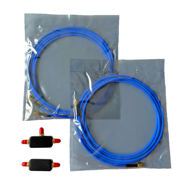
This portable passive HF/VHF loop antenna is designed for low NF receivers. It also works with RTL-SDR in direct sampling mode if you enable RTL AGC. Signals can be boosted by using any external low cost HF amplifier, or even our wideband LNA.
Specifications
HF Portable & Flexible Receive Loop Antenna
Covers HF frequencies (10 kHz to 30 MHz)
Usable on FM/VHF up to 300 MHz as a folded Dipole
Maximum power 250 mW
Passive Design
No Tuning required
Low-Loss Wide-Band BALUN with 0.28 dB loss typ
Connection: SMA Male on the end of the feedline
Included
1x YouLoop T shaped low-loss wide-band BALUN
1x Coax Inverter Connector
2x Semi-rigid RG402 coax with SMA Male connectors – Branches (1 m)
1x Semi-rigid RG402 coax with SMA Male connectors – Transmission (2 m)
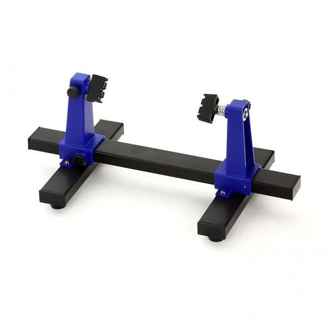
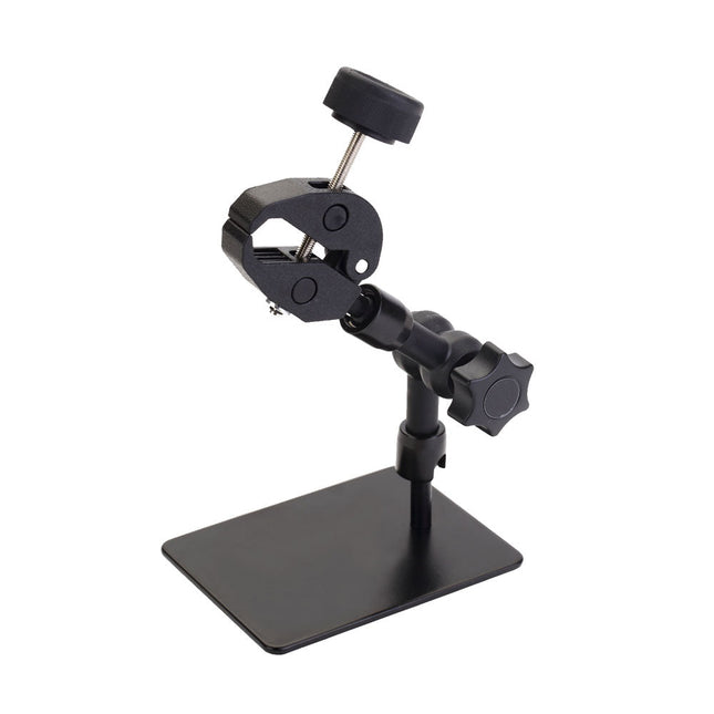
This adjustable circuit board holder is ideal for clamping PCB for soldering, desoldering or rework.
Features
2 adjustable grips on a retractable stand to accommodate various board sizes.
The adjustable clamps allow the PCB to rotate 360 degrees and stay set in any position.
The base of this rigid metal stand features four rubber feet to ensure stability.
Specifications
Product size
30 x 16.5 x 12.5 cm
Max. holding size
20 x 14 cm
Weight
450 g
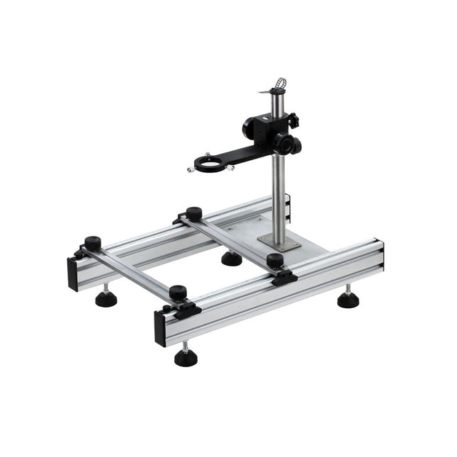
This multi-purpose tool offers an excellent all round solution, ideal for holding big size PCBs and desoldering work, etc.
Features
The arms of the repair station can move up and down conveniently, easy for operation.
The adjustable parts are made of the same material for microscope, with high quality, perfect stability and precision.
The rubber feet can move in all directions, ensuring the operation platform is always on a flat surface.
Suitable for desoldering BGA ICs.
Specifications
Rough adjusting range in height
0∼230 mm
Precise adjusting range in height
0∼60 mm
Max. holding size of PCB
250 mm (length or width)
Min. holding size of PCB
20 mm (length or width)
This PCB holder is ideal for any application where a third or fourth hand and a magnifying lamp are needed.
Features
The helping hands with 4 adjustable gooseneck arms.
LED magnifying lamp with USB-C interface.
Metal base with non-slip rubber strips.
Comes with a cleaning ball, a sponge, a solder wire stand and rosin.
Specifications
Length of gooseneck arms: 270 mm
LED magnifying lamp with 5-diopter lens
Power supply via USB
Dimensions (stand): 185 x 175 x 20 mm
Weight: 620 g
This desk lamp is ideal for your workplace. With the 5-inch 5D-lens, the finest work can be done. The lamp has 80 integrated LEDs.
Features
Lens size: 5 inch
Lens material: glass
Diopter: 5D
Light source: T5 22 W fluorescent energy-saving bulb (80pcs LED)
Standard mount: table base
Voltage: 220-240 V
Power: 22 W
Fumes released during the soldering process are potentially harmful to health. This solder fume extractor is securely fastened to the work table with a bracket. Thanks to the 3 axes, the solder fume extractor can be positioned perfectly, i.e. directly above the rising solder fumes. The harmful solder fumes are extracted by a powerful but quiet fan and filtered by an activated-carbon filter mat.
Features
Removes solder fumes
Absorbs toxic gases and fumes from brazing operations
Helps reduce the likelihood of headaches, eye irration and neusea
Adjustable absorption angle for accurate placement
Easy replaceable activated carbon filter
High-performance fan
Low noise and long life service
Specifications
Absorption capacity: 1 m³/min (max.)
Power consumption: 23 W
Power supply: 220-240 VAC
Amount of activated carbon filter: 7 g
Maximum absorption weight: 2 g
Dimensions: 220 x 270 x 168 mm (W x H x D)
Weight: 1.4 kg
This silicone soldering mat can be used as a base for all kinds of soldering work such as assembly or repair.
Specifications
Withstands 200-230°C constantly and 480-500°C for short periods
Ideal for soldering electronics components or repairing PCBs, smartphones, etc.
Color: Green
Dimensions: 209 x 295 mm
The ZD-5L Hot Glue Gun is a versatile and easy-to-use tool designed for household, DIY, and professional use. It features a compact and lightweight design for comfortable handling, and its built-in stand ensures safe and stable operation.
Whether you're a DIY enthusiast or a professional, this Glue Gun is a perfect addition to your toolkit, an efficient and practical solution for bonding, repairing, and creating. It is ideal for various materials like glass, cardboard, metal, plastic, leather, fabric and more.
The ZD-5L uses 7.2 mm glue sticks. It is powered by an 18650 battery and charged via USB-C.
Specifications
Charging Voltage
5 V DC
Charging Current
Adaptive, 2 A (max)
Charging Interface
USB-C
Battery
18650 Lithium
Glue Stick
7.2 mm OD
Heat-up time
approx. 2 min.
Time of Use
approx. 60 min.
Sleep Time
5 min. without action
Included
1x ZD-5L Glue Gun
1x 18650 Lithium battery (2200 mAh)
2x Glue Sticks (10 cm)
1x USB cable
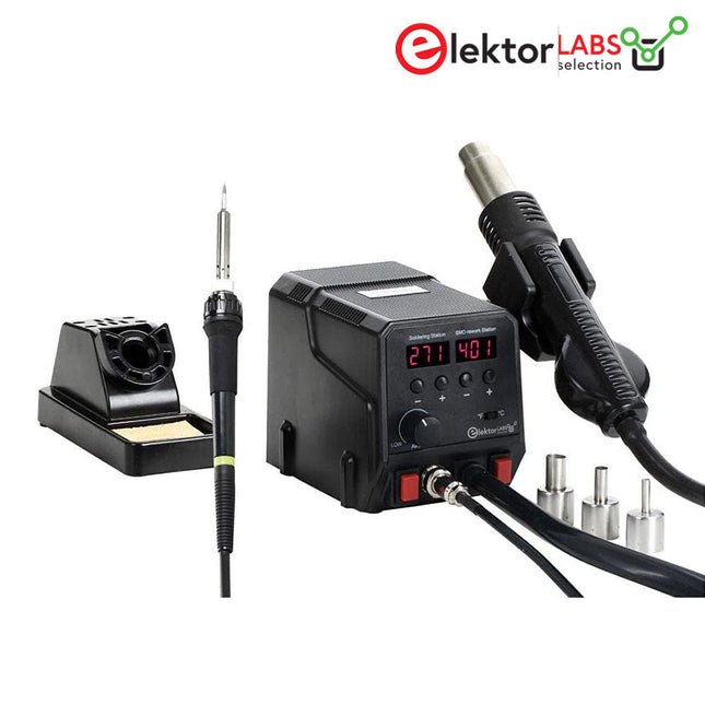
This 2-in-1 hot air soldering station offers a cost-effective solution for soldering and desoldering all types of SMD components.
Features
Incl. soldering iron and hot air pump. It is suitable for soldering and desoldering all types of surface mounted IC, PCB or components.
The control unit has 2 LEDs that display the temperature and in °C and °F. The temperature can be easily adjusted with simple up/down buttoms.
The hot air temperature can be calibrated from 3L/min to 24L/min continuously.
Temperature is micro-processor controlled and can be adjusted.
Temperature range: 50-480°C for soldering iron, 100-500°C for hot air pump.
Specifications
Power
Soldering iron: 24 V, 60 WHot air pump: 300 W
Power supply
220-240 V AC/50 Hz
Temperature range
Soldering iron: 50-480°CHot air pump: 100-500°C
Dimensions
113 x 125 x 175 mm
Weight
2 kg
Included
1x ZD-8922 Rework station
1x Soldering iron
1x Hot air gun
3x Hot air nozzles
1x Soldering iron with needle bit
1x Power cord
1x Soldering iron stand with sponge
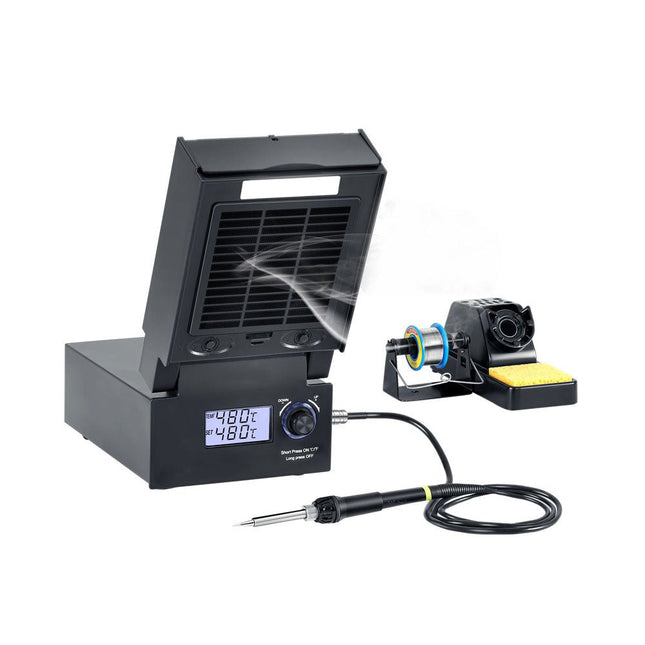
The ZD-8951 is a 3-in-1 temperature-controlled digital soldering station with built-in fume extractor and LED lighting. The rapid-heating function reaches a temperature of 400°C in less than 1 minute.
Specifications (Soldering Iron)
Power: 60 W (max. 130 W)
Temperature range: 160°C to 480°C (320°F to 896°F)
PTC rapid heating element
With °C/°F conversion function
Temperature can be easily adjusted with the knob.
LCD display with changing backlight.
With rapid heating function, it takes less than 1 minute to rise from the room temperature to 400°C (752°F).
Specifications (Fume Extractor)
Power: 23 W
Air flow: 1 m³/min (max)
Specifications (LED Light)
Power: 5 W
Lighting: 12 LEDs
Brightness: 242 lm
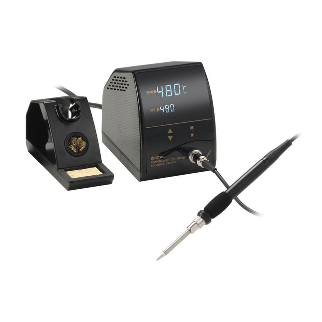
This temperature-controlled digital soldering station with adjustable temperature range from 160°C to 480°C is an affordable and reliable tool for all kinds of soldering work in the (home) laboratory. Thanks to the high-quality coated heating element, the desired soldering temperature (Celsius or Fahrenheit) is quickly reached and shown on the LED display.
Features
A temperature controlled soldering station with adjustable temperature range from 160°C to 480°C (320°F to 896°F).
A two-line LED readout simultaneously displays temperature setting and actual temperature.
Gloss finish pleasing to the eye.
Compact and lightweight soldering iron with silicone cord.
A user-friendly soldering iron handle with a foam sleeve.
Easier way to achieve °C/°F conversion with the asterisk button.
Specifications
Power
25 W (max. 50 W)
Display
LED
Temperature
160°C to 480°C (320°F to 896°F)
Temperature deviation
±5%
Grounded
Yes
Heating rate
Melt solder within 20s
Withstand voltage
1500/1MA
Input voltage
AC 220-240 V (50 Hz)
Output voltage
24 V
Included
ZD-8961-A Soldering station
Solderin iron stand
Soldering iron with soldering tip N8-1
Cleaning sponge
Cleaning ball
Power cord (EU)
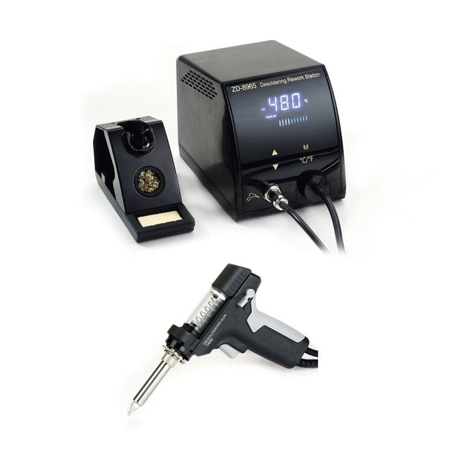
The ZD-8965 is a digital temperature-controlled desoldering station equipped with ground protection and an LCD screen for temperature display. Despite its compact and robust design, this high-power desoldering station is easy to operate with just one hand.
The ZD-8965 features a soldering gun with an integrated filter that captures any extracted material, allowing for continuous operation by simply replacing the filters. Additionally, a temperature sensor is embedded in the tip, enabling rapid response to temperature fluctuations for consistent performance.
Features
Effortlessly adjust the temperature between 160°C and 480°C using the convenient up/down buttons on the front panel.
LED display to indicate the temperature in °C/°F
Features an ergonomic pistol grip with a trigger for quick and efficient solder waste removal.
The upgraded soldering gun includes a rear trigger, making it exceptionally convenient for replacing and cleaning components.
Comes with a high-quality soldering gun and a sturdy holder.
Equipped with a heavy-duty heater that ensures optimal desoldering performance every time.
Specifications
Station
Voltage supply
220-240 V
Power
140 W
Vakuum pressure
600 mm HG
Desoldering Gun
Power
140 W (18 V DC)Heat up rating: 140 W
Temperature
160-480°C (320-896°F)
Heating element
Ceramic heater
Included
1x ZD-8965 Desoldering station
2x Spare soldering tips
3x Cleaning needles for desoldering tips
3x Spare filter for desoldering gun
1x Spare filter for desoldering station
1x Manual
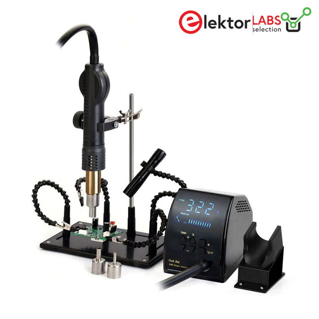
This Rework Station Bundle, consisting of the ZD-8968 Hot Air Rework Station and the ZD-11P PCB holder, offers precise temperature control, adjustable airflow, and a stable hold for your circuit board.
The ZD-8968 Hot Air Rework Station is a high-performance device designed for precision desoldering and rework tasks with SMD components. It features a wide temperature range of 100-500°C (212-932°F), with adjustable air and temperature control, a clear LED display, and an automatic sleep mode for enhanced safety and efficiency.
The ZD-11P PCB Holder is equipped with 5 adjustable 360° rotatable goosenecks (4 with alligator clips, 1 with flashlight holder + flashlight), providing additional flexibility and stability. It securely holds the PCB in place, making the handling of SMD components easier and more precise.
Features
300 W heating power ensures quick heat-up
Wide temperature range 100-500°C (212-932°F) allows precise control
Closed-loop sensor and MCU zero-crossing design ensure accurate and stable temperature regulation.
The hot air pump handle includes a built-in sensor that switches to Working Mode when picked up and to Standby Mode when placed back in the holder.
Automatic standby mode activates after 10 minutes of inactivity.
Automatic cooling system and deferred power-off function protect the heating element.
Brushless motor fan provides quiet operation, smooth airflow, and an extended lifespan.
High-quality heating element doubles working efficiency and saves energy.
LED digital display for clear monitoring of temperature settings.
Simple buttons for adjusting air volume and temperature.
Switching between °C and °F
Heat-resistant stand with hot air gun holder, 5 flexible adjustable arms with alligator clips and a flashlight (AA battery not included)
Specifications
ZD-8968 Hot Air Rework Station
Power
300 W
Temperature range
100-500°C (212-932°F)
Power supply
220-240 V AC/50 Hz
Weight
1.2 kg
ZD-11P PCB Holder
Base (Dimensions)
210 x 134 mm
Metal rod (Height)
250 mm
Included
Base, metal rod, 4 gooseneck arms with alligator clips, 1 gooseneck arm with flashlight holder
Included
1x ZD-8968 Hot Air Rework Station
1x ZD-11P PCB Holder (stand with soldering iron holder with 5 adjustable arms, 4 with alligator clips and 1 with flashlight holder)
1x Flashlight (AA battery not included)
3x Hot air nozzles (79-7911, 79-7912, 79-7913)
1x Power cord (EU)
1x Power cord (UK)
1x Manual
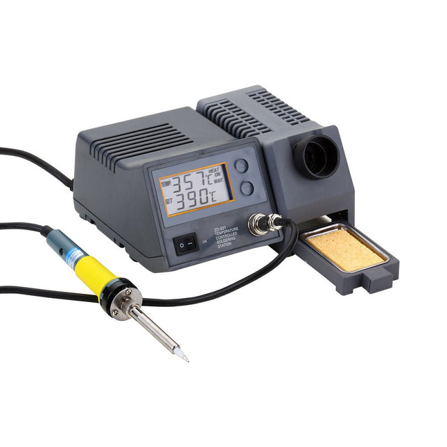
The powerful soldering station with LCD panel has been designed for a wide temperature range (from 150-450°C) and is ideal for general purpose soldering as well as specialized lead-free soldering applications. The soldering iron is controlled automatically by the microprocessor.
With its high-quality sensor the heat exchange system guarantees precise temperature control at the soldering tip. This digital temperature controlled soldering station includes a holder and cleaning sponge.
Specificaties
Operating voltage
220-240 V, 50 Hz
Power consumption
80 W
Soldering iron power
48 W
Operating voltage soldering iron
24 V
Temperature (adjustable)
150-450°C
Dimensions
195 x 87 x 165 mm