Trade products
-

Siglent Siglent SDS1104X-U 4-ch Oscilloscope (100 MHz)
The SDS1000X-U series employs SPO (Super Phosphor Oscilloscope) technology that provides excellent signal fidelity and performance. It comes with an innovative digital trigger system with high sensitivity and low jitter, and a waveform capture rate of 400,000 frames/sec (sequence mode). The SDS1000X U also employs a 256 level intensity grading display function and a color temperature display mode not found in other models in this class. Another powerful addition is the new 128 k point FFT math function that gives the SDS1000X-U a very high-frequency resolution when observing signal spectra. SDS1000X-U also supports searching and navigating. The features and performance of SIGLENT’s new SDS1000X-U cannot be matched anywhere else in this price class. Features 100 MHz bandwidth Real-time sampling rate up to 1 GSa/s The newest generation of SPO technology Waveform capture rates up to 100,000 wfm/s (normal mode) and 400,000 wfm/s (sequence mode) Supports 256-level intensity grading and color temperature display modes Record length up to 14 Mpts Digital trigger system Intelligent trigger: Edge, Slope, Pulse Width, Window, Runt, Interval, Time out (Dropout), Pattern Serial bus triggering and decoding (Standard), supports protocols I²C, SPI, UART, CAN, LIN Video trigger, supports HDTV 10 types of one-button shortcuts, supports Auto Setup, Default, Cursors, Measure, Roll, History, Display/Persist, Clear Sweep, Zoom and Print Segmented acquisition (Sequence) mode, divides the maximum record length into multiple segments (up to 80,000), according to trigger conditions set by the user Automatic measurement function for 38 parameters as well as Measurement Statistics, Zoom, Gating, Math, History and Reference functions History waveform record (History) function (maximum recorded waveform length is 80,000 frames) 128 k pts FFT, supports Peaks and Markers Math functions (FFT, addition, subtraction, multiplication, division, integration, differential, square root) Large 7 inch TFT LCD display with 800 x 480 resolution Downloads Datasheet Manual Programming Guide
€ 401,00
-
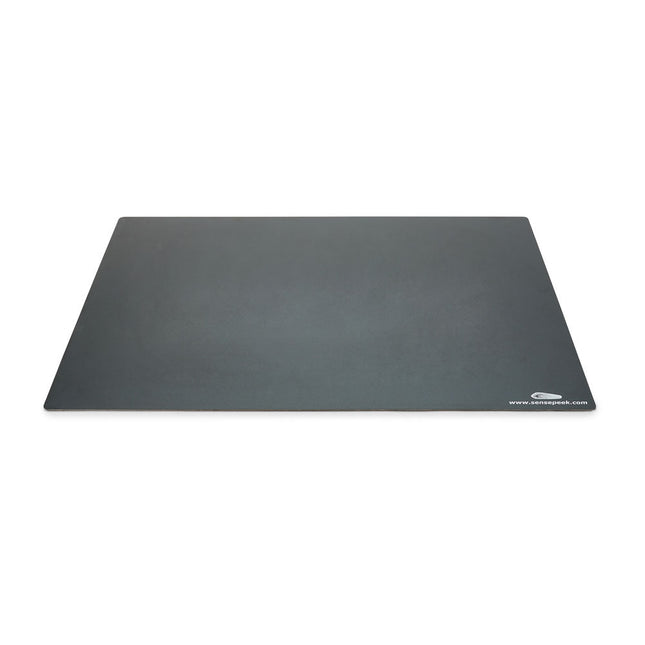
Sensepeek Sensepeek 4021 Insulated XL Base Plate
Components are both shrinking and getting increasingly finer pitch year after year but your PCBs might have grown in size or the number of interconnected PCBs or the number of handsfree PCBite probes needed to test your design may have increased making it crowded on our other smaller base plates. Features With a size of 297 x 420 mm (DIN A3) the extra large baseplate has room for most PCBs and many handsfree PCBite probes for those measurements sessions where more channels than available is needed. So if you are looking for more space, extra protection or just want to clean up your work surface then this accessory is a perfect match. Designed to be used with Sensepeeks magnetic PCBite line of products including PCB holders, hands free probes and magnifier. Included 1x XL base plate (DIN A3) with pre-fitted insulation cover
€ 71,39
-
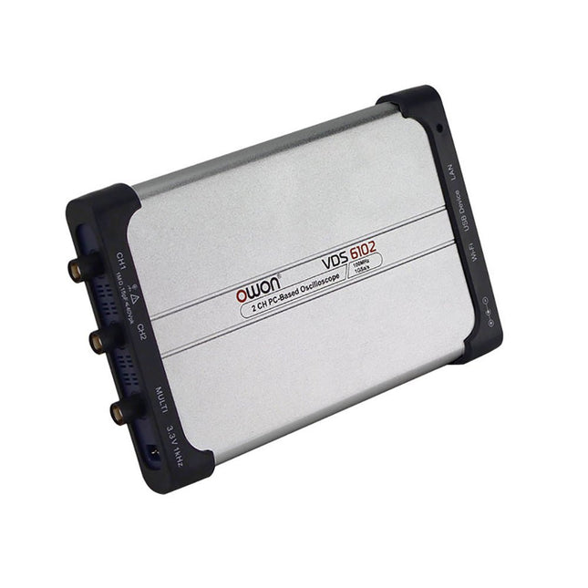
OWON OWON VDS6102A 2-ch USB Oscilloscope (100 MHz)
The OWON VDS6000 Series PC Oscilloscope combines powerful performance with a sleek, ultra-thin design. With 100 MHz bandwidth, 1 GSa/s real-time sampling, and up to 14-bit resolution, it delivers highly accurate measurements. The built-in 5 MHz function generator, USB-C power supply, and optional WiFi connectivity make it incredibly versatile. Compatible with Windows, Linux, Android, and iOS, the VDS6000 is perfect for labs, fieldwork, and remote diagnostics – compact, flexible, and ready for any challenge. Features Bandwidth: 100 MHz Vertical resolution: 14 bits Rise time: ≤3.5 ns Memory: 10 Mpts Number of channels: 2 channels + 1 channel function generator Horizontal scale: 5ns - 100s/div Sample rate: Max. 1 GSa/s Maximum voltage: 40 V (peak - peak) Automatic measurements: Vpp, Vavg, Vamp, Vrms, Freq, Period, Vmax, Vmin, Vtop, Vbase, Overshoot, Preshoot, Rise Time, Connectivity: USB-C, LAN, Wifi (optional) Fall Time, Delay A→B↑, Delay A→B↓, +Width, -Width, +Duty, -Duty Bandwidth: 5 MHz Sample rate: 25 MSa/s Standard waveforms: Sine (0.1 Hz - 5 MHz), Square (0.1 Hz - 200 kHz), Ramp (1 Hz - 10 kHz), Pulse (1 Hz - 10 kHz) Resolution: 10 bits DC offset range (AC + DC): ±2.5 V Amplitude range: 10 mVpp - 5 Vpp Dimensions: 190 x 120 x 18 mm Weight: 380 g Downloads Manual Quick Guide PC Software MacOS Software
€ 330,00
-
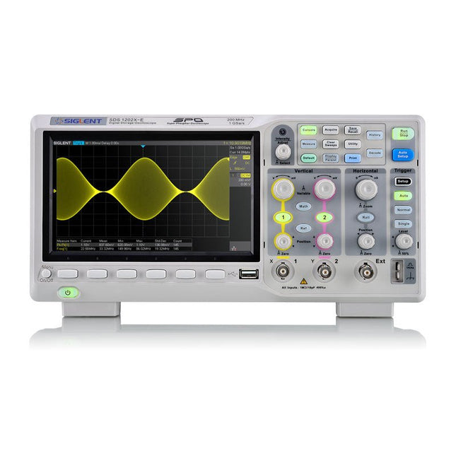
Siglent Siglent SDS1202X-E 2-ch Oscilloscope (200 MHz)
SIGLENT’s SDS1000X-E Series Super Phosphor Oscilloscope is available in one bandwidth, 200 MHz. It has a maximum sample rate of 1 GSa/s and a standard record length of 1 Mpts. For ease-of-use, the most commonly used functions can be accessed with its user-friendly front panel design. The SDS1000X-E series employs a new generation of SPO (Super Phosphor Oscilloscope) technology that provides excellent signal fidelity and performance. The system noise is also lower than similar products in the industry. It comes with a minimum vertical input range of 500 uV/div, an innovative digital trigger system with high sensitivity and low jitter, and a waveform capture rate of 400,000 frames/ sec (sequence mode). The SDS1000X-E also employs a 256-level intensity grading display function and a color temperature display mode not found in other models in this class. Siglent’s latest oscilloscopes offering supportsmultiple powerful triggering modes including serial bus triggering. Decoding is standard configuration including IIC,SPI,UART,CAN,LIN. History waveform recording and sequential triggering enable extended waveform recording and analysis. Another powerful addition is the new 1 million points FFT math function that gives the SDS1000X-E very high frequency resolution when observing signal spectra. The new design also includes a hardware co-processor that delivers measurements quickly and accurately. The features and performance of Siglent’s new SDS1000X-E cannot be matched anywhere else in this price class. Specifications Bandwidth 200 MHz Channels 2CH+1EXT Real time sampling rate 1 GSa/s Memory depth 7 Mpts/CH (Dual-Channel); 14 Mpts/CH (Single-Channel) Waveform Capture Rate (Max.) 100,000 wfm/s (normal mode); 400,000 wfm/s (sequence mode) Serial Trigger (Standard) I²C, SPI, UART/RS232, CAN, LIN Decode Type (Standard) I²C, SPI, UART/RS232, CAN, LIN Trigger Type Edge, Slope, Pulse Width, Window, Runt, Interval, Dropout, Pattern, Video Probe (Std) 2 pcs passive probe PP215 Display 7 inch TFT-LCD (800x480) Weight Without package 2.5 kg; with package 3.5 kg Downloads Datasheet Manual Programming Guide
€ 401,99
-

Siglent Siglent SPD3303X-E 3-ch DC Power Supply (220 W)
SPD3000X Series Linear Programmable DC Power Supply has a 4.3-inches TFT LCD display, Supports Programmability and Real Time Wave Display, bringing a new experience to users. It has three isolated outputs: two adjustable channels and one selectable channel from 2.5V, 3.3V, and 5V. It also has output short and overload protect function, and can be used in production and development. Features 3 independent controlled and isolated output, 32V/3.2A×2, 2.5V/3.3V/5V/3.2A×1, total 220W. 5 digits Voltage, 4digits Current Display, Minimum Resolution: 10mV/10mA. Supports panel timing output functions. 4.3 inch true color TFT LCD 480x272 pixel display. 3 kinds of output modes: independent, series, parallel. 100V/120V/220V/230V compatible design to meet the needs of different power grids. Intelligent temperature-controlled fan, effectively reducing noise. Clear graphical interface, with the waveform display function Internal 5 groups of system parameter save/recall, supports data storage space expansion. Provides PC software: Easypower, supports SCPI, LabVIEW driver. High-resolution and high-precision output The highest resolution of 10mV/10mA, provides excellent setting and read back accuracy. This ensures accurate output even with very with small changes in voltage or current. This is impossible for a low resolution power supply. Series/parallel/independent mode function Series and parallel function allows two channels combined into one output with more power output capability, extending the application range. Each of 3 channels power can be turned on or off independently and also can be turned all on or all off. Panel displays the timing output Through the panel operation, 5 groups of timing settings and output control can be displayed, which provides users a simple power programming function. Also a connection can be made with Siglent’s EasyPower PC software providing a full range of communication and control requirements. Save/Recall setting parameters SPD3000X series programmable power supply can save or recall 5 groups of setting parameter in internal storage, also supports external storage expansion. You can easily obtain the settings you needed.
€ 436,51
-

iFixit iFixit iOpener Toolkit
Electronic devices increasingly come with glued displays and batteries. And while the adhesive seal serves as a protection against dirt and water, it complicates the opening procedure of the device and hence its repair. The iOpener: Warm it through, unstick the glue! With the help of our iOpener, you can easily and quickly loosen adhesive without risking damage to your device due to overheating with a heat gun. Originally designed for opening Apple iPads, the iOpener is just as suitable for Samsung tablets, Sony smartphones, and devices from any other manufacturer who prefers adhesive over screws. How it works Heat the iOpener and place it on your device: Simply heat up the iOpener in the microwave or a pot of boiling water and position it on the edge of your device. The heat will soften the adhesive without damaging your gadget so you can insert an opening pick between the display and the case. Repeat this procedure for all glued areas, the iOpener is reusable any number of times. Use opening tools to remove adhesive residue: With the right tools, you’re now ready to open your device without hassle. The opening picks are sharp-edged enough to cut through the adhesive strips. Complete the opening procedure by prying up the case with an opening tool or lift your display with a suction cup or an iSclack. A must-have for electronic repairs The most annoying part of your repair is done, the rest will be almost a cinch. Whether you are a beginner or a professional, the iOpener should be part and parcel of every toolbox worthy of its name. Your advantages Loosen adhesive fastenings Uncomplicated to heat up in the microwave or boiling water Reusable Optionally available with opening tools Contains food grade glycerine Saves money and the planet Included iOpener Spudger iFixit Opening Tool 6x iFixit Opening Picks iFixit Battery Isolation Pick Plastic Cards Suction Cup Angled Tweezers Plastic bit driver with magnetic bit socket (4 mm), rubberized handle and swivel cap Precision bits (4 mm) Phillips #00 Flathead 2.5 mm
€ 24,95
-

Raspberry Pi Foundation Get Started with MicroPython on Raspberry Pi Pico (2nd Edition)
Fully updated for Raspberry Pi Pico W, this book gets you started with Raspberry Pi Pico – whether you’re using Raspberry Pi Pico for a home project, industrial automation, or learning (or teaching!) electronics and programming. Microcontrollers, like the RP2040 chip at the heart of Raspberry Pi Pico, are computers stripped back to their bare essentials. You don’t use monitors or keyboards with them – instead, you program them over USB to take their input from (and send their output to) on-board input/output pins. Using these programmable connections, you can light LEDs, make noises, send text to screens, and much more. In this book, you will learn how to use the beginner-friendly MicroPython language to write programs, and you’ll connect up hardware to make your Raspberry Pi Pico interact with the world around it. Using these skills, you can create your own electromechanical projects, whether for fun or to make your life easier. Fully updated for Raspberry Pi Pico W and the latest version of MicroPython, this book shows you how to: Get started with Raspberry Pi Pico and Pico W Work with various electronic components Create your own programmable electronic contraptions Turn Raspberry Pi Pico W into a network-connected node for the Internet of Things Link your Pico W to your smartphone, tablet, or another Pico W with Bluetooth Low Energy (BLE) Whether you’re using Raspberry Pi Pico for a home project, industrial automation, or learning (or teaching!) electronics and programming, this book will show you how.
-
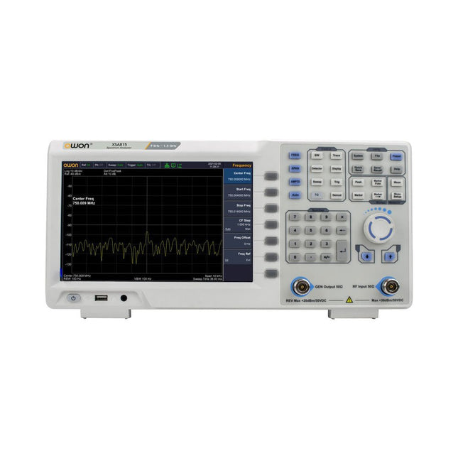
OWON OWON XSA815-TG Spectrum Analyzer (9 kHz – 1.5 GHz)
The OWON XSA815-TG (9 kHz-1.5 GHz) is a cost effective spectrum analyzer with tracking generator included and a frequency resolutions of 1 Hz. Features Frequency Range from 9 kHz to 1.500009 GHz 9-inch display 9 kHz to 1 MHz -95 dBm Displayed Average Noise Level, 1 MHz to 500 MHz 140 dBm (Typical), <-130 dBm Phase Noise -10 kHz <-80 dBc/Hz 100 kHz <-100 dBc/Hz 1 MHz <-115 dBc/Hz Resolution Bandwidth (-3 dB): 1 Hz to 1 MHz, in 1-3-5-10 sequence Tracking Generator Kit: 100 kHz to 1.500009 GHz Specifications Frequency Range 9 kHz to 500.009 MHz Frequency Resolution 1 Hz Frequency Span 9 kHz to 1.500009 GHz Span Range 0 Hz, 100 Hz to max frequency of instrument Span Uncertainty ±span / (sweep points-1) SSB Phase Noise (20°C to 30°C, fc=1 GHz) Carrier Offset 10 kHz <-80 dBc/Hz | 100 kHz <-100 dBc/Hz | 1 MHz <-115 dBc/Hz Resolution Bandwidth (-3 dB) 1 Hz to 1 MHz, in 1-3-5-10 sequence RBW Accuracy <5% typical Resolution Filter Shape Factor (60 dB: 3 dB) <5 typical Video Bandwidth (-3 dB) 10 Hz to 1 MHz, in 1-3-5-10 sequence Amplitude measurement range DANL to +10 dBm, 100 kHz to 10 MHz, Preamp Off DANL to +20 dBm, 10 MHz to 1.5 GHz, Preamp Off Reference Level -80 dBm to +30 dBm, 0.01dB by step Preamp 20 dB, nominal, 100 kHz to 1.5 GHz Input Attenuator 0 to 40 dB, 1 dB by step Display Average Noise Level Input attenuation = 0 dB, RBW = VBW = 100 Hz, sample detector, trace average ≥ 50, 20°C to 30°C, input impedance = 50 Ω) Preamp Off 9 kHz to 1 MHz -95 dBm (Typical), <-88 dBm Preamp Off 1 MHz to 500 MHz -140 dBm (Typical), <-130 dBm Preamp On 100 kHz to 1 MHz -135 dBm (Typical), <-128 dBm Preamp On 1 MHz to 500 MHz -160 dBm (Typical),<-150 dBm Tracking Generator (optional) Frequency Range 100 kHz to 1.500009 GHz Output power level range -40 dBm to 0 dBm Output level resolution 1 dB Output flatness Relative to 50 MHz | ±3 dB Tracking generator spurious Harmonic spurious -30 dBc (Tracking generator output power -10 dBm) Non-harmonic spurious -40 dBc (Tracking generator output power -10 dBm) Tracking generator to input terminal isolation -60 dB (Tracking generator output power 0 dBm) Tracking generator to input terminal isolation -60 dB (Tracking generator output power 0 dBm) Tracking generator to input terminal isolation -60 dB (Tracking generator output power 0 dBm) Dimensions 375 x 185 x 120 mm Weight 3.7 kg Included 1x XSA815-TG 1x 220 V AC power cord 1x USB Cable 1x Quickstart guide Downloads Quick Guide Specifications
€ 907,50
-

Electron Plus Electron Plus SPA100 Source Picoammeter
This highly sensitive source picoammeter is designed for measuring and logging very small currents down to the pA range – making it an ideal instrument for scientific and research applications, including physics, materials science and electron microscopy. Full-featured at an affordable price, the SPA100 combines sensitivity, accuracy and stability to allow users to measure low currents with high precision as well as conveniently source bias voltages for experimentation. SPA100 also doubles as an ultra-high resistance meter, measuring accurately into the teraohm range. The SPA100 connects to PC via USB and utilises the complimentary software SPA – enabling users to easily measure, graph and capture readings with timestamps and measurement stability information. Features Input: ±2 mA to ±200 pA in 8 ranges Accuracy and Resolution (2 Hz): ±2 mA range: ±0.1%, resolution <20 nA ±200 uA range: ±0.1%, resolution <2 nA ±20 uA range: ±0.2%, resolution <200 pA ±2 uA range: ±0.2%, resolution <20 pA ±200 nA range: ±0.5%, resolution <2 pA ±20 nA range: ±0.5%, resolution <200 fA ±2 nA range: ±1.0%, resolution <20 fA ±200 pA range: ±1.5%, resolution <2 fA Sample rate: 2 Hz (18 bit) or 10 Hz (16 bit) Adjustable filter: 1 sample to 64 samples Output voltage: -40 V to +40 V (in 1 V increments), output resistance 2.7 Kohms Resistance Measurement: ~1 Kohms to 40 Tohms (e.g 40 V source, 1 pA measure) Accuracy: >±0.5% 1 Mohm to 1 Tohm Powered via USB 2.0 (instrument uses up to 0.3 A when in-use) Included 1x SPA100 Source Picoammeter 1x USB cable Downloads Manual Software
€ 264,99
-

Velleman Whadda Electronic Dice
This electronic dice with 7 red LEDs rolls when the push button is released and works with a 9 V battery (not included). Downloads Manual
€ 6,50
-

Sensepeek Sensepeek 6024 SQ500 (500 MHz handsfree Oscilloscope Probe)
The SQ series of handsfree probes from Sensepeek have a lower point of gravity making them even more stable compared with the original SP series of handsfree probes. All probes in the SQ series are also insulated and can be used handheld as any traditional probe but their full potential is used when measuring handsfree. The SQ series of oscilloscope probes also includes more ground options, have probe tip protection, longer cable and support for oscilloscopes with automatic scaling (10:1). All the loved features of handsfree measurement, exchangeable fine pitch spring tipped test needle, color-coded cable holders and the minimalistic design is maintained to make traditional sized and handheld probes obsolete. Both length and weight of the SQ probes are perfectly balanced to be used with PCBite PCB holders and base plate which is a must for handsfree function. Features Passive 10:1 probe with support for oscilloscopes with automatic scaling Spring-loaded test needle for fine pitch measurements Multiple ground options Color coded cable holders Probe tip protection Insulated, can be used handheld Improved probe holder for handsfree measurement when used with PCBite PCB holders Included 1x SQ500 500 MHz probe with spring tipped test needle 1x SQ probe holder for handsfree measurement 1x Testhook with detachable cables (5 cm & 10 cm) for convenient ground connection 1x Alligator cable for convenient ground connection 1x Standard ground spring, for handheld measurements at rated bandwidth 1x Unique ground spring, for total handsfree measurements at rated bandwidth 1x Set of color coded cable holders (4 colors) 1x Probe tip protection 1x Extra test needle Downloads User Guide SQXX0 Rev1.1
€ 131,89
-

OWON OWON SPS6051 Fanless DC Power Supply (150 W)
The OWON SPS6051 Fanless Programmable DC Power Supply (150 W) delivers ultra-quiet, high-precision performance with 10 mV/1 mA accuracy and advanced heat dissipation for long-term reliability. Featuring comprehensive protection, a USB interface with SCPI support for remote control, and a 2.8-inch TFT LCD screen, it is the perfect choice for laboratories, electronics testing, and research. Features Fanless design: Ultra-quiet operation, reducing vibration noise and minimizing the potential failure risks associated with traditional cooling fans. Excellent heat dissipation design: Ensures a controlled temperature rise, allowing long-term operation under full load conditions and extending internal component longevity. Lightweight and ultra-thin design. Output accuracy up to 10 mV/1 mA. Supports List waveform editing and output, with four memory shortcut parameters for quick and convenient access. Integrated protection features include overvoltage, overcurrent, overtemperature, and input undervoltage protection for enhanced safety. Built-in discharge circuit prevents residual high voltage risks when the power is turned off. USB communication interface with SCPI protocol support, enabling PC programming and remote control for simplified user management. 2.8-inch TFT LCD screen Specifications Model SPS6051 SPS3081 Rated Output (0°C-40°C) Voltage 0-61 V 0-31 V Current 0-5.1 A 0-8.1 A Power 150 W 120 W Load Regulation Voltage ≤30 mV Current ≤20 mA Power Regulation Voltage ≤30 mV Current ≤20 mA Setting Resolution Voltage 10 mV Current 1 mA Readback Resolution Voltage 10 mV Current 1 mA Seting Accuracy (25°C ±5°C) Voltage ≤0.05% ±20 mV ≤0.1% ±20 mV Current ≤0.05% ±20 mA ≤0.2% ±20 mA Readback Accuracy (25°C ±5°C) Current ≤0.05% ±20 mV ≤0.1% ±20 mV Voltage ≤0.05% ±20 mV ≤0.2% ±20 mA Ripple/Noise Voltage ≤30 mVp-p ≤30 mVp-p Voltage ≤4 mVrms ≤5 mVrms Current ≤10 mAp-p ≤30 mAp-p Output temperature coefficient (0°C-40°C) Voltage 100 ppm/°C Current 200 ppm/°C Readback temperature coefficient Voltage 100 ppm/°C Current 200 ppm/°C Response Time (50-100% rated load) ≤1.0 ms Storage 4 groups of data Working Temperature 0-40°C Display 2.8-inch color LCD display Interface USB Dimensions (W x H x D) 82 x 142 x 226 mm Weight 1.8 kg Included 1x OWON SPS6051 Power Supply 2x Test leads 1x Power cord 1x Manual Downloads Datasheet User Manual Programming Manual PC Software
€ 134,31
-

OWON OWON DGE3062 2-ch Arbitrary Waveform Generator (60 MHz)
The OWON DGE3062 is a 14-bit function generator with a bandwidth of 60 MHz. It has 5 basic waveforms, 160 built-in arbitrary waveforms and the following comprehensive modulation functions: AM, FM, PM, PWM, FSK, 3FSK, 4FSK, PSK, ASK, BPSK, OSK, DSBAM, QPSK, SUM, sweep, Burst. Features Max. 60 MHz frequency output, 300 MSa/s Sample rate 14 bits Vertical Resolution, 100K Arb waveform length Comprehensive waveform output: 5 basic waveforms, and 160 built-in arbitrary waveforms Comprehensive modulation functions: AM, FM, PM, PWM, FSK, 3FSK, 4FSK, PSK, ASK, BPSK, OSK, DSBAM, QPSK, SUM, sweep, Burst SCPI and LabVIEW supported 3.6 inch LCD (480 x 272 pixels) Specifications Channel 2 Frequency Output 60 MHz Sample Rate 300 MSa/s Vertical Resolution 14 bits Waveform Standard Waveform Sine, square, pulse, ramp, noise Arbitrary Waveform Exponential rise, exponential fall, sin(x)/x, step wave, and others, total 160 built-in waveforms Frequency (resolution 1 μHz) Sine 1 μHz-60 MHz Square 1 μHz ~ 20 MHz Pulse 1 μHz ~ 20 MHz Ramp 1 μHz ~ 2 MHz Noise 20 MHz (-3 dB, typical) Arbitrary Waveform 1 μHz ~10 MHz Arbitrary Waveform Length 2 points – 100K points Sample Rate 300 MSa/s Amplitude Into 50Ω load 1mVpp ~ 10Vpp (≤10Hz), 1mVpp ~ 5Vpp (≤60 MHz) DC Offset Range (AD+DC ±(10 Vpk – Amplitude Vpp/2) high resistance±(5 Vpk – Amplitude Vpp/2) 50 Ω DC offset resolution 1 mV or 4 digits Load Impedance 50 Ω (typical) DC offset Accuracy ±(1% of |setting| + 1 mV + amplitude Vpp * 0.5%) Modulation Type AM,FM, PM, PWM, FSK, 3FSK, 4FSK, PSK, ASK, BPSK, OSK, DSB-AM, QPSK, SUM, Sweep, Burst Frequency Counter Function Frequency, period Frequency Range 100 MHz ~ 100 MHz Frequency Resolution 6 digits Input/Output Display 3.6” LCD Input mode External modulation input, external trigger input, external reference clock input/output Communication Interface USB Host, USB Device Mechanical specifications Dimensions (W x H x D) 200 x 92 x 157 mm Weight 0.8 kg Included 1x OWÒN DGE3062 Arbitrary Waveform Generator 1x Power Cord 1x Quick Guide 1x USB Cable 1x Q9 Cable 1x BNC to Alligator Clip Downloads Quick Guide Manual Software
€ 212,50
-

OWON OWON P4603 DC Power Supply (180 W)
This OWON DC Power Supply has a small body and is easy to carry due to its light weight. Featuring a 3.7" TFT LCD display, it has a maximum output power of 180 W and a resolution of 1 mV/1 mA. Features Channel Single Channel Output Total Output Power 180 W Channel Output 0 - 60 V / 0 - 3 A × 1-CH Display 3.7' color LCD display Dimension 117 mm(L) × 194 mm(H) × 295 mm(D) Weight Approx. 5.8 kg Interface RS232 Specifications Rated Output (0 ℃ - 40 ℃) Voltage 0 - 60 V Current 3 A Load Regulation Voltage ≤ 0.01% + 3 mV Current ≤ 0.01% + 3 mA Power Regulation Voltage ≤ 0.01% + 3 mV Current ≤ 0.01% + 3 mA Setting Resolution Voltage 1 mV Current 1 mA Readback Resolution Voltage 1 mV Current 1 mA Setpoint accuracy (within 12 months) (25 ℃ ± 5 ℃) Voltage ≤ 0.03% + 10 mV Current ≤ 0.1% + 5 mA Readback Resolution (25 ℃ ± 5 ℃) Voltage ≤ 0.03% + 10 mV Current ≤ 0.1% + 5 mA Ripple/Noise (20 Hz - 20 MHz) Voltage (Vp-p) ≤ 4 mVp-p Voltage (Vrms) ≤ 1 mVrms Current (rms) ≤ 4 mArms Output temperature coefficient(0 ℃ - 40 ℃) Voltage ≤ 0.03% + 10 mV Current ≤ 0.1% + 5 mA Readback temperature coefficient Voltage ≤ 0.03% + 10 mV Current ≤ 0.1% + 5 mA Response Time 100 μs Storage 5 groups of data Working Temperature 0 - 40 ℃
€ 164,57
-

OWON OWON SDS1104 4-ch Oscilloscope (100 MHz)
Specifications Bandwidth 100 MHz Sample Rate 100 MS/s Horizontal Scale (s/div) 5ns/div - 1000s/div, step by 1 - 2 - 5 Channel 4 Display 7" color LCD, 800 x 480 pixels Input Coupling DC, AC and GND Vertical Resolution (A/D) Vertical Resolution (A/D) Vertical Sensitivity 5mV/div - 5V/div (at input) Trigger Type Edge, Video Trigger Mode Auto, Normal and Single Waveform Math +, -, x, ÷, invert, FFT Fuse 2A, T class, 250 V Dimension (W x H x D) 301 x 152 x 70 mm Weight 1.1 kg Included 1 x SDS1104 1 x Mains power cord 1 x CD Rom 1 x Quickstart Guide 1 x USB Cable 4 x Oscilloscope probe 1 x Probe Adjust For more information, check out the user manual here.
€ 249,00
-

Weller Weller WE1010 Digital Soldering Station (70 W)
High-quality soldering station with the most important tools and consumables, ideal for universal soldering applications. Features 1-Channel Power Unit, digital, 70 W Power unit, 1 channel with soldering iron WEP 70 and safety rest PH 70 70W solder iron with ergonomic handle and providing toolless tip change ESD safe station, iron and heat-resistant silicon cable for safe handling Using ET soldering tips Standby mode and auto setback conserves energy, protects equipment Password-protected to preserve settings Specifications Dimensions: 150 x 120 x 98 mm Weight: 1.4 kg Display: Digital LC Display Temperature range: Adjustable from 100°C - 450°C (200°F - 850°F) Voltage: 230 V Channels: 1 Temperature range (depends on tool) °C: 100-450 Temperature range (depends on tool) °F: 200-850 Temperature accuracy °C: Average tip temperature can be „offset“ to +/- 5°C at idle with no load Temperature accuracy °F: Average tip temperature can be „offset“ to +/- 9°F at idle with no load Temperature stability °C: ±6 Temperature stability °F: ±10 Heat-up time (ca) in seconds (50-350°C / 120-660°F): 28 sec. Heating output: 85 W
€ 157,60
-
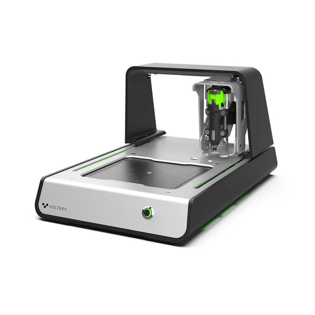
Voltera Voltera V-One Desktop PCB Printer
Solder Paste Dispensing and Reflow All-in-One The Voltera V-One creates two-layer prototype circuit boards on your desk. Gerber files go in, printed circuit boards come out. The dispenser lays down a silver-based conductive ink to print your circuit right before your eyes. Assembling traditional and additive boards is easy with the V-One’s solder paste dispensing and reflow features. Simply mount your board on the print bed and import your Gerber file into Voltera’s software. No more stencils required Voltera’s software is designed to be understood easily. From importing your Gerber files to the moment you press print, the software safely walks you through each step. Compatible with EAGLE, Altium, KiCad, Mentor Graphics, Cadence, DipTrace, Upverter. Included V-One PCB printer V-One dispenser V-One probe Nozzle pack Tip caps 3 x 4" FR1 substrate pack 2 x 3" FR1 substrate pack Substrate clamps Thumbscrew pack Hello World kit Solder wire Tweezers Power supply Power adapter Cables User guides Downloads Specifications V-One Software Manuals Safety Datasheets Technical Datasheets Voltera CAM file for EAGLE Substrates and Templates More Info Frequently Asked Questions More from the Voltera community Technical Specifications Printing Specifications Minimum trace width 0.2 mm Minimum passive size 1005 Minimum pin-to-pin pitch (conductive ink) 0.8 mml Minimum pin-to-pin pitch (solder paste) 0.5 mml Resistivity 12 mΩ/sq @ 70 um height Substrate material FR4 Maximum board thickness 3 mm Soldering Specifications Solder paste alloy Sn42/Bi57.6/Ag0.4 Solder wire alloy SnBiAg1 Soldering iron temperature 180-210°C Print Bed Print area 135 x 113.5 mm Max. heated bed temperature 240°C Heated bed ramp rate ~2°C/s Footprint Dimensions 390 x 257 x 207 mm (L x W x H) Weight 7 kg Computing Requirements Compatible operating systems Windows 7 or higher, MacOS 10.11 or higher Compatible file format Gerber Connection type Wired USB Certification EN 61326-1:2013 EMC requirements IEC 61010-1 Safety requirements CE Marking Affixed to the Voltera V-One printers delivered to European customers Designed and assembled in Canada. More technical information Quickstart Explore Flexible Printed Electronics on the V-One Voltera V-One Capabilities Reel Voltera V-One PCB Printer Walkthrough Unpacking the V-One V-One: Solder Paste Dispensing and Reflow All-in-One Voltera @ Stanford University's Bao Research Group: Robotic Skin and Stretchable Sensors Voltera @ Princeton: The Future of Aerospace Innovation
-

JOY-iT JOY-iT PS1440-C-Pro Programmable Laboratory Power Supply with RS485 (1440 W)
With the JOY-iT PS1440-C-Pro, you get a programmable laboratory power supply that delivers DC voltages ranging from 0.01 to 60 V and DC currents from 0.01 to 24 A at the voltage output. The intuitive control panel allows you to program, store, and recall up to 9 different DC voltage settings. You can also configure individual protection and limiting functions—such as overvoltage protection. All settings are easily adjusted via the keypad and/or rotary control and are clearly shown on the high-resolution 2.4" color display. For enhanced connectivity, the PS1440-C-Pro includes an RS485 interface for robust, long-distance communication. This makes it ideal for complex setups where signal stability, noise immunity, and reliable data transfer are critical. The included connector ensures a secure connection, improving the overall reliability and performance of your laboratory equipment setup. Features Complete device ready for immediate use RS485 interface Battery charging function Values can be entered conveniently via keypad Over current & over voltage protection adjustable Integrated RTC, NTC temperature sensor Included detailed documentation in English, German & French Specifications Input voltage 230 V Output voltage 060 V Output current 0-24 A Output power 0-1440 W Input voltage accuracy ±1% +5 digits Output voltage accuracy ±0.3% +3 digits Output current accuracy ±0.5% +5 digits Battery voltage ±0.5% +3 digits Input voltage measurement resolution 0.01 V Output voltage measurement resolution 0.01 V Current measurement resolution 0.01 V Battery voltage measurement resolution 0.01 V Response time in constant voltage mode 2 ms @ 0.1-5 A Load regulation in constant voltage mode ±0.1% +2 digits Load regulation in constant current mode ±0.1% +3 digits Measuring range electric charge 0-9999.99 Ah Measuring range energy 0-9999.99 Wh Statistical errors in electric charge & energy ±2% Output ripple 100 mV VPP @ 12 V150 mV VPP @ 24 V Sensor temperature detection range −10~100°C (0-200°F) Sensor temperature detection accuracy ±3°C (±6°F) Working mode Step-down operation Screen brightness setting Level 0-5, 6 levels in total Permissible working temperature −10~40°C (0-104°F) Dimensions 170 x 93 x 340 mm Included JOY-iT PS1440-C Power Supply 2-pin connector for RS485 interface Power cord Manual Downloads Datasheet MODBUS Protocol PC Software Driver for Windows
€ 499,00
Members: € 449,10
-

iFixit iFixit Magnetic Project Mat
The 8x10" iFixit Magnetic Project Mat catches and securely holds screws as you pull them out of a device. Now you can stop worrying about keeping track of all the loose screws and focus on your repair. Screws and small parts will remain right where you left them. For laptops with hundreds of screws, use the whole mat as a screw guide and keep careful location notes. Included is a pen – made by Staedtler, producer of top-of-the-line pens and pencils for artists and architects – that was specially designed for the Project Mat. The Lumocolor Correctable pen resists smears and won't wipe away with a casual brush of your hand. When your repair is complete, use the eraser tip or a dry cloth to wipe the ink away clean. Features Organize all your small parts while you work on a device. The dry-erase surface lets you keep notes and location sketches. Reduces reassembly time by up to 40% while preventing errors.
€ 19,95
-
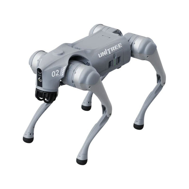
Unitree Unitree Go2 Pro Quadruped Robot
Temporary Delay in the Delivery of Unitree Robots Like many other suppliers, we are currently experiencing delays in the delivery of Unitree robots. A shipment from our supplier is currently held in customs, which has unfortunately led to later-than-planned deliveries for previously placed orders. We are actively working with our supplier to resolve this issue and expect more clarity soon, but at this time, we cannot provide any guarantees. Additionally, a new shipment is already on its way, though it will take some time to arrive. Since other suppliers are facing similar challenges, switching to a different provider is unlikely to result in a faster solution. Our top priority remains fulfilling existing orders. If you have any questions or would like to update your order, please do not hesitate to contact our customer service team. We will keep you informed of any further developments. Unitree Go2 series consists of quadruped robots for the research & development of autonomous systems in the fields of human-robot interaction (HRI), SLAM & transportation. Due to the four legs, as well as the 12DOF, this robot can handle a variety of different terrains. The Go2 comes with a perfected drive & power management system, which enables a speed (depending on the version) of up to 3.7 m/s or 11.88 km/h with an operating time of up to 4 hours. Furthermore, the motors have a torque of 45 N.m at the body/thighs and at the knees, which also allow jumps or backflips. Features Super Recognition System: 4D LIDAR L1 Max Running Speed: approx. 5 m/s Peak Joint Torque: approx. 45 N.m Wireless Module: WiFi 6/Bluetooth/4G Ultra-long battery Endurance: approx. 2-4 h (long battery life measured in real life) Intelligent Side-follow System: ISS 2.0 Specifications Tracking module: Remote-controlled or automatic tracking Front camera: Image tansmission Resolution 1280x720, FOV 120°, Ultra wide angle lens deliver rich clarity Front lamp: Brightly lights the way ahead 4D LiDAR L1: 360°x90° omnidirectional ultra-wide-angle scanning allows automatic avoidance with small blind spot and stable operation 12 knee joint motors: Strong and powerful, Beautiful and simple, Brandy new visual experience Intercom microphone: Effective communication with no scenario restrictions Self-retracting strap: Easy to carry and load things More stable, more powerful with advanced devices: 3D LiDAR, 4G ESIM Card, WiFi 6 with Dual-band, Bluetooth 5.2 for stable connection and remote control Powerful Computing Core: Motion controller, High-performance ARM processor, Improved Al algorithm processor, External ORIN NX/NANO Smart battery: Standard 8000 mAh battery, Long-endurance 15000 mAh battery, Protection from over-temp, overcharge and short-circuit Speaker for music play: Listen to music as your pleasure Unitree Go2 Variants The Go2 impresses not only with its technical capabilities, but also with a modern and slim design that gives it a futuristic look and makes it a real eye-catcher. The Go2 Air is specially designed for demos and presentations. With its basic features, it offers a solid basis for demonstrating the movement capabilities and functionality of a four-legged robot. Important: The Go2 Air is delivered without a controller. This can be purchased optionally. With a powerful 8-core high-performance CPU, the Pro and Edu offer impressive computing power required for complex tasks and demanding calculations. This enables faster and more efficient data processing and makes the Pro and Edu a reliable partner for your projects. From the Edu version onwards, the Go2 is programmable and opens up endless possibilities for developing and researching your own robotics applications. The Go2 is also able to handle a step height of up to 14 cm. This makes it an ideal tool for research, education and entry into the world of robotics. The Go2 Edu comes with a remote controller that gives you easy and intuitive control. You also get a docking station with impressive computing power of 100 TOPS, which is equipped with powerful AI algorithms and offers you technical support. Go2 Edu is equipped with a powerful 15000 mAh battery that gives it an impressive runtime of up to 4 hours. This long operating time allows the robot to carry out longer exploration missions and complete demanding tasks. Model Comparison Air Pro Edu/Edu Plus Dimensions (standing) 70 x 31 x 40 cm 70 x 31 x 40 cm 70 x 31 x 40 cm Dimensions (crouching) 76 x 31 x 20 cm 76 x 31 x 20 cm 76 x 31 x 20 cm Material Aluminium alloy + High strength engineering plastic Aluminium alloy + High strength engineering plastic Aluminium alloy + High strength engineering plastic Weight (with battery) about 15 kg about 15 kg about 15 kg Voltage 28~33.6 V 28~33.6 V 28~33.6 V Peaking capacity about 3000 W about 3000 W about 3000 W Payload ≈7 kg (MAX ~ 10 kg) ≈8 kg (MAX ~ 10 kg) ≈8 kg (MAX ~ 12 kg) Speed 0~2.5 m/s 0~3.5 m/s 0~3.7 m/s (MAX ~ 5 m/s) Max Climb Drop Height about 15 cm about 16 cm about 16 cm Max Climb Angle 30° 40° 40° Basic Computing Power N/A 8-core High-performance CPU 8-core High-performance CPU Aluminum knee joint motor 12 set 12 set 12 set Intra-joint circuit (knee) ✓ ✓ ✓ Joint Heat Pipe Cooler ✓ ✓ ✓ Range of Motion Body: −48~48° Body: −48~48° Body: −48~48° Thigh: −200°~90° Thigh: −200°~90° Thigh: −200°~90° Shank: −156°~−48° Shank: −156°~−48° Shank: −156°~−48° Max Torque N/A about 45 N.m about 45 N.m Super-wide-angle 3D LiDAR ✓ ✓ ✓ Wireless Vector Positioning Tracking Module N/A ✓ ✓ HD Wide-angle Camera ✓ ✓ ✓ Foot-end force sensor N/A N/A ✓ Basic Action ✓ ✓ ✓ Auto-scaling strap N/A ✓ N/A Upgraded Intelligent OTA ✓ ✓ ✓ RTT 2.0 Image Transmission ✓ ✓ ✓ App Basic Remote Control ✓ ✓ ✓ App Data Viewing ✓ ✓ ✓ App Graphical Programme ✓ ✓ ✓ Front Lamp (3 W) ✓ ✓ ✓ WiFi 6 with Dual-band ✓ ✓ ✓ Bluetooth 5.2/4.2/2.1 ✓ ✓ ✓ 4G Module N/A CN/GB CN/GB Voice Function N/A ✓ ✓ Music Playback N/A ✓ ✓ ISS 2.0 Intelligent side-follow system N/A ✓ ✓ Intelligent detection and avoidance ✓ ✓ ✓ Secondary development N/A N/A ✓ Manual controller Optional Optional ✓ High computing power module N/A N/A Edu: 40 TOPS computing power Edu Plus: 100 TOPS computing power NVIDIA Jetson Orin (optional) Smart Battery Standard (8000 mAh) Standard (8000 mAh) Long endurance (15000 mAh) Battery Life 1-2 h 1-2 h 2-4 h Charger Standard (33.6 V, 3.5 A) Standard (33.6 V, 3.5 A) Fast charge (33.6 V, 9 A) Included 1x Unitree Go2 Pro 1x Unitree Go2 Battery (8000 mAh) Downloads Documentation iOS/Android apps GitHub
€ 3.599,00
Best Price
-

Raspberry Pi Foundation The Official Raspberry Pi Handbook 2025
Dive into the world of Raspberry Pi with this huge book of tutorials, project showcases, guides, product reviews, and much more from the writers of The MagPi, the official Raspberry Pi magazine. Raspberry Pi Pico 2 joins Raspberry Pi 5 in this, The Official Raspberry Pi Handbook 2025. Pico 2 comes with a faster processor than the original Pico, and uses less power – while still maintaining the same form factor and pinout. With both Pico 2 and Raspberry Pi 5 you can power any project you can imagine. With 200 pages packed full of maker goodness, you’ll also find inspiration for your Raspberry Pi Zero 2 W, Raspberry Pi 4, or any other Raspberry Pi model you have – there’s something for everyone. In this handbook you’ll find: A get started guide that covers every Raspberry Pi Everything you need to know about the brand-new Raspberry Pi Pico 2 Inspiring projects to spark your next build idea Tutorials for makers of all skill levels Guides for media centres, game emulators, and more! Raspberry Pi Pico 2 Microcontroller not included This bumper book is your definitive guide to everything Raspberry Pi. It’s essential for any maker with big dreams and a thirst for knowledge.
-

Siglent Siglent SPD3303X 3-ch DC Power Supply (220 W)
SPD3000X Series Linear Programmable DC Power Supply has a 4.3 inches TFT LCD display, Supports Programmability and Real Time Wave Display, bringing a new experience to users. It has three isolated outputs: two adjustable channels and one selectable channel from 2.5V, 3.3V, and 5V. It also has output short and overload protect function, and can be used in production and development. Features 3 independent controlled and isolated output, 32V/3.2A×2, 2.5V/3.3V/5V/3.2A×1, total 220W. 5 digits Voltage, 4 digits Current Display, Minimum Resolution: 1mV/1mA. Supports panel timing output functions. 4.3 inch true color TFT LCD 480x272 pixel display. 3 kinds of output modes: independent, series, parallel. 100V/120V/220V/230V compatible design to meet the needs of different power grids. Intelligent temperature-controlled fan, effectively reducing noise. Clear graphical interface, with the waveform display function Internal 5 groups of system parameter save/recall, supports data storage space expansion. Provides PC software: Easypower, supports SCPI, LabVIEW driver. High-resolution and high-precision output The highest resolution of 1mV/1mA, provides excellent setting and read back accuracy. This ensures accurate output even with very with small changes in voltage or current. This is impossible for a low resolution power supply. Series/parallel/independent mode function Series and parallel function allows two channels combined into one output with more power output capability, extending the application range. Each of 3 channels power can be turned on or off independently and also can be turned all on or all off. Panel displays the timing output Through the panel operation, 5 groups of timing settings and output control can be displayed, which provides users a simple power programming function. Also a connection can be made with Siglent’s EasyPower PC software providing a full range of communication and control requirements. Save/Recall setting parameters SPD3000X series programmable power supply can save or recall 5 groups of setting parameter in internal storage, also supports external storage expansion. You can easily obtain the settings you needed.
€ 600,50
-

Siglent Siglent SDG2042X 2-ch Arbitrary Waveform Generator (40 MHz)
Siglent's SDG2000X is a series of dual-channel function/arbitrary waveform generators with specifications of up to 120 MHz maximum bandwidth, 1.2 GSa/s sampling rate and 16-bit vertical resolution. The proprietary TrueArb & EasyPulse techniques help to solve the weaknesses inherent in traditional DDS generators when generating arbitrary, square and pulse waveforms. With advantages above, SDG2000X can provide users with a variety of high fidelity and low jitter signals, which can meet the growing requirements of complex and extensive applications. Features Dual-channel, 40 MHz bandwidth, 20Vpp maximum output amplitude, high fidelity output with 80dB dynamic range. High-performance sampling system with 1.2GSa/s sampling rate and 16-bit vertical resolution. No detail in your waveforms will be lost. Innovative TrueArb technology, based on a point-by-point architecture, supports any 8pts~8Mpts Arb waveform with a sampling rate in range of 1μSa/s~75MSa/s. Innovative EasyPulse technology, capable of generating lower jitter Square or Pulse waveforms, brings a wide range and extremely high precision in pulse width and rise/fall times adjustment. Plenty of analog and digital modulation types: AM, DSB-AM, FM, PM, FSK, ASK and PWM. Sweep and Burst functions. High precision Frequency Counter. Standard interfaces: USB Host, USB DeviceUSBTMC, LAN (VXI-11) Optional interface: GPIB. 4.3” touch screen display for easier operation. Specifications Maximum output frequency 40 MHz Output channels 2 Sampling rate 1.2 GSa/s (4X Interpolation) Wave length CH1: 16 Kpts, CH2: 512 Kpts Frequency resolution 1 μHz Vertical resolution 16 bit Standard interfaces Standard interfaces: USB Host, USB Device (USBTMC), LAN (VXI-11) High-performance Sampling System Benefiting from a 1.2GSa/s and 16-bit sampling system, SDG2000X achieves extremely high accuracy performance in both time domain and amplitude, which results in more accurately reconstructed waveforms and lower distortion. Innovative EasyPulse Technology When a Square/Pulse waveform is generated by DDS, there will be a one-clock-jitter if the sampling rate is not an integer-related multiple of the output frequency. SDG2000X EasyPulse technology successfully overcomes this weakness in DDS designs and helps to produce low jitter Square/Pulse waveforms. Innovative TrueArb Technology For arbitrary waveforms, TrueArb not only has all the advantages of traditional DDS, but also eliminates the probability that DDS may cause serious jitter and distortion. Easy controll with 4.3” Touch Screen Display and Arbitrary Waveform Software EasyWave The 4.3” touch screen display, makes operation much more convenient. And EasyWave is a powerful arbitrary waveform editing software that supports several ways to generate arbitrary waveform such as manual drawing, line-drawing, equation-drawing, coordinate-drawing, etc. It is quite convenient for users to edit their own arbitrary waveforms through EasyWave. Included Siglent SDG2042X Arbitrary Function Generator User Manual Guarantee Card CD (including EasyWave 1.0 computer software system) Power Cord USB Cable Quick Start Guide
€ 560,39
-

Quick Quick 861DW Hot Air Rework Station (1000 W)
The Quick 861DW is an advanced Hot Air Rework Station with a 1000 W heating power. It is designed for professional soldering electronic SMD components using lead-free solders. Features Three programmable channels CH1, CH2 and CH3 (for air volume and temperature parameters). Password protection and button lock function available. Magnetic switch in a stand can automatically puts the station into sleep mode when not in use. Easy real-time operation, auto sleeping function available, parameters can be set in sleeping mode. Closed loop sensor, temperature controlled by micro-computer zero trigger, large power, rapid temperature rising, temperature can be easily and accurately adjusted, not affected by airflow. Brushless vortex fan, wide range of airflow adjustable, suitable for many applications. Auto cooling function available, long lifetime ceramic heater. Specifications Power 1000 W Operating voltage AC 200~240 V Temperature range 100-500°C Air volume 1-120 class Air flow 50 l/min (Max) Dimensions 188 x 245 x 135 mm Weight 3.65 kg Downloads Manual
€ 255,73


