Trade products
-

Siglent Siglent SDM3045X True RMS Multimeter
The Siglent SDM3045X is a 4½ digit digital (66000 counts, sampling rate 150 Sa/s) multimeter incorporating a dual-display and is especially well suited for the needs of high-precision, multifunction and automatic measurement. With its large 4.3" (10.9 cm) TFT color display (480x272 pixels), the menu navigation is very intuitive to use and very easy to read. Features Real 4½ digit (66000 counts) readings resolution Up to 150 rdgs/s measurement speed True-RMS AC Voltage and AC Current measuring 1 GB NAND flash size, mass storage configuration files and data files Built-in cold terminal compensation for thermocouple With easy, convenient and flexible PC software: EasyDMM Standard interface: USB Device, USB Host, LAN USB & LAN remote interfaces support common SCPI command set. Compatible with other popular DMMs on the market. Application Fields Research Laboratory Development Laboratory Detection and Maintenance Calibration Laboratory Automatic Production Test Measurement Functions DC Voltage: 600 mV – 1000 V DC Current: 600 μA – 10 A AC Voltage: True-RMS, 600 mV – 750 V AC Current: True-RMS, 60 mA – 10 A 2/4-Wire Resistance: 600 Ω – 100 MΩ Capacitance: 2 nF – 10000 μF Continuity Test: Range is fixed at 2 kΩ Diode Test: Adjustable range is 0-4 V Frequency Measurement: 20 Hz – 500 KHz Period Measurement: 2 μs – 0.05 s Temperature: Support for TC and RTD sensor Max, Min, Average, Standard Deviation, dBm/dB, Relative Measurement, Pass/Fail, Histogram, Trend Chart Specifications DC voltage 200 mV, 2 V, 20 V, 200 V, 1000 V DC current 200 μA, 2 mA, 20 mA, 200 mA, 2 A, 10 A AC voltage True-RMS, 200 mV, 2 V, 20 V, 200 V, 750 V AC current True-RMS, 20 mA, 200 mA, 2 A, 10 A 2/4-wire resistance 200 Ω, 2 K, 20 K, 200 K, 2 M, 10 M, 100 MΩ Capacitance 2 nF, 20 nF, 200 nF, 2 μF, 20 μF, 200 μF, 10000 μF Connectivity Test Range fixed 2 KΩ Diode test Range fixed 2 V Frequency 20 Hz ~ 1 MHz Period 1 μs ~ 0.05 s Temperature Support thermocouple, RTD temperature sensor Maximum input voltage 1000 V Configuration Interface USB Device, USB Host, LAN Included 1x Siglent SDM3065X Multimeter 2x Multimeter Probes 1x Power Cord 1x USB Cable 1x Quick Start Guide Downloads User Manual Datasheet Remote Manual Service Manual
€ 435,33
-

Zhongdi ZD-129A Magnifying LED Desk Lamp
This desk lamp is ideal for your workplace. With the 5-inch 5D-lens, the finest work can be done. The lamp has 80 integrated LEDs. Features Lens size: 5 inch Lens material: glass Diopter: 5D Light source: T5 22 W fluorescent energy-saving bulb (80pcs LED) Voltage: 220-240 V Power: 22 W
€ 50,00
-
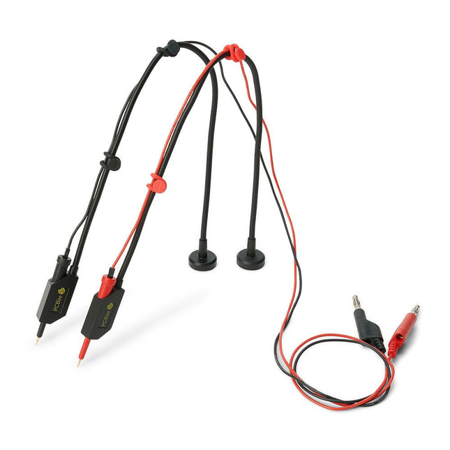
Sensepeek Sensepeek 6011 2x SQ10 Probe for DMM (red/black)
The SQ series of handsfree PCBite probes from Sensepeek are insulated, come with included color-coded cable holders and have a lower point of gravity making them even more stable compared with the original SP series of probes. All the loved features of handsfree measurement, exchangeable fine pitch spring tipped test needle and the minimalistic design is maintained to make traditional sized and handheld probes obsolete. Features All handsfree probes from Sensepeek makes instant measurements or long triggering sessions a breeze. No more soldering wires to connect your probe or complicated tools to setup, just positioning the probe needle on any test point or component in the signal path and release. Saves time and frustration during development, verification and repairs. The minimalist design and the spring-loaded test needle makes it possible to simultaneously measure on fine pitch components and nearby signals. Both length and weight of the SQ probes are perfectly balanced to be used with PCBite PCB holders and base plate which is a must for handsfree function. The probe holder comes with a powerful magnet in the base, as for all PCBite probes and holders which makes the probe easy to place and reposition. The SQ series of probes can be used handheld without the probe holder as they have an insulated grip but their full potential is used when measuring handsfree. Included 2x SQ10 probes and pin tipped test needles (red/black) 2x Banana to dupont test wires (red/black) 1x Set of cable holders (red/black) 2x Extra test needles Downloads User guide
€ 54,45
-
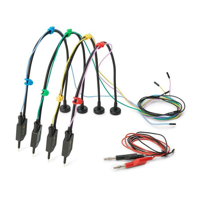
Sensepeek Sensepeek 6005 4x SQ10 Probe incl. Test Wires
The SQ series of handsfree PCBite probes from Sensepeek are insulated, come with included color-coded cable holders and have a lower point of gravity making them even more stable compared with the original SP series of probes. All the loved features of handsfree measurement, exchangeable fine pitch spring tipped test needle and the minimalistic design is maintained to make traditional sized and handheld probes obsolete. Features All handsfree probes from Sensepeek makes instant measurements or long triggering sessions a breeze. No more soldering wires to connect your probe or complicated tools to setup, just positioning the probe needle on any test point or component in the signal path and release. Saves time and frustration during development, verification and repairs. The minimalist design and the spring-loaded test needle makes it possible to simultaneously measure on fine pitch components and nearby signals. Both length and weight of the SQ probes are perfectly balanced to be used with PCBite PCB holders and base plate which is a must for handsfree function. The probe holder comes with a powerful magnet in the base, as for all PCBite probes and holders which makes the probe easy to place and reposition. The SQ series of probes can be used handheld without the probe holder as they have an insulated grip but their full potential is used when measuring handsfree. Included 4x SQ10 probes and pin tipped test needles (black) 2x Banana to dupont test wires (red/black) 5x Dupont to dupont test wires 1x Set of cable holders (4 colors) 4x Extra test needles Downloads User guide
€ 107,69
-

SDRplay SDRplay RSP1B 14-bit SDR Receiver (1 kHz to 2 GHz)
The SDRplay RSP1B is an enhanced version of the popular RSP1A – a powerful, wideband, full-featured 14-bit SDR that covers the RF spectrum from 1 kHz to 2 GHz. The RSP1B comes in a rugged, black-painted steel case and offers significantly improved noise performance. All it needs is a computer and an antenna to deliver excellent communications-receiver functionality. It includes a choice of SDRuno for Windows and the multi-platform SDRconnect software for Windows, macOS, and Linux (supplied free of charge by SDRplay). You can monitor up to 10 MHz of spectrum at a time. A documented API allows developers to create new demodulators or applications for the platform. Features Covers all frequencies from 1 kHz through VLF, LF, MW, HF, VHF, UHF and L-band to 2 GHz, with no gaps Receive, monitor and record up to 10 MHz of spectrum at a time Free use of windows-based SDRuno software which provides an ever-increasing feature-set Strong and growing software support network Calibrated S meter/ RF power and SNR measurement with SDRuno (including datalogging to .CSV file capability) Documented API provided to allow demodulator or application development on multiple platforms Excellent dynamic range for challenging reception conditions Works with popular 3rd party SDR software (including HDSDR, SDR Console and Cubic SDR) ExtIO based plugin available Software upgradeable for future standards Strong and growing software support network API provided to allow demodulator or application development Multiplatform driver and API support including Windows, Linux, Mac, Android and Raspberry Pi Up to 16 individual receivers in any 10 MHz slice of spectrum using SDRuno Calibrated S meter and power measurements with SDRuno Stand-alone windows-based spectrum analyser software available (with sweep, sample and hold features) Ideal for monitoring of ISM/ IoT/ Telemetry bands <2 GHz Ideal for portable operation Specifications Frequency Range 1 kHz – 2 GHz Antenna Connector SMA Antenna Impedance 50 Ohms Current Consumption (Typical) 185 mA (excl. Bias-T) USB Connector USB Type B Maximum Input Power +0 dBm Continuous+10 dBm Short Duration ADC Sample Rates 2-10.66 MSPS ADC Number of Bits 14 bit 2-6.048 MSPS12 bit 6.048-8.064 MSPS10 bit 8.064-9.216 MSPS8 bit >9.216 MSPS Bias-T 4.7 V100 mA guaranteed Reference 0.5ppm 24 MHz TCXO.Frequency error trimmable to 0.01ppm in field. Operating Temperature Range -10˚C to +60˚C Dimensions 98 x 88 x 34 mm Weight 110 g Downloads Datasheet Software RSP1B vs RSPdx vs RSPduo RSP1B RSPdx RSPduo Continuous coverage from 1 kHz to 2 GHz ✓ ✓ ✓ Up to 10 Mhz visible bandwidth ✓ ✓ ✓ 14-bit ADC silicon technology plus multiple high-performance input filters ✓ ✓ ✓ Software selectable AM/FM & DAB broadcast band notch filters ✓ ✓ ✓ 4.7 V Bias-T for powering external remote antenna amplifier ✓ ✓ ✓ Powers over the USB cable with a simple type B socket ✓ ✓ ✓ 50Ω SMA antenna input(s) for 1 kHz to 2 GHz operation (software selectable) 1 2 2 Additional software selectable Hi-Z input for up to 30 Mhz operation ✓ Additional software selectable 50Ω BNC input for up to 200 MHz operation ✓ Additional LF/VLF filter for below 500 kHz ✓ 24 MHz reference clock input (+ output on RSPduo) ✓ ✓ Dual tuners enabling reception on 2 totally independent 2 MHz ranges ✓ Dual tuners enabling diversity reception using SDRuno ✓ Robust and strong plastic case (with internal RF shielding layer) ✓ Rugged black painted steel case ✓ ✓ Overall performance below 2 MHz for MW and LF + ++ + Multiple simultaneous applications + + ++ Performance in challenging fading conditions (*using diversity tuning) + + *++
€ 148,99
-

Raspberry Pi Foundation FPC Display Cable for Raspberry Pi 5 (300 mm)
Raspberry Pi 5 provides two four-lane MIPI connectors, each of which can support either a camera or a display. These connectors use the same 22-way, 0.5 mm-pitch “mini” FPC format as the Compute Module Development Kit, and require adapter cables to connect to the 15-way, 1 mm-pitch “standard” format connectors on current Raspbery Pi camera and display products.These mini-to-standard adapter cables for cameras and displays (note that a camera cable should not be used with a display, and vice versa) are available in 200 mm, 300 mm and 500 mm lengths.
€ 2,95€ 1,18
Best Price
-
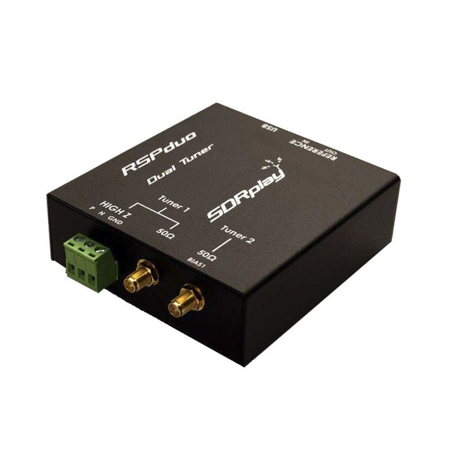
SDRplay SDRplay RSPduo Dual-Tuner 14-bit SDR Receiver (1 kHz to 2 GHz)
The SDRplay RSPduo is a high performance dual-tuner 14-bit SDR receiver. Housed in a high quality steel enclosure, each tuner can operate individually anywhere between 1 kHz and 2 GHz with up to 10 MHz of bandwidth or both tuners can operate simultaneously anywhere between 1 kHz and 2 GHz with up to 2 MHz of bandwidth per tuner. A high stability reference along with external clocking features makes this device ideally suited to industrial, scientific & educational applications. Features Dual tuner provides independent coverage from 1 kHz to 2 GHz using 2 antenna ports simultaneously 14-bit ADC silicon technology Up to 10 MHz visible bandwidth (single tuner mode) or 2 slices of 2 MHz spectrum (dual tuner mode) 3 software-selectable antenna ports (2x 50Ω and 1x 1kΩ high impedance balanced/unbalanced input) High impedance antenna port (1 kHz to 30 MHz) with selectable MW notch filter and choice of 2 pre-selection filters Software selectable AM/FM and DAB broadcast band notch filters for the 2 SMA antenna (1 kHz to 2 GHz) antenna ports External clock input and output enables easy synchronisation to multiple RSPs or external reference clock Powers over the USB cable with a simple type B socket 11 high-selectivity, built in front-end preselection filters on both the 2 SMA antenna ports Software selectable multi-level Low Noise Preamplifier Bias-T power supply for powering antenna-mounted LNA Enclosed in a rugged black painted steel case. SDRuno – World Class SDR software for Windows Documented API for new apps development Specifications Frequency Range 1 kHz – 2 GHz Antenna Connector SMA Antenna Impedance 50 Ohms Current Consumption (Typical) Single Tuner Mode: 180 mA (excl. Bias-T)Dual Tuner Mode: 280 mA (excl. Bias-T) USB Connector USB-B Maximum Input Power +0 dBm Continuous+10 dBm Short Duration ADC Sample Rates 2-10.66 MSPS ADC Number of Bits 14 bit 2-6.048 MSPS12 bit 6.048-8.064 MSPS10 bit 8.064-9.216 MSPS8 bit >9.216 MSPS Bias-T 4.7 V100 mA guaranteed Reference High Temperature Stability (0.5ppm) 24 MHz TCXO.Frequency error trimmable to 0.01ppm in field. Operating Temperature Range −10˚C to +60˚C Dimensions 98 x 94 x 33 mm Weight 315 g Downloads Datasheet Detailed Technical Information Software RSPdx-R2 vs RSPduo RSPdx-R2 RSPduo Continuous coverage from 1 kHz to 2 GHz ✓ ✓ Up to 10 MHz visible bandwidth ✓ ✓ 14-bit ADC silicon technology plus multiple high-performance input filters ✓ ✓ Software selectable AM/FM & DAB broadcast band notch filters ✓ ✓ 4.7 V Bias-T for powering external remote antenna amplifier ✓ ✓ Powers over the USB cable with a simple type B socket ✓ ✓ 50Ω SMA antenna input(s) for 1 kHz to 2 GHz operation (software selectable) 2 2 Additional software selectable Hi-Z input for up to 30 Mhz operation ✓ Additional software selectable 50Ω BNC input for up to 200 MHz operation ✓ Additional LF/VLF filter for below 500 kHz ✓ 24 MHz reference clock input (+ output on RSPduo) ✓ ✓ Dual tuners enabling reception on 2 totally independent 2 MHz ranges ✓ Dual tuners enabling diversity reception using SDRuno ✓ Rugged black painted steel case ✓ ✓ Overall performance below 2 MHz for MW and LF ++ + Multiple simultaneous applications + ++ Performance in challenging fading conditions (*using diversity tuning) + *++
€ 287,98
-

OWON OWON SPE6103 DC Power Supply (300 W)
The OWON SPE6103 is a 1-channel DC power supply (300 W) in a small body with features like over voltage and over current protection. It has a high resolution of 10 mV/1 mA. The 2.8" LCD displays the following information (constant voltage output, constant current output, cumulative running time, actual output power, channel output status, actual voltage output, actual current output). Features Small body for easy carry High resolution: 10 mV/1 mA List waveform editing output, editable 10 groups of timing output function Low ripple/noise Over voltage / over current protection Output voltage and current curve monitoring function Intelligent temperature control fan cooling 2.8-inch TFT LCD display USB communication interface, support SCPI Specifications Model SPE6102 SPE6103 Rated Output (0-40°C) Voltage 0-60 V 0-60 V Current 10 A 10 A Output Power 200 W 300 W USB Output 5 V/1 A (SPE Series) or suppout QC2.0, QC3.0, BC1.2, Apple, Huawei, Samsung fast charging protocols (optional) Load Regulation Voltage ≤30 mV Current ≤20 mA Power Regulation Voltage ≤30 mV Current ≤20 mA Setting Resolution Voltage 10 mV Current 1 mA Readback Resolution Voltage 10 mV Current 1 mA Value Resolution (within 12 months) (25 ±5°C) Voltage ≤0.1% ±30 mV ≤0.1% ±30 mV Current ≤0.05% ±10 mA Readback Value Resolution (25 ±5°C) Voltage ≤0.1% ±30 mV ≤0.1% ±30 mV Current Ripple/Noise Voltage (Vp-p) ≤50mVp-p ≤50mVp-p Voltage (rms) ≤5mVrms ≤5mVrms Current (rms) ≤30mAp-p Output temperature coefficient (0-40°C) Voltage 100ppm/°C Current 200ppm/°C Readback temperature coefficient Voltage 100ppm/°C Current 200ppm/°C Response Time (50-100% rated load) ≤1.0ms Storage 4 groups of data Working Temperature 0-40°C Included 1x OWON SPE6102 1x Power Cord 1x Quick Guide 1x USB Cable 1x Fuse Downloads User Manual Programming Manual Software
€ 125,00
-

OWON OWON OW18B True RMS Multimeter
Features Data-logger & Multimeter & Thermometer 3 (5/6) digits True RMS test supported BLE 4.0 wireless transmission, more stable, less power consumption Chart and Diagram mode, to analyze your data Supports NCV Voice Broadcast simplifies testing Flashlight function Built-in offline recording function Supports Android, iOS Included Test leads K-type thermocouple 9 V Battery Bolt driver Crocodile clip Quick guide
€ 39,63
-
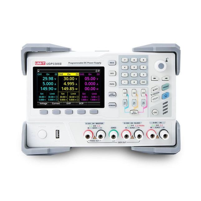
Uni-Trend UNI-T UDP3305S-E DC Power Supply (328 W)
The UDP3305S-E is a high-performance programmable linear DC power supply. It has a clear LCD user interface, excellent performance indicators, a variety of analysis functions and communication interfaces. It can meet the diversified test needs of users. It aims to provide cost-effective DC programmable power supply equipment for teaching, scientific research, industry and other fields. LCD interactive interface Using a 4.3-inch high-definition display screen, it provides users with a man-machine interface with rich functions and simple operation, which can display the current set output voltage/current, actual output voltage/current and protection output voltage/current value of the power supply in real time. The functional interface is simple and comprehensive, easy to operate. One-key setting for series and parallel The series-parallel connection between CH1 and CH2 of the main channel can be realized without external connection, which simplifies the connection and makes the test easier. List/Delayer function With list and delay setting functions, it can set up to 2048 sets of data according to test requirements, and the number of cycles can reach 99999. It is used with waveform templates, which is very convenient for cycle testing and aging testing. Rich remote control interface Standard RS232 communication interface, Ethernet interface, Digital I/O and master and slave USB interfaces, can be controlled by remote connection to Ethernet, or through RS232 and USB, with the host computer software to achieve software control. Specifications Type Linear DC power supply Channels 4 Total power 328 W Output voltage CH1/CH2: 0~30 VCH3: 0~6 VCH4: 5 V Output current CH1/CH2: 0~5 ACH3: 0~3 ACH4: 2 A Resolution 10 mV, 1 mA Setting accuracy 0.3% +20 mV<0.2% +5 mA Connectivity USB Device, RS-232, LAN, USB host, Digital I/O Included 1x UDP3305S-E DC Power Supply 1x Power cord 1x USB cable Downloads Datasheet User manual Programming manual Software V1.0 Firmware V1.10
€ 396,54
-

SunFounder Universal Maker Sensor Kit (for Raspberry Pi, Pico W, Arduino, ESP32)
Discover endless creativity with the Universal Maker Sensor Kit, designed for use with Raspberry Pi, Pico W, Arduino, and ESP32. This versatile kit offers compatibility across popular development platforms, including Arduino Uno R4 Minima/WiFi, Uno R3, Mega 2560, Raspberry Pi 5, 4, 3B+, 3B, Zero, Pico W, and ESP32. Featuring over 35 sensors, actuators, and displays, it's perfect for projects ranging from environmental monitoring and smart home automation to robotics and interactive gaming. Step-by-step tutorials in C/C++, Python, and MicroPython guide beginners and experienced makers alike through 169 exciting projects. Features Wide Compatibility: Fully supports Arduino (Uno R3, Uno R4 Minima/WiFi, Mega 2560), Raspberry Pi (5, 4, 3B+, 3B, Zero, Pico W), and ESP32, enabling extensive flexibility across numerous development platforms. Includes instructions for building 169 projects. Comprehensive Components: Features more than 35 sensors, actuators, and display modules suitable for diverse projects such as environmental monitoring, smart home automation, robotics, and interactive game controllers. Detailed Tutorials: Provides clear, step-by-step tutorials covering Arduino, Raspberry Pi, Pico W, ESP32, and each included component. Tutorials are available in C/C++, Python, and MicroPython, catering effectively to both beginners and experienced makers. Suitable for All Skill Levels: Offers structured projects designed to guide users seamlessly from beginner to advanced proficiency in electronics and programming, enhancing creativity and technical expertise. Included Breadboard Button Module Capacitive Soil Moisture Module Flame Sensor Module Gas/Smoke Sensor Module (MQ2) Gyroscope & Accelerometer Module (MPU6050) Hall Sensor Module Infrared Speed Sensor Module IR Obstacle Avoidance Sensor Module Joystick Module PCF8591 ADC DAC Converter Module Photoresistor Module PIR Motion Module (HC-SR501) Potentiometer Module Pulse Oximeter and Heart Rate Sensor Module (MAX30102) Raindrop Detection Module Real Time Clock Module (DS1302) Rotary Encoder Module Temperature Sensor Module (DS18B20) Temperature and Humidity Sensor Module (DHT11) Temperature, Humidity & Pressure Sensor (BMP280) Time of Flight Micro-LIDAR Distance Sensor (VL53L0X) Touch Sensor Module Ultrasonic Sensor Module (HC-SR04) Vibration Sensor Module (SW-420) Water Level Sensor Module I²C LCD 1602 OLED Display Module (SSD1306) RGB LED Module Traffic Light Module 5 V Relay Module Centrifugal Pump L9110 Motor Driver Module Passive Buzzer Module Servo Motor (SG90) TT Motor ESP8266 Module JDY-31 Bluetooth Module Power Supply Module Documentation Online Tutorial
-

iFixit iFixit Essential Electronics Toolkit
The iFixit Essential Electronics Toolkit is what you need for the most essential electronics repairs – like screen and battery swaps – and everything you need for most household DIY fixes. Get started in electronics repair with all the bits and precision tools to handle your most urgent screen breaks and battery swaps. Or simply upgrade your home DIY toolkit with what you need to service door knobs, home appliances, eyeglasses, and more. Included Magnetized Driver Handle Angled Precision Tweezers Spudger Jimmy iFixit Opening Tool iFixit Opening Picks set of 6 Suction Handle Easy-to-Open Magnetized Case Lid with Built-in Sorting Tray Sixteen 4mm Precision Screwdriver Bits Phillips - 000, 00, 0, 1 Pentalobe - P2, P5 Flathead - 1 mm, 2.5 mm, 4 mm Torx - T4, T5 Torx Security - TR6, TR8, TR10 Tri-Point - Y000 SIM Eject Bit Specifications Bit Metal: 6150 Steel Driver Material: Polymer Case Material: ABS Foam: EVA
€ 34,95
-
Raspberry Pi Foundation FPC Display Cable for Raspberry Pi 5 (500 mm)
Raspberry Pi 5 provides two four-lane MIPI connectors, each of which can support either a camera or a display. These connectors use the same 22-way, 0.5 mm-pitch “mini” FPC format as the Compute Module Development Kit, and require adapter cables to connect to the 15-way, 1 mm-pitch “standard” format connectors on current Raspbery Pi camera and display products.These mini-to-standard adapter cables for cameras and displays (note that a camera cable should not be used with a display, and vice versa) are available in 200 mm, 300 mm and 500 mm lengths.
€ 3,95€ 1,58
Best Price
-
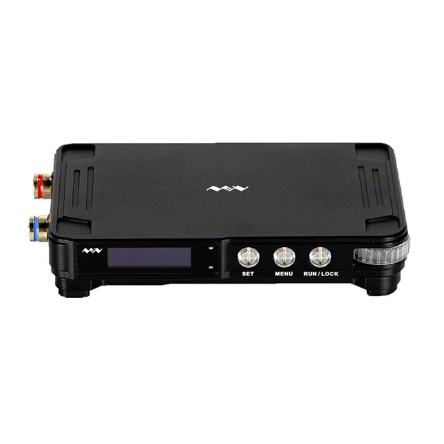
Miniware Miniware MDP-P906 Digital Power Supply (300 W)
MDP-P906 has a built-in cooling fan, and maximum output power of up to 300 W, which meets a wider range of testing needs and application scenarios. Through 2.4 GHz wireless communication, it can be connected to MDP-M01 Smart Digital Monitor module to realize the free combination of multiple channels of 300 W per channel. MDP-P906 has the index, stability and reliability comparable to a professional power supply. It can output pure current, and provide powerful functions such as programmable output, timing output, timing control, automatic compensation, boost mode, etc., making itself a real cost-effective, smart and customized programmable linear DC power supply. MDP-P906 adopts a precision CNC machined aluminum alloy shell, with fine workmanship, novel, mini and beautiful appearance, it completely subverts the rigid image of traditional desktop power supply. With stackable modular design and wireless communication function, MDP-P906 can work independently or paired, both on the workbench, and be carried out for on-site maintenance. MDP-P906 is a perfect solution for electronic engineer, especially field application engineers to meet different needs of power sources. Built-in silent cooling fan, instant cooling, ensure a stable and efficient output! Smart linear compensation, constant voltage & constant current Positive & negative output, series boost, parallel current sharing Applications Universal tests and teaching experiments in R&D laboratory Maintenance of digital products Property verification and fault diagnosis of devices and circuits Emergency power supply for model airplanes and vehicles Power supply testing of RF and microwave circuits or modules Quality control and quality inspection Supply purified power for high-accuracy digital-analog hybrid circuits and Hi-Fi audio devices Specifications Input DC 4.2-30 V/14 A (Max)QC 3.0/PD2.0, 20 V/5 A (Max) Output 0-30 V/0-10 A, 300 W (Max) Conversion efficiency 95% Output resolution 10 mV/2 mA, up to 1 mV/1 mA via Display Control module Output accuracy 0.03%+5 mV0.05%+2 mV Adjustment rate Load adjustment rate <±0.01%Power adjustment rate <±0.01% Ripple and noise <250 uVrms, 3 mVpp; 2 mArms Transient response <4 uS Safety protections Input over-voltage, under-voltage, reverse connection protection, output over-current, back-flow protection and over-temperature protection Others Automatically shut-down and enter micro-power modeSupport USB firmware upgrade Dimensions 112 x 66 x 20 mm Weight 181 g Included 1x MDP-P906 Digital Power Supply 2x Output Cable 1x User Manual Downloads User Manual v1.1 Firmware v1.32
€ 171,95
-

iFixit iFixit Manta Driver Kit
This kit includes iFixit's widest assortment of bits, complete with every driver head you’ll need to tackle any repair or DIY project. It includes standard bits like Phillips and Flathead in a full range of sizes to handle everything from precision electronics repair to home DIY projects. And it wouldn’t be an iFixit bit set if it didn’t include all the exotic bits from Pentalobes for Apple iPhone and MacBook repair to Gamebits for your vintage Nintendo consoles. All of the next-gen bit sets have been re-designed in order to maximize convenience and usability. The bit set lid is held in place with magnets to increase product lifespan (no more broken hinges or clasps) and also mounts to the back of the bit set case to keep it out of the way while you do your work. If you need help keeping your screws and parts organized, you can use the lid’s integrated sorting tray. The 4 mm bits have been adjusted and have now a longer neck for a deeper and more precise reach. Toolkit Includes Easy-to-Open Magnetized Case Lid with Built-in Sorting Tray 4 mm Aluminum Bit Driver 1/4' Aluminum Bit Driver 4 mm Screwdriver Bits Phillips - 000, 00, 0 Flathead - 1, 1.5, 2, 2.5, 3, 3.5 mm Torx - T2, T3, T4, T5 Torx Security - TR6, TR7, TR8 Pentalobe - P2, P5, P6 JIS - 000, 00, 0, 1 Hex - 0.7, 0.9, 1.3, 1.5 mm Hex Security - 2, 2.5, 3, 3.5 mm Tri-point - Y000, Y00, Y0, Y1 Nut driver - 2.5, 3, 3.5, 4, 4.5, 5, 5.5 mm Gamebit - 3.8, 4.5 mm Spanner - 4, 6 Triangle - 2, 2.2, 2.6, 3 mm Oval Bit iPhone Standoff Bit Sim Eject Bit Magnetic Pickup Bit 1/4' Screwdriver Bits Phillips - 1, 2, 3 Flathead - 4, 5, 6, 7, 8 mm Hex Security - 4, 5, 6, 7, 8 mm Hex Security SAE - 1/8, 9/64, 5/32, 3/16, 7/32, 1/4 Pozidriv - PZ0, PZ1, PZ2, PZ3 Torq-set - 6, 8, 10 Spanner - 8, 10, 12 Square - 0, 1, 2, 3 Spline - M5, M6, M8 Torx Security - TR9, TR10, TR15, TR20, TR25, TR27, TR30, TR35, TR40 Tri-wing 1, 2, 3, 4 Clutch 1, 2, 3 Schrader Valve Hook Drive 1/4' to 4 mm Adapter 1/4' Driver to 1/4' Socket 1/4' Driver to 3/8' Socket 1/4' Socket to 1/4' Driver Specifications Bit Metal: 6150 Steel Driver Material: Anodized Aluminum Case Material: ABS Foam: EVA
€ 64,95
-
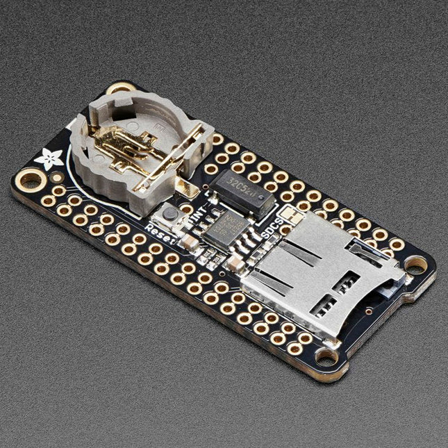
Adafruit Adafruit Adalogger FeatherWing (RTC + SD Add-on)
This FeatherWing will make it easy to add data logging to any Feather Board you might have. You get both an I²C real-time clock (PCF8523) with 32 KHz crystal and battery backup, and a microSD socket that connects to the SPI port pins (+ extra pin for CS). Note: FeatherWing doesn't come with a microSD card. A CR1220 coin cell is required to use the RTC battery-backup capabilities. If you're not using the RTC part of the FeatherWing, a battery is not required. To talk to the microSD card socket Arduino's default SD library is recommended. Some light soldering is required to attach the headers onto the Wing. Pinouts Power pins On the bottom row, the 3.3 V (second from left) and GND (fourth from left) pin are used to power the SD card and RTC (to take a load off the coin cell battery when main power is available) RTC & I²C Pins In the top right SDA (rightmost) and SCL (to the left of SDA) are used to talk to the RTC chip. SCL - I²C clock pin to connect to your microcontroller's I2C clock line. This pin has a 10 kΩ pull-up resistor to 3.3 V SDA - I²C data pin to connect to your microcontroller's I2C data line. This pin has a 10 kΩ pull-up resistor to 3.3 V There's also a breakout for INT which is the output pin from the RTC. It can be used as an interrupt output or it could also be used to generate a square wave. Note that this pin is an open drain - you must enable the internal pull-up on whatever digital pin it is connected to. SD & SPI Pins Starting from the left you've got SPI Clock (SCK) - output from feather to wing SPI Master Out Slave In (MOSI) - output from feather to wing SPI Master In Slave Out (MISO) - input from wing to feather These pins are in the same location on every Feather. They are used for communicating with the SD card. When the SD card is not inserted, these pins are completely free.
-

Raspberry Pi Foundation Raspberry Pi Compute Module 5 Development Kit
The Raspberry Pi Compute Module 5 Development Kit provides an ideal platform for prototyping embedded solutions. This all-in-one kit contains the Compute Module 5, the Compute Module 5 IO Board and all necessary accessories to start your product design. Compute Module 5 (CM5104032) 2.4 GHz quad-core 64-bit Arm Cortex-A76 CPU VideoCore VII GPU, supporting OpenGL ES 3.1 and Vulkan 1.3 4 GB LPDDR4X-4267 SDRAM 32 GB MLC eMMC memory 1x Dual 4Kp60 HDMI display output 1x 4Kp60 HEVC decoder 1x Dual-band 802.11ac Wi-Fi and Bluetooth 5.0 2x USB 3.0 interfaces, supporting simultaneous 5 Gbps operation 1x Gigabit Ethernet, with IEEE 1588 support 2x 4-lane MIPI camera/display transceivers 1x PCIe 2.0 interface for fast peripherals 30 GPIOs, supporting 1.8 V or 3.3 V operation Peripherals: UART, SPI, I²C, I²S, SDIO, and PWM Compute Module 5 IO Board 1x Standard 40-pin GPIO 2x Full-size HDMI 2.0 2x 4-lane MIPI DSI/CSI-2 FPC (22-pin, 0.5 mm pitch cable) 2x USB 3.0 1x Gigabit Ethernet jack with PoE+ support (requires a separate Raspberry Pi PoE+ HAT+) 1x M.2 M-key PCIe socket (for 2230, 2242, 2260 and 2280 modules) 1x microSD card socket (for use with Lite modules) 1x RTC battery socket 1x 4-pin fan connector Compute Module 5 IO Case The metal case transforms the IO Board into a fully enclosed, industrial-grade computer. Designed specifically for the Raspberry Pi Compute Module 5, the IO Case features a built-in fan that connects to the IO Board's 4-pin fan connector, ensuring enhanced thermal performance. Included 1x Raspberry Pi Compute Module 5 (Wireless, 4 GB RAM, 32 GB eMMC) 1x Raspberry Pi Compute Module 5 IO Board (supplied pre-fitted inside the IO Case) 1x Raspberry Pi Compute Module 5 IO Case 1x Raspberry Pi Compute Module 5 Cooler 1x Raspberry Pi Antenna Kit 1x Raspberry Pi 27 W USB-C PD Power Supply (EU) 2x Raspberry Pi HDMI to HDMI cables 1x Raspberry Pi USB-A to USB-C cable Downloads Datasheet (Compute Module 5) Datasheet (IO Board) Datasheet (IO Case) Datasheet (Cooler) Datasheet (Antenna Kit)
-

Sensepeek Sensepeek 6014 SQ200 (200 MHz handsfree Oscilloscope Probe)
The SQ series of handsfree probes from Sensepeek have a lower point of gravity making them even more stable compared with the original SP series of handsfree probes. All probes in the SQ series are also insulated and can be used handheld as any traditional probe but their full potential is used when measuring handsfree. Features The SQ series of handsfree probes from Sensepeek have a lower point of gravity making them even more stable compared with the original SP series of handsfree probes. All probes in the SQ series are also insulated and can be used handheld as any traditional probe but their full potential is used when measuring handsfree. The SQ series of oscilloscope probes also includes more ground options, have probe tip protection, longer cable and support for oscilloscopes with automatic scaling (10:1). All the loved features of handsfree measurement, exchangeable fine pitch spring tipped test needle, color-coded cable holders and the minimalistic design is maintained to make traditional sized and handheld probes obsolete. Both length and weight of the SQ probes are perfectly balanced to be used with PCBite PCB holders and base plate which is a must for handsfree function. Included 1x SQ200 200 MHz probe with spring tipped test needle 1x SQ probe holder for handsfree measurement 1x Testhook with detachable cables (5 cm & 10 cm) for convenient ground connection 1x Alligator cable for convenient ground connection 1x Standard ground spring, for handheld measurements at rated bandwidth 1x Unique ground spring, for total handsfree measurements at rated bandwidth 1x Set of color coded cable holders (4 colors) 1x Probe tip protection 1x Extra test needle Downloads User Guide SQXX0 Rev1.2
€ 82,52
-
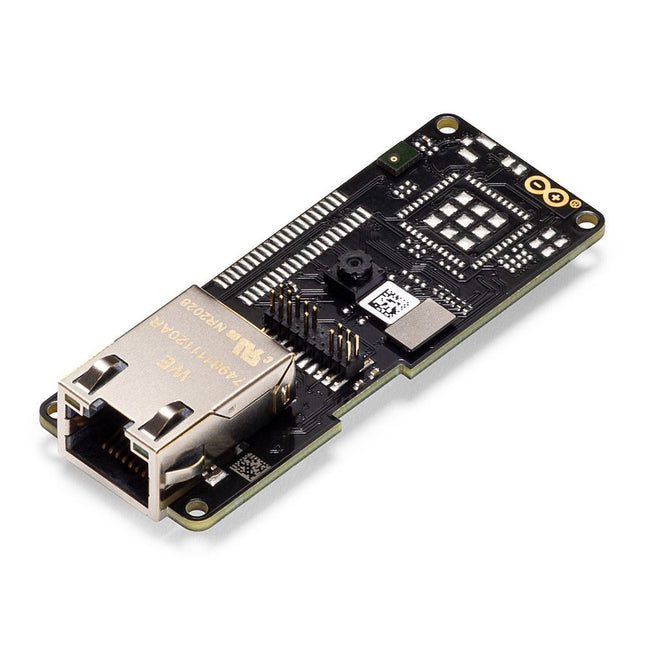
Arduino Arduino Pro Portenta Vision Shield (Ethernet)
The Arduino Pro Portenta Vision Shield brings industry-rated features to your Portenta. This hardware add-on will let you run embedded computer vision applications, connect wirelessly or via Ethernet to the Arduino Cloud or your own infrastructure, and activate your system upon the detection of sound events. Features 324x324 pixels camera sensor: use one of the cores in Portenta to run image recognition algorithms using the OpenMV for Arduino editor 100 Mbps Ethernet connector: get your Portenta H7 connected to the wired Internet 2 onboard microphones for directional sound detection: capture and analyse sound in real-time JTAG connector: perform low-level debugging of your Portenta board or special firmware updates using an external programmer SD-Card connector: store your captured data in the card, or read configuration files The Vision Shield has been designed to fit on top of the Arduino Portenta family. The Portenta boards feature multicore 32-bit ARM Cortex processors running at hundreds of megahertz, with megabytes of program memory and RAM. Portenta boards come with WiFi and Bluetooth. Embedded Computer Vision Made Easy Arduino has teamed up with OpenMV to offer you a free license to the OpenMV IDE, an easy way into computer vision using MicroPython as a programming paradigm. Download the OpenMV for Arduino Editor from our professional tutorials site and browse through the examples we have prepared for you inside the OpenMV IDE. Companies across the whole world are already building their commercial products based on this simple-yet-powerful approach to detect, filter, and classify images, QR codes, and others. Debugging With Professional Tools Connect your Portenta H7 to a professional debugger through the JTAG connector. Use professional software tools like the ones from Lauterbach or Segger on top of your board to debug your code step by step. The Vision Shield exposes the required pins for you to plug in your external JTAG. Camera Himax HM-01B0 camera module Resolution 320 x 320 active pixel resolution with support for QVGA Image sensor High sensitivity 3.6μ BrightSense pixel technology Microphone 2 x MP34DT05 Length 66 mm Width 25 mm Weight 11 gr For more information, check out the tutorials provided by Arduino here.
€ 69,95€ 19,95
Best Price
-
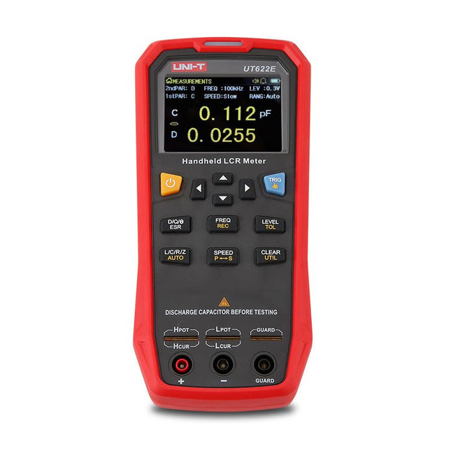
Uni-Trend UNI-T UT622E LCR Meter
The UT622E handheld LCR meter features powerful functions, high accuracy, fast speed, and long standby time. With a clear and intuitive 2.8-inch TFT LCD display, large-capacity rechargeable battery, and 100 kHz test frequency, the meter can be used for longstanding accurate and convenient measurement in any occasion. It is suitable for the measurement and screening of inductance, capacitance, and resistance in laboratories, production lines, maintenance points, etc. Features Max. test frequency: 100 kHz Accuracy: 0.1% Display count: 99999 Max. test rate: 20 times/s DCR: Yes Connectivity: Mini-USB Display: 2.8" TFT LCD Specifications Testfrequency 100 Hz, 120 Hz, 1 kHz, 10 kHz, 100 kHz Test level 0.1 Vmrs, 0.3 Vrms, 1 Vrms Output impedance 100 Ω Measurement parameters Primary: L/C/R/Z/DCRSecondary: D/Q/Θ/ESR DSR speed test Fast (20 times/s), medium (5 times/s), or slow (2 times/s) Range Auto/Hold Tolerance range 1%~20% Equivalent mode Series/Parallel Clearing connection Open/Short circuit Fuse of test ports 0.1 A/250 V Communication interface Mini-USB MAX reading of primary parameters 99999 MIN resolution 0.0001 Maximum accuracy 0.10% L 0.00 µH~99.999 H C 0.00 pF~99.999 mF Z/R 0.0000 Ω~9.9999 MΩ ESR 0.0000 Ω~999.99 Ω D 0.0000~9.9999 Q 0.0000~99999 Θ -179.9°~179.9° DCR 0.01 mΩ~20.000 MΩ Power supply 3.7 V/1800 mAh lithium polymer battery Display 2.8" TFT LCD (320x240) Dimensions 93 x 192 x 44 mm Weight 420 g Included UT622E LCR meter Short circuit board Four-terminal kelvin test leads USB cable Manual Downloads Datasheet Manual Software
€ 325,49
-
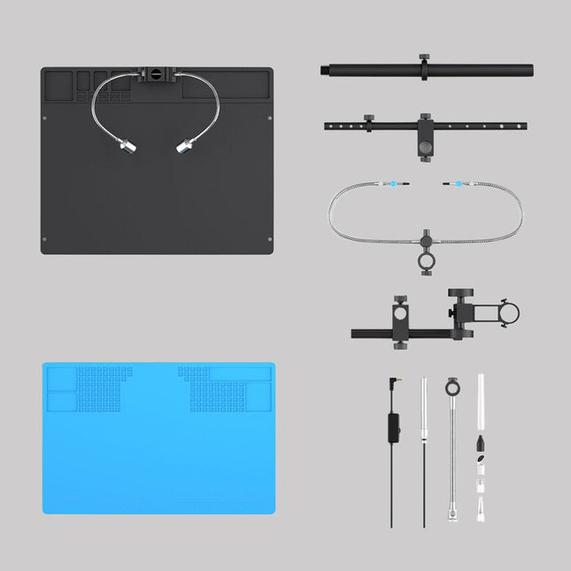
Andonstar Andonstar Max Station Upgrade Set for AD409 Models
Upgrade your Andonstar AD409, AD409 Pro, or AD409 Pro-ES to the Max model with this enhancement kit. The newly designed, oversized Max station provides ample workspace, making it perfect for larger projects and ideal for professional soldering tasks. Included 1x Stand with 2 LEDs 1x Repair mat 1x Beam 1x Column 1x Tool holder 1x Soldering Helping Hands
€ 60,00
-

OWON OWON HDS2202s 2-ch Oscilloscope (200 MHz) + Multimeter + Signal Generator
The OWON HDS2202s is a portable 3-in-1 multifunctional tester, which can be used as a 2-ch oscilloscope with a bandwidth of 200 MHz, multimeter and signal generator. It features a high-contrast 3.5-inch color display suitable for outdoor facility maintenance, rapid on-site measurement, automobile maintenance, power detection. etc. Features Oscilloscope + multimeter + waveform generator, multifunction in one 3.5-inch high-resolution, high-contrast color LCD display, suitable for outdoor use 18650 lithium battery, can work continuously for 3-6 hours USB Type-C interface, support power bank, support PC software connection Self-calibration function SCPI supported, facilitate secondary development Specifications Bandwidth 200 MHz Channels 2-ch Oscilloscope + 1-ch Generator Sample Rate 1 GSa/s Acquisition Model Normal, Peak detect Record Length 8K Display 3.5-inch LCD Waveform Refresh Rate 10,000 wfrms/s Input Coupling DC, AC, and Ground Input Impedance 1 MΩ ±2%, in parallel with 16pF ±10pF Probe Attenuation Factors 1X,10X,100X,1000X,10000X Max. input Voltage 400 V (DC+AC, PK-PK, 1MΩ input impedance) (10:1 probe attenuation) Bandwidth Limit (typical) 20 MHz Horizontal Scale 2ns/div - 1000s/div, step by 1 - 2 - 5 Vertical Sensitivity 10mV/div - 10V/div Vertical Resolution 8 bits Trigger Type Edge Trigger Modes Auto, Normal, single Automatic Measurement Frequency, Period, Amplitude, Max, Min, Mean, PK-PK Cursor Measurement ΔV, ΔT, ΔT&ΔV between cursors Communication Interface USB Type-C Multimeter Specifications Max. Resolution 20,000 counts Testing Mode Voltage, Current, Resistance, Capacitance, Diode, and Continuity test Input Impedance 10 MΩ Max Input Voltage AC 750 V, DC 1000 V Max Input Current DC: 10 A, AC: 10 A Diode 0-2 V Waveform Generator Specifications Frequency Output Sine 0.1 Hz - 25 MHz Square 0.1 Hz - 5MHz Ramp 0.1 Hz - 1 MHz Pulse 0.1 Hz - 5 MHz Arbitrary 0.1 Hz - 5 MHz Sampling Rate 125 MSa/s Channel 1-ch Amplitude Range (high impedance) 20 mVpp - 5 Vpp Waveform Length 8K Vertical Resolution 14 bits Output Impedance 50Ω Included 1x OWON HDS2202s 1x Power adapter 1x USB cable 1x Passive probes 2x Crocodile clip cable 1x Set of multimeter probes (one red and one black) 1x User manual 1x Probe correction adjustment knife Downloads User Manual Specifications SCPI Protocol Quick Guide Software
€ 242,00
-
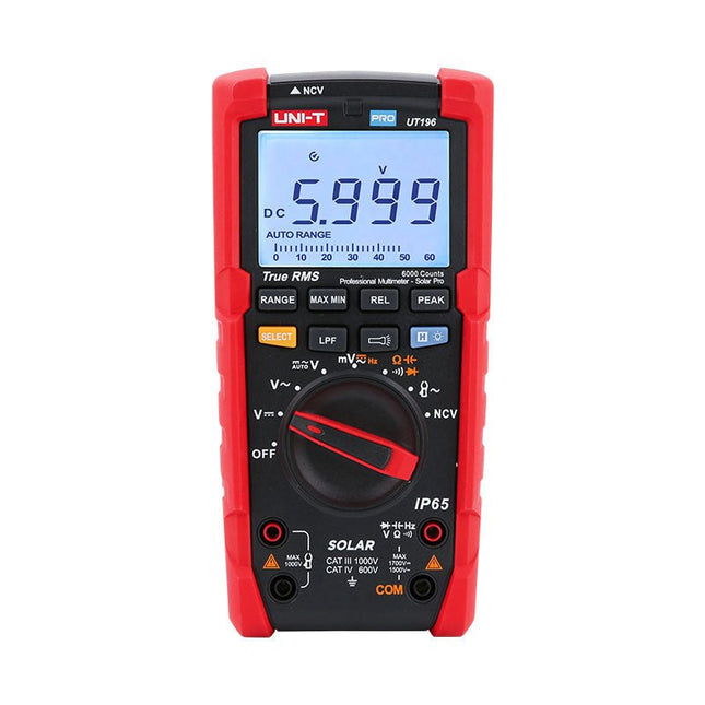
Uni-Trend UNI-T UT196 True RMS Solar Multimeter
The UT196 True RMS solar multimeter is an ideal tool for solar power system maintenance. This rugged meter is designed for technicians who work in rugged outdoor environments. UT196 can measure up to 1700 V DC and 1500 V AC voltages, and 3000 A AC current with an external current clamp sensor. This solar meter offers IP65 protection and able to withstand 2 m drop as well. The UT196 solar multimeter is designed with 1700 V DC, 1500 Vrms AC overload protection and tested for safe usage in CAT III 1000 V, CAT IV 600 V environments. Features True RMS Measure up to 1700 V DC and 1500 V AC for high voltage applications e.g. solar array, wind IP65 protection CAT III 1000V, CAT IV 600 V Analog bar Frequency response: 45 Hz~1 kHz Low-pass filter function Low impedance mode Built-in flashlight, bright backlight and visual alarm Applications High DC voltage measurement Output voltage and frequency measurement Voltage and frequency measurement Current and frequency measurement Specifications Range UT196 DC voltage (V) 1700 V ±0.2% +5 AC voltage (V) 1500 V ±0.8% +3 Frequency (Hz) 1 MHz ±0.08% +4 Resistance (Ω) 60 MΩ ±0.8% +2 Capacitance (F) 60 mF ±1.9% +5 Power 9 V battery Dimensions 195 x 95 x 58 mm Included UT196 Solar Multimeter Battery Test leads Downloads Datasheet Manual
€ 129,63
-
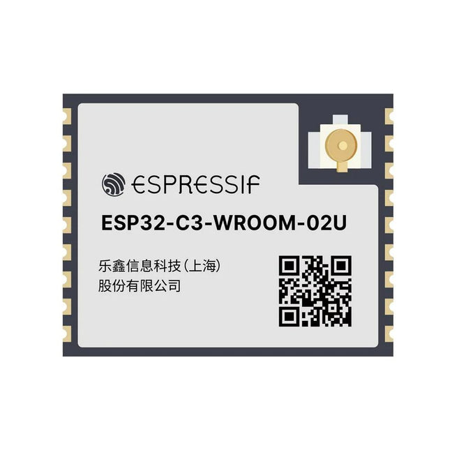
Espressif ESP32-C3-WROOM-02U-N4
ESP32-C3-WROOM-02U is a general-purpose Wi-Fi and Bluetooth LE module. The rich set of peripherals and high performance make the module an ideal choice for smart homes, industrial automation, health care, consumer electronics, etc. ESP32-C3-WROOM-02U features an external SPI flash and comes with a connector for an external antenna. ESP32-C3-WROOM-02U has an operating ambient temperature option of –40∼85°C, embedded with the ESP32-C3 chip. ESP32-C3 has a 32-bit RISC-V single-core processor. It integrates a rich set of peripherals, ranging from UART, I²C, I²S, remote control peripheral, LED PWM controller, general DMA controller, TWAI controller, USB Serial/JTAG controller, temperature sensor, ADC, etc. It also includes SPI, Dual SPI and Quad SPI interfaces. Features Flash: 4 MB (Quad SPI) Dimensions: 18.0 x 20.0 x 3.2 mm Downloads Datasheet
€ 7,95€ 2,95
Best Price


