OWON VDS1022I 2-channel USB oscilloscope (25 MHz) is a oscilloscope for use with a computer. It is powered by USB and has a small size, making it easy to take it with you. The oscilloscope is very economical. It has a shielded USB connection, reducing interference and protecting the computer against over-voltage. The multi port on the scope can be used for external triggering, trigger out or Pass / Fail output.
Features
25 MHz bandwidth, and max 1 GS/s real-time sample rate
10M record length
Friendly UI: FFT, or X-Y, and waveform 2 views displayed on the same screen
Multi-trigger option: edge, video, slope, pulse, and alternate
USB isolation – less signal inference, more PC protection
USB bus powering, and LAN remote control (optional)
Ultra-thin body design, easy portability
Specifications
Bandwidth
25 MHz
Channel
2+1 (multi)
Sample Rate
100 MSa/s
Horizontal Scale (s/div)
5 ns/div~100s/div, step by 1~2~5
Record Length
5K
Max Input Voltage
400 V (PK - PK)
(DC+AC, PK - PK)
40 V (PK - PK) (DC+AC, PK - PK)
Vertical Resolution (A/D)
8 bits (2 channels simultaneously)
Model
VDS1022I
Vertical Sensitivity
5 mV/div~5 V/div
Trigger Type
Edge, Pulse, Video, Slope, and Alternate
Trigger Mode
Auto, Normal, and Single
Acquisition Mode
Sample, Peak Detect, and Average
Waveform Math
+, -, ×, ÷, invert, FFT
Communication Interface
USB 2.0 (isolation)
Multi-function
Interface
Signal Type
Level Standard
TTL
Power Supply
5.0 V/1 A
Power Consumption
≤2.5 W
Dimensions (W × H × D)
170 x 120 x 18 mm
Weight
0.26 kg
Included
1x OWON VDS1022I oscilloscope
1x CD-ROM
1x Quick start guide
2x Oscilloscope probe
1x Probe tool
1x Power adapter
1x USB cable
1x Silicone case protectors
1x Power cable
Downloads
Datasheet
User manual
SCPI protocol
USB driver
The FRDM-MCXN947 is a compact and versatile development board designed for rapid prototyping with MCX N94 and N54 microcontrollers. It features industry-standard headers for easy access to the MCU's I/Os, integrated open-standard serial interfaces, external flash memory, and an onboard MCU-Link debugger.
Specifications
Microcontroller
MCX-N947 Dual Arm Cortex-M33 cores @ 150 MHz each with optimized performance efficiency, up to 2 MB dual-bank flash with optional full ECC RAM, External flash
Accelerators: Neural Processing Unit, PowerQuad, Smart DMA, etc.
Memory Expansion
*DNP Micro SD card socket
Connectivity
Ethernet Phy and connector
HS USB-C connectors
SPI/I²C/UART connector (PMOD/mikroBUS, DNP)
WiFi connector (PMOD/mikroBUS, DNP)
CAN-FD transceiver
Debug
On-board MCU-Link debugger with CMSIS-DAP
JTAG/SWD connector
Sensor
P3T1755 I³C/I²C Temp Sensor, Touch Pad
Expansion Options
Arduino Header (with FRDM expansion rows)
FRDM Header
FlexIO/LCD Header
SmartDMA/Camera Header
Pmod *DNP
mikroBUS
User Interface
RGB user LED, plus Reset, ISP, Wakeup buttons
Included
1x FRDM-MCXN947 Development Board
1x USB-C Cable
1x Quick Start Guide
Downloads
Datasheet
Block diagram
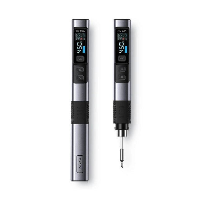
The FNIRSI HS-02A is an improved version of the HS-01 soldering iron with a better grip and a shorter tip for more comfort and precision during use. It features a larger 0.96-inch IPS HD color display that allows for better visibility of settings and status. With an output power of 100 W, the HS-02A heats up quickly and reaches operating temperature in about 2 seconds. The temperature is adjustable in a range of 100-450°C (212-842°F) to meet different soldering requirements.
Features
Temperature: 100-450°C (212-842°F)
Accurate temperature adjusting and control
Fast heating
CNC Metal Shell
Adaptive Power
100 W High Power
Protocols: PD, QC
Specifications
Temperature Range
100-450°C (212-842°F)
Working Voltage
9-20 V
Display
0.96" IPS HD Color Screen
Power Supply
USB-C
Fast Charging Protocols
PD / QC
Power
100 W (max)
Dimensions
180 x 20 mm
Weight
61 g
Included
1x FNRISI HS-02A Smart soldering iron
6x Soldering iron tips (HS02A-KU, HS02A-K, HS02A-JS, HS02A-I, HS02A-C2, HS02A-B)
1x Mini soldering iron stand
1x Manual
Downloads
Manual
Firmware V1.7
The Andonstar ADSM302 is a versatile digital microscope with an integrated 5-inch LCD display and HDMI output for crystal-clear views in Full HD (1080p). With a 3-megapixel sensor, up to ~560x magnification, and two adjustable LED lights, it reveals the finest details – ideal for PCB inspections, soldering work, jewelry or insect analysis.
Features
5" adjustable LCD monitor with adjustable tilt angle
High resolution video & photo capture
Wide table with comfortable headroom
Heavy-weight stable metal stand
Tall lifting stand (26 cm)
Smooth adjustment wheels for focus and height
Buttons on the monitor + remote control
AV, USB, HDMI outputs
SD card storage <32 GB
Specifications
Image sensor
3 Megapixels HD Sensor
Video output
1080p Full HD (via HDMI)720p (via PC)
Video format
Real time play via HDMI w/o recordingMJPEG recording via PC/Mac Software
Magnification
Up to 560 times (HDMI monitor 22")
Photo resolution
12M (see pixel formats in following table)
Photo format
JPEG
Focus range
5 to 22 cm
Frame rate
Up to 30 f/s under 600 Lux Brightness
Video-output interface
HDMI/AV
Storage
microSD card, up to 32 GB
PC support
Windows XP/7/8/10PC software with measurementMacOS successfully tested under OSX with OBSsee video below
Power source
5 V DC
Light source
2x LED with the stand
Screen size
5 inch (12.7 cm)
Stand size
20 x 12 x 26.5 cm
Resolution
Captured Photos
4032 x 3024
3648 x 2736
3264 x 2448
2592 x 1944
2048 x 1536
640 x 480
1920 x 1080
1280 x 960
1280 x 720*
Videos
1920 x 1080
640 x 480*
* (USB with software)
Included
1x Andonstar ADSM302 digital microscope
1x Metal stand with 2 LEDs
1x USB cable
1x HDMI cable
1x Adapter
1x AI remote
1x Instructions
Downloads
Manual
Software
For a limited time, the Joy-Pi Advanced is available in a great-value bundle with a Raspberry Pi 4 (8 GB)!
The Joy-Pi Advanced is a compact and powerful device that allows you to realize your projects quickly and easily. Whether you already have a lot of experience, or next to none, the Joy-Pi Advanced lets you unleash your creativity. Thanks to its compatibility with a wide range of platforms, including Raspberry Pi, Raspberry Pi Pico, Arduino Nano, BBC micro:bit, and NodeMCU ESP32, you can easily and quickly access your preferred platform.
In addition, the Joy-Pi Advanced features more than 30 stations, lessons, and modules, giving you an unlimited variety of ways to get your projects done. With the self-developed learning center, you can not only improve your skills but also create new projects. The learning center offers a wealth of information and tutorials that will guide you step by step through your projects.
Joy-Pi Advanced is characterized in particular by its intelligent switch units, which allow an extended use of the available pins. A total of three switch units are integrated, each equipped with 12 individual switches that provide precise control of the connected sensors and modules. This system solves the well-known problem of limited pin count that occurs with conventional microcontrollers. The switch units allow you to operate a large number of sensors and modules in parallel by switching them on and off individually. This simulates multiple pin assignment, allowing you to exploit the full power of your projects without compromising functionality.
By combining innovative adapter boards and the micro:bit slot, you can achieve seamless compatibility with a wide range of microcontrollers such as Raspberry Pi Pico, NodeMCU ESP32, micro:mit and Arduino Nano. The specially developed adapter boards are designed to perfectly match the respective microcontroller. By plugging the microcontroller onto the appropriate adapter board and then plugging it into the micro:bit slot, the Joy-Pi Advanced quickly and easily becomes compatible with the different microcontrollers. This allows seamless integration of your preferred platform and the ability to combine the strengths of the different microcontrollers in your projects. This way, you can fully focus on your creative projects without worrying about the compatibility of different microcontrollers. The Joy-Pi Advanced simplifies the development process and gives you the possibility to design your projects flexibly and individually.
Features
Highly integrated development platform & learning center
Fast, easy & wireless combination of various sensors & actuators
Installation option for Raspberry Pi 4
Compatible with various microcontrollers
Self-developed, didactic learning platform for Raspberry Pi & Windows
Specifications
Compatible to
Raspberry Pi 4, Arduino Nano, NodeMCU ESP32, BBC micro:bit, Raspberry Pi Pico
Installed sensors, actuators & components
39
Learning platform
Over 40 entries in the know-ledge database, 10 projects, 10 learning tasks, 14 visions
Displays
7-segment display, 16x2 display, 1.8“ TFT display, 0.96" OLED display, 8x8 RGB matrix
Sensors
DS18B20, shock sensor, hall sensor, barometer, sound sensor, gyroscope, PIR sensor, Light barrier, NTC, Light sensor, 6x touch sensor, color sensor, ultrasonic distance sensor, DHT11 temperature & humidity sensor
Control
Joystick, 5x switches, potentiometer, rotary encoder, 4x4 button matrix, relays, PWM fan
Motors
Servo interface, Stepper motor interface, Vibration motor
Measuring & conversion modules
Analog-Digital Converter, Level converter, voltmeter, Variable voltage supply
Other components
RTC real time clock, buzzer, EEPROM memory, infrared receiver, breadboard, RFID reader
Adapter boards
Adapter for NodeMCU ESP32, Arduino Nano & Raspberry Pi Pico, Board connectors for Raspberry Pi & External Boards
Electronic components
Infrared remote control, RFID chip, RFID card, 6x alligator clips, microSD card reader, servo motor, stepper motor, 32 GB microSD card
Components
40x resistors, 3x green LEDs, 3x yellow LEDs, 3x red LEDs, 1x transistor, 5x buttons, 1x potentiometer, 2x capacitors
Other accessories
Screw assortment, screwdriver, accessory storage bag, power supply & power cable, servo mount
Power supply
Built-in power supply: 36 W, 12 V, 3 A Case connector: Small device plug C8
Voltage outputs
12 V, 5 V, 3.3 V, Variable voltage output (2-11 V)
Data buses & signal outputs
I²C, SPI, Analog to digital converter
Battery (RTC)
CR2032
Dimensions
327 x 200 x 52 mm
Included
Raspberry Pi 4 (8 GB RAM)
Downloads
Joy-Pi website
Datasheet
Manual
This clear acrylic case is the official case for the HackRF One/Pro board. It can replace the standard black plastic case of the HackRF One/Pro.
Assembly Instructions
Use a guitar pick or spudger to extract the HackRF One/Pro circuit board from the black plastic case.
Insert one long screw into each corner of the bottom acrylic panel. Secure each long screw with a short (5 mm) spacer on the opposite side of the panel.
Place the HackRF One/Pro circuit board (facing up) on top of the bottom panel, fitting the ends of the long screws through the corner mounting holes of the circuit board.
Secure the circuit board with one long (6 mm) spacer in each corner.
Place the top acrylic panel on top of the circuit board, aligning the cutouts with the circuit board’s expansion headers.
Secure each corner with a short screw.
Note: Do not overtighten! Hand-tighten only at every step.
The OWON XDM1241 is a fast, high-precision digital True RMS benchtop multimeter with a high-resolution 3.5-inch LCD and 50,000 counts. Its DC voltage accuracy is up to 0.05% and it can measure up to 65 values per second.
Features
3.5' high-resolution LCD (480x320 pixels)
55000 counts, DC voltage accuracy up to 0.05%
Up to 65 readings per second
Dual line display supported
Trend analysis accessible in chart mode
AC True RMS measurements (bandwidth: 20 Hz – 1 kHz)
SCPI support: Remote control the multimeter through PC software via USB port
Data record function, you can record the measured data into internal memory, and then read and process the recorded data with your computer.
Specifications
Measurement Range
Resolution
Accuracy
DC Voltage
50.000 mV
0.001 mV
0.1% +10
500.00 mV
0.01 mV
0.05% +5
5.0000 V
0.0001 V
0.05% +5
50.000 V
0.001 V
0.05% +5
500.00 V
0.01 V
0.1% +5
1000.0 V
0.1 V
0.1% +10
AC Voltage
500 mV~750 V
20 Hz~45 Hz
1% +30
45 Hz~65 Hz
0.5% +30
65 Hz~1 KHz
0.7% +30
DC Current
500 uA
0.01 uA
0.15% +20
5000 uA
0.1 uA
0.15% +10
50 mA
0.001 mA
0.15% +20
500 mA
0.01 mA
0.15% +10
5 A
0.0001 A
0.5% +10
10 A
0.001 A
0.5% +10
AC Current
500 uA~500 mA
20 Hz~1 KHz
0.5% +20
5 A-10 A
1.5% +20
Resistance
500 Ω
0.01 Ω
0.15% +10
5 KΩ
0.0001 KΩ
0.15% +5
50 KΩ
0.001 KΩ
0.15% +5
500 KΩ
0.01 KΩ
0.15% +5
5 MΩ
0.0001 MΩ
0.3% +5
50 MΩ
0.001 MΩ
1% +10
Frequency
10.000 Hz~60 MHz
/
±(0.2% +10)
Capacitance
50 nF~500 uF
/
2.5% +10
5 mF~50 mF
5% +10
Diode
3.0000 V
0.0001 V
/
Continuity
1000 Ω
0.1 Ω
Adjustable threshold
Temperature
K type, PT100
Max Display
55,000 counts
Data-logging Function
Logging Duration
15ms~9999.999s
Logging Length
1,000 points
Display
3.5' TFT LCD (480x320 pixels)
Power supply
Lithium battery via USB-C or 5 V DC input
Dimensions
235 x 88 x 65 mm
Weight
approx. 0.5 kg
Included
1x OWON XDM1241 Multimeter
2x Test leads
1x USB cable
1x USB to DC cord
1x Manual
Downloads
Programming Manual
PC Software
This all-in-one Raspberry Pi 5 Desktop Kit contains all official parts and allows you to get started with the Raspberry Pi 5 quickly and easily.
Included
Official 27 W Power Supply for Raspberry Pi 5 (EU, white)
Official Case for Raspberry Pi 5 (white/red)
Official Raspberry Pi Keyboard (US)
Official Raspberry Pi Mouse
2x micro HDMI to Standard HDMI cable (A/M) 1 m
microSD Card pre-installed with Raspberry Pi OS (32 GB)
The Official Raspberry Pi Beginner's Guide (5th Edition)
Not included
Raspberry Pi 5
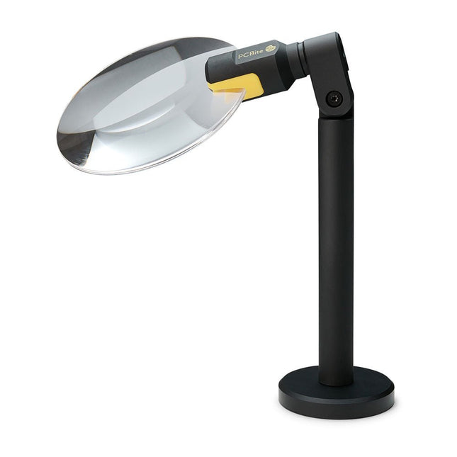
The PCBite Magnifier (premium build quality made from CNC machined aluminum) enlarges your target and makes it easier to see during soldering, inspection and measurements. Especially useful when placing PCBite hands free probes on fine pitch SMD components during measurements.
3x magnification edgeless lens for increased visibility of the work surface and AR coating (anti-reflection) to reduce reflections from nearby light sources.
Optimized design, magnification and focal point for use together with the PCBite PCB holders and baseplates included in all PCBite kits. Can also be used handheld but not standalone without a metal surface as base.
At the bottom of the magnifier foot there is a strong magnet perfectly balanced in strength. A low friction bottom cap protects the magnet and the baseplate to make the magnifier easy to slide when repositioning or removing the magnifier from the baseplate.
Friction based adjustment of lens tilt and rotate positions takes away the need for annoying and complicated set screws.
Raspberry Pi 5 provides two four-lane MIPI connectors, each of which can support either a camera or a display. These connectors use the same 22-way, 0.5 mm-pitch “mini” FPC format as the Compute Module Development Kit, and require adapter cables to connect to the 15-way, 1 mm-pitch “standard” format connectors on current Raspbery Pi camera and display products.These mini-to-standard adapter cables for cameras and displays (note that a camera cable should not be used with a display, and vice versa) are available in 200 mm, 300 mm and 500 mm lengths.
The HDS242 is a portable 2-in-1 multifunctional tester, which can be used as a 2-ch oscilloscope and multimeter. It features a high-contrast 3.5-inch color display suitable for outdoor facility maintenance, rapid on-site measurement, automobile maintenance, power detection. etc.
Features
Oscilloscope + Multimeter
3.5-inch high-resolution, high-contrast color LCD display – suitable for outdoor use
18650 lithium battery – can work continuously for up to 6 hours
USB-C interface – support power bank and PC connection
Self-calibration function
SCPI supported – facilitate secondary development
Specifications
Oscilloscope
Bandwidth
40 MHz
Channels
2-ch Oscilloscope
Sample Rate
250 MSa/s
Acquisition Model
Normal, Peak detect
Record Length
8K
Display
3.5-inch LCD
Waveform Refresh Rate
10,000 wfrms/s
Input Coupling
DC, AC, and Ground
Input Impedance
1 MΩ ±2%, in parallel with 16pF ±10pF
Probe Attenuation Factors
1X, 10X, 100X, 1000X, 10000X
Max. Input Voltage
400 V (DC+AC, PK-PK, 1MΩ input impedance) (10:1 probe attenuation)
Bandwidth Limit (typical)
20 MHz
Horizontal Scale
5ns/div - 1000s/div, step by 1 - 2 - 52ns/div - 1000s/div, step by 1 - 2 - 55ns/div - 1000s/div, step by 1 - 2 - 52ns/div - 1000s/div, step by 1 - 2 - 5
Vertical Sensitivity
10mV/div - 10V/div
Vertical Resolution
8 bits
Trigger Type
Edge
Trigger Modes
Auto, Normal, single
Automatic Measurement
Frequency, Period, Amplitude, Max, Min, Mean, PK-PK
Cursor Measurement
ΔV, ΔT, ΔT & ΔV between cursors
Multimeter
Max. Resolution
20,000 counts
Testing Mode
Voltage, Current, Resistance, Capacitance, Diode, and Continuity test
Input Impedance
10 MΩ
Max Input Voltage
AC: 750 V | DC: 1000 V
Max Input Current
DC: 10 A | AC: 10 A
Diode
0-2 V
Other
Connectivity
USB Type-C
Dimensions
198 x 96 x 38 mm (7.68 x 3.74 x 1.5')
Weight
600 g (without batteries)
Included
1x OWON HDS242 Oscilloscope
1x Soft Bag
1x Probe
1x Power Cord
1x Probe Adjust
1x USB Cable
1x Power Adapter
1x Pair of Multimeter Probe Leads (red one and black one)
1x Pair of Oscilloscope Probe Leads (BNC to Alligator Clip)
1x User Manual (English)
Downloads
User Manual
SCPI Protocol
Quick Guide
PC Software
Features
4 1/2 bit resolution (20000 Counts)
Data Logger
Multimeter
Thermometer
True RMS test supported
BLE 4.0 wireless transmission, more stable,less power consumption
Build-in offline record function
Chart and Diagram mode helps to analyze the data tendency
Flashlight function lightens the darkness
Support NCV non-contact voltage sense
Widely supported on Android, iOS, Windows
Included
OWON OW18E Multimeter
Quick Guide
Multimeter Lead
K-type Thermocouple
Bolt Driver
App Download
The Bluetooth function of this multimeter is compatible with Android-app version 1.5.8.0 or newer.
Use the QR code in the box or go to http://files.owon.com.cn/bluetooth.
Contents Basic principles A connector is an electromechanical system that provides a separable connection between two subsystems of an electronic device without an unacceptable effect on the performance of the device. It will be shown that there are a lot of complex parameters to handle properly to make this statement true. Design / Selection / Assembly This chapter provides an overview of design and material requirements for contact finishes, contact springs and connector housings as well as the major degradation mechanisms for these connector components. To complete this chapter, material selection criteria for each will also be reviewed. Additionally the Level of Interconnection (LOI) was integrated into this chapter as it addresses, where the connector is used within an electronic system and therefore influences the requirements and durability of the connector depending on its use. Applications This chapter is heading to the practical work and shows how customers use connectors in their applications to offer some possibilities and to ease your daily work. Additionally it contains some special topics like tin-whisker or impedance of ZIF cable to offer you extended background knowledge.
This hands-on bundle lets you build real Edge AI applications with the Raspberry Pi
Raspberry Pi AI HAT+ (13 TOPS)
The Raspberry Pi AI HAT+ (13 TOPS) is an expansion board designed for the Raspberry Pi 5, featuring an integrated Hailo AI accelerator. This add-on offers a cost-effective, efficient, and accessible approach to incorporating high-performance AI capabilities, with applications spanning process control, security, home automation, and robotics.
The AI HAT+ connects via the Raspberry Pi 5’s PCIe Gen3 interface. When the Raspberry Pi 5 is running a current version of the Raspberry Pi OS, it automatically detects the onboard Hailo accelerator, making the neural processing unit (NPU) available for AI tasks. Additionally, the rpicam-apps camera applications included in Raspberry Pi OS seamlessly support the AI module, automatically using the NPU for compatible post-processing functions.
Raspberry Pi Camera Module 3
Raspberry Pi Camera Module 3 is a compact camera from Raspberry Pi. It offers an IMX708 12-megapixel sensor with HDR, and features phase detection autofocus. Camera Module 3 is available in standard and wide-angle variants, both of which are available with or without an infrared cut filter.
Camera Module 3 can be used to take full HD video as well as stills photographs, and features an HDR mode up to 3 megapixels. Its operation is fully supported by the libcamera library, including Camera Module 3’s rapid autofocus feature: this makes it easy for beginners to use, while offering plenty for advanced users. Camera Module 3 is compatible with all Raspberry Pi computers.
Book: Edge AI Made Practical – AI Projects for the Raspberry Pi with the AI HAT+
Edge AI is transforming everyday devices by putting intelligence where it matters most: directly inside the hardware. With on-device inference, a camera can recognize a visitor instantly, a phone can translate speech without streaming audio to the cloud, and a wearable can detect anomalies in real time—fast, private, and reliable even when the network disappears.
This book is your practical guide to building exactly those kinds of systems with the Raspberry Pi AI HAT+ and the Hailo-8L accelerator. You’ll start with clear foundations: core AI and machine-learning concepts, how neural networks work, and what truly distinguishes Edge AI from cloud AI—plus an honest look at ethical considerations and future impacts.
This bundle contains:
Book: Edge AI Made Practical
Raspberry Pi AI HAT+ (13 TOPS)
Raspberry Pi Camera Module 3
Active Cooler for Raspberry Pi 5
FPC Display Cable for Raspberry Pi 5 (300 mm)
Elektor Component Kit
40-pin GPIO Header
Traffic Light Module
LED red 5 V with built-in resistor
LED yellow 5 V with built-in resistor
LED green 5 V with built-in resistor
LED blue 5 V with built-in resistor
Breadboard (400 Tie-points)
10 Dupont wires male-female
DHT22 sensor module
Servo motor
Required
Raspberry Pi 5
The Raspberry Pi Monitor is a 15.6-inch Full HD computer display. User-friendly, versatile, compact and affordable, it is the perfect desktop display companion for both Raspberry Pi computers and other devices.
With built-in audio via two front-facing speakers, and VESA and screw mounting options as well as an integrated angle-adjustable stand, the Raspberry Pi Monitor is ideal for desktop use or for integration into projects and systems. It can be powered directly from a Raspberry Pi, or by a separate power supply.
Features
15.6-inch full HD 1080p IPS display
Integrated angle-adjustable stand
Built-in audio via two front-facing speakers
Audio out via 3.5 mm jack
Full-size HDMI input
VESA and screw mounting options
Volume and brightness control buttons
USB-C power cable
Specifications
Display
Screen size: 15.6 inches, 16:9 ratio
Panel type: IPS LCD with anti-glare coating
Display resolution: 1920 x 1080
Color depth: 16.2M
Brightness (typical): 250 nits
Color gamut: 45%
Viewing angle: 80°
Power
1.5 A/5 V
Can be powered directly from a Raspberry Pi USB port (max 60% brightness, 50% volume) or by a separate power supply (max 100% brightness, 100% volume)
Connectivity
Standard HDMI port (1.4 compliant)
3.5 mm stereo headphone jack
USB-C (power in)
Audio
2x 1.2 W integrated speakers
Support for 44.1 kHz, 48 kHz, and 96 kHz sample rates
Downloads
Datasheet
PCBite is the complete solution handling your circuit board during the development phase. Powerful magnets together with a stainless base plate makes the system flexible, mobile and user friendly.
The holder can easily be repositioned to handle circuit boards of varying shape and sizes.
The probes are steady but yet flexible made for instant measurements or total hands-free operations together with your multimeter or prefered tool.
Included
4x PCBite holder
2x Banana to DuPont test wires red/black
2x SP10 probe with red/black probe head and pin tipped test needles
2x Extra crown tipped test needle
1x Set of yellow insulation washers
1x Large Baseplate (A4)
1x Microfiber cloth
Downloads
User Guide
The Elektor Arduino Nano MCCAB Training Board contains all the components (incl. Arduino Nano) required for the exercises in the "Microcontrollers Hands-on Course for Arduino Starters", such as light-emitting diodes, switches, pushbuttons, acoustic signal transmitters, etc. External sensors, motors or assemblies can also be queried or controlled with this microcontroller training system.
Specifications (Arduino Nano MCCAB Training Board)
Power Supply
Via the USB connection of the connected PC or an external power supply unit (not included)
Operating Voltage
+5 Vcc
Input Voltage
All inputs
0 V to +5 V
VX1 and VX2
+8 V to +12 V (only when using an external power supply)
Hardware periphery
LCD
2x16 characters
Potentiometer P1 & P2
JP3: selection of operating voltage of P1 & P2
Distributor
SV4: Distributor for the operating voltagesSV5, SV6: Distributor for the inputs/outputs of the microcontroller
Switches and buttons
RESET button on the Arduino Nano module 6x pushbutton switches K1 ... K6 6x slide switches S1 ... S6 JP2: Connection of the switches with the inputs of the microcontroller
Buzzer
Piezo buzzer Buzzer1 with jumper on JP6
Indicator lights
11 x LED: Status indicator for the inputs/outputs LED L on the Arduino Nano module, connected to GPIO D13 JP6: Connection of LEDs LD10 ... LD20 with GPIOs D2 ... D12
Serial interfacesSPI & I²C
JP4: Selection of the signal at pin X of the SPI connector SV12 SV9 to SV12: SPI interface (3.3 V/5 V) or I²C interface
Switching output for external devices
SV1, SV7: Switching output (maximum +24 V/160 mA, externally supplied) SV2: 2x13 pins for connection of external modules
3x3 LED matrix(9 red LEDs)
SV3: Columns of the 3x3 LED matrix (outputs D6 ... D8) JP1: Connection of the rows with the GPIOs D3 ... D5
Software
Library MCCABLib
Control of hardware components (switches, buttons, LEDs, 3x3 LED matrix, buzzer) on the MCCAB Training Board
Operating Temperature
Up to +40 °C
Dimensions
100 x 100 x 20 mm
Specifications (Arduino Nano)
Microcontroller
ATmega328P
Architecture
AVR
Operating Voltage
5 V
Flash Memory
32 KB, of which 2 KB used by bootloader
SRAM
2 KB
Clock Speed
16 MHz
Analog IN Pins
8
EEPROM
1 KB
DC Current per I/O Pins
40 mA on one I/O pin, total maximum 200 mA on all pins together
Input Voltage
7-12 V
Digital I/O Pins
22 (6 of which are PWM)
PWM Output
6
Power Consumption
19 mA
Dimensions
18 x 45 mm
Weight
7 g
Included
1x Elektor Arduino Nano Training Board MCCAB
1x Arduino Nano
Learn KiCad with Peter Dalmaris
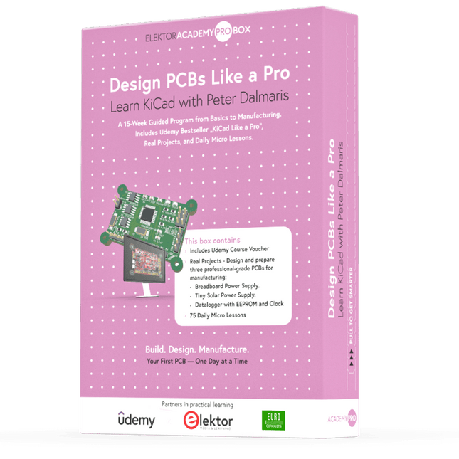
The Academy Pro Box "Design PCBs like a Pro" offers a complete, structured training programme in PCB design, combining online learning with practical application. Based on Peter Dalmaris’ KiCad course, the 15-week programme integrates video lessons, printed materials (2 books), and hands-on projects to ensure participants not only understand the theory but also develop the skills to apply it in practice.
Unlike standard courses, the Academy Pro Box provides a guided learning path with weekly milestones and physical components to design, test, and produce working PCBs. This approach supports a deeper learning experience and better knowledge retention.
The box is ideal for engineers, students, and professionals who want to develop practical PCB design expertise using open-source tools. With the added option to have their final project manufactured, participants complete the programme with real results – ready for use, testing, or further development.
Learn by doing
Build skills. Design real boards. Generate Gerbers. Place your first order. This isn’t just a course – it’s a complete project journey from idea to product.
You’ll walk away with:
Working knowledge of KiCad’s tools
Confidence designing your own PCBs
A fully manufacturable circuit board – made by you
What's inside the Box (Course)?
Both volumes of "KiCad Like a Pro" (valued at €105)
Vol 1: Fundamentals and Projects
Vol 2: Advanced Projects and Recipes
Coupon code to join the bestselling KiCad 9 online course by Peter Dalmaris on Udemy, featuring 20+ hours of video training. You'll complete three full design projects:
Breadboard Power Supply
Tiny Solar Power Supply
Datalogger with EEPROM and Clock
Voucher from Eurocircuits for the production of PCBs (worth €85 excl. VAT)
Learning Material (of this Box/Course)
15-Week Learning Program
▶ Click here to open
Week 1: Setup, Fundamentals, and First Steps in PCB Design
Week 2: Starting Your First PCB Project – Schematic Capture
Week 3: PCB Layout – From Netlist to Board Design
Week 4: Design Principles, Libraries, and Workflow
Week 5: Your First Real-World PCB Project
Week 6: Custom Libraries – Symbols, Footprints, and Workflow
Week 7: Advanced Tools – Net Classes, Rules, Zones, Routing
Week 8: Manufacturing Files, BOMs, and PCB Ordering
Week 9: Advanced Finishing Techniques – Graphics, Refinement, and Production Quality
Week 10: Tiny Solar Power Supply – From Schematic to Layout
Week 11: Tiny Solar Power Supply – PCB Layout and Production Prep
Week 12: ESP32 Clone Project – Schematic Design and Layout Prep
Week 13: ESP32 Clone – PCB Layout and Manufacturing Prep
Week 14: Final Improvements and Advanced Features
Week 15: Productivity Tools, Simulation, and Automation
KiCad Course with 18 Lessons on Udemy (by Peter Dalmaris)
▶ Click here to open
Introduction
Getting started with PCB design
Getting started with KiCad
Project: A hands-on tour of KiCad (Schematic Design)
Project: A hands-on tour of KiCad (Layout)
Design principles and PCB terms
Design workflow and considerations
Fundamental KiCad how-to: Symbols and Eeschema
Fundamental KiCad how-to: Footprints and Pcbnew
Project: Design a simple breadboard power supply PCB
Project: Tiny Solar Power Supply
Project: MCU datalogger with build-in 512K EEPROM and clock
Recipes
KiCad 9 new features and improvements
Legacy (from previous versions of KiCad)
KiCad 7 update (Legacy)
(Legacy) Gettings started with KiCad
Bonus lecture
About the Author
Dr. Peter Dalmaris, PhD is an educator, an electrical engineer and Maker. Creator of online video courses on DIY electronics and author of several technical books. As a Chief Tech Explorer since 2013 at Tech Explorations, the company he founded in Sydney, Australia, Peter's mission is to explore technology and help educate the world.
What is Elektor Academy Pro?
Elektor Academy Pro delivers specialized learning solutions designed for professionals, engineering teams, and technical experts in the electronics and embedded systems industry. It enables individuals and organizations to expand their practical knowledge, enhance their skills, and stay ahead of the curve through high-quality resources and hands-on training tools.
From real-world projects and expert-led courses to in-depth technical insights, Elektor empowers engineers to tackle today’s electronics and embedded systems challenges. Our educational offerings include Academy Books, Pro Boxes, Webinars, Conferences, and industry-focused B2B magazines – all created with professional development in mind.
Whether you're an engineer, R&D specialist, or technical decision-maker, Elektor Academy Pro bridges the gap between theory and practice, helping you master emerging technologies and drive innovation within your organization.
The SEQURE T55 Smart Mini Temperature Adjustable Soldering Hot Plate is a compact and efficient tool designed for precise preheating and desoldering tasks. With its adjustable temperature range from 50°C to 280°C (122°F to 536°F), it is suitable for various applications, e.g. cell phone repair, PCB assembly, etc.
Features
Adjustable heating temperature range: 50°C to 280°C (122°F to 536°F)
Equipped with a heat-resistant ceramic temperature sensor, ensuring high-accuracy data measurement under continuous high temperatures.
Automatically stops heating after reaching the preset working time.
Supports PD, QC, and DC (max 25 V).
Intelligent temperature control algorithm for temperature compensation and power adjustment.
128 x 32 resolution OLED display with a built-in buzzer to indicate operating status.
°C/°F conversion
Specifications
Heating Area
55 x 55 mm
Working Temperature
50-280°C (122-536°F)
Max Voltage
25 V
Max Power
95 W
Recommend Voltage
19-25 V
PD Power Supply
PD 20 V ≥3A
Power Supply Modes
PD, QC, DC
Interface
USB-C
Display
128 x 32 OLED
Menu Languages
English, Russian, and Chinese
Dimensions
55 x 60 x 37 mm
Weight
92 g
Included
1x SEQURE T55 Smart Mini Soldering Hot Plate
1x PD 65 W Power Supply (EU)
1x Fast Charging Cable (100 W/5 A)
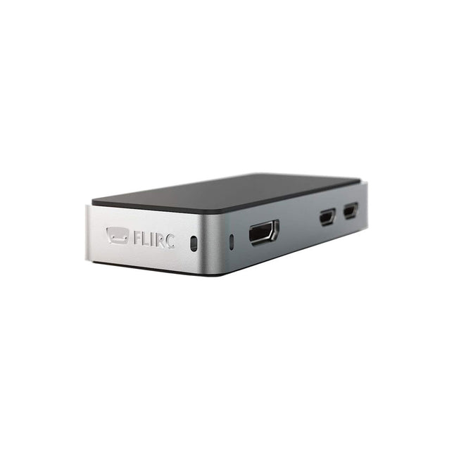
The FLIRC Raspberry Pi Zero Case is compatible with Raspberry Pi Zero W and the newer Raspberry Pi Zero 2 W.
The design of the FLIRC Zero Case is based on the original FLIRC case. As with the original, the aluminum housing serves as protection and, thanks to the contact point on the processor, as a passive cooler. Ideal for silent operation.
In addition to a normal cover that encloses and protects the Raspberry Pi Zero, there is a second cover that allows access to the GPIO pins through a small opening.
The ZD-8962B soldering station features an adjustable temperature range of 160°C to 480°C with an output power of 70 W. Equipped with an integrated heating element in the soldering tip, the station reaches the desired operating temperature in just 8 seconds.
A large digital display provides real-time monitoring, showing both the preset target and the actual temperature of the iron for precision control. Additionally, the station is ESD-safe, ensuring sensitive electronic components are fully protected from electrostatic discharge during use.
Specifications
Power
70 W
Input voltage
220-240 V AC/50 Hz
Output voltage
20 V
Temperature range
160°C – 480°C (320°F – 896°F)
Heating time
~8 s
Display
Large, two-line LED display for showing target and actual temperature
Special features
ESD protection, Sleep mode/energy-saving function, Switch between °C and °F
Included
ZD-8962B Soldering station unit
Soldering iron
Soldering tip N12-1
Soldering iron stand with copper brush and sponge
Soldering wire stand with lead-free soldering wire (10 g)
Power cable (EU)
Manual
The Siglent SDS1104X-E employs a new generation of SPO (Super Phosphor Oscilloscope) technology that provides excellent signal fidelity and performance. The system noise is also lower than similar products in the industry. It comes with a minimum vertical input range of 500 uV/div, an innovative digital trigger system with high sensitivity and low jitter, and a waveform capture rate of 400,000 frames/sec (sequence mode).
The SDS1104X-E also employs a 256-level intensity grading display function and a color temperature display mode not found in other models in this class. SIGLENT’s latest oscilloscopes offering supports multiple powerful triggering modes including serial bus triggering. Serial decoding is free and includes IIC, SPI, UART, CAN, and LIN. History waveform recording and sequential triggering enable extended waveform recording and analysis. Another powerful addition is the new 1 Mpt FFT math function that gives the SDS1104X-E very high frequency resolution when observing signal spectra.
Features
Intelligent trigger: Edge, Slope, Pulse Width, Window, Runt, Interval, Timeout (Dropout), and Pattern
Free Serial bus triggering and decoding:IIC, SPI, UART, RS232, CAN, and LIN
Video triggers and supports HDTV
Low background noise and 500 μV / div to 10 V / div voltage scales
10 types of one-button shortcuts, supports Auto Setup, Default, Cursors, Measure, Roll, History, Display/Persist, Clear Sweep, Zoom and Print
Segmented acquisition (Sequence) mode, dividing the maximum record length into multiple segments (up to 80,000), according to trigger conditions set by the user, with a very small dead time segment to capture the qualifying event.
History waveform record (History) function, the maximum recorded waveform length is 80,000 frames
Automatic measurement function on 38 parameters, supports Statistics, Gating measurement, Math measurement, History measurement and Ref measurement
1 Mpts FFT
True measurement and math can use all 14 Mpts of memory
Preset key can be customized for user settings or factory “defaults”
Security Erase mode
Highspeed hardware based Pass/ Fail function
Large 7-inch TFT-LCD display with 800 * 480 resolution
Multiple interface types: USB Host, USB Device (USB-TMC), LAN (VXI-11), Pass / Fail, Trigger Out
Supports SCPI remote control commands
Multi-language display and embedded help
Browser control/onboard webpage for software free monitoring (4 channel models only)
Included
1x Siglent SDS1104X-E Oscilloscope
4x 100 MHz probes
1x Guarantee Card
1x Power Cord
1x USB Cable
1x Quick Start Guide
Downloads
Datasheet
Manual
Programming Guide
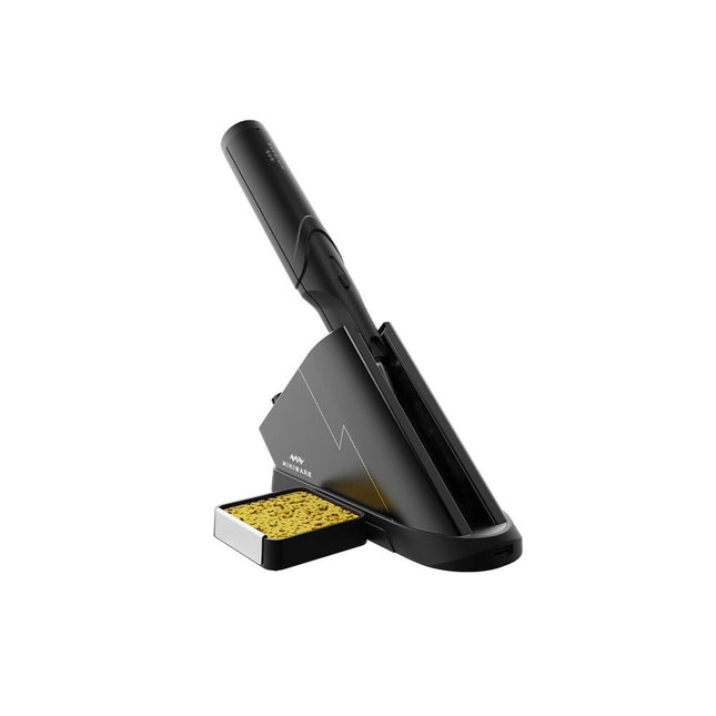
The Miniware Cordless Soldering Station TS1C (with integrated OLED screen and Bluetooth) is an intelligent soldering tool that heats up to 400°C in less than 20 seconds. Thanks to the built-in battery, the wireless soldering pen sits comfortably in the hand and is easy to use.
Features
New high-efficiency supercapacitor energy storage technology, 10,000-level charge and discharge times
Seperate design + true wireless, enjoy wireless soldering experience
BLE4.2 Bluetooth communication technology to realize remote control and setting
Standard PD2 20 V 45 W max power input, up to 36 W soldering power, can continuously solder more than 180 solder joints (0805) with a single full charge
Control station preheating to improve heating efficiency
3 expansion slots for accessories
Control Station
Standard PD2 20 V 45 W max power input, over current safety protection
128x64 pixel OLED screen, display soldering pen status in real time
Control station preheating, improve heating efficiency
Remote control and setting: temperature regulating, menu setting, viewing device info and status, etc.
Work as soldering stand and charging station
3 expansion slots for multiple expandable accessories like sponge slot
Soldering Pen
Built-in 750F high-efficiency energy storage supercapacitor, can be charged via control station (or via its USB Type-C interface in emergency cases)
36 W maximum heating power, can solder more than 180 solder joints (0805) continuously under a single full charge
Compatible with Miniware 3.5 mm audio interface soldering tips (TS80/80P soldering tip series)
Boost mode (holding the button on the pen)
Included
TS1C Soldering pen
TS1C Control station
Soldering tip (TS-B02)
Silicone cable
Sponge slot incl. sponge
Manual
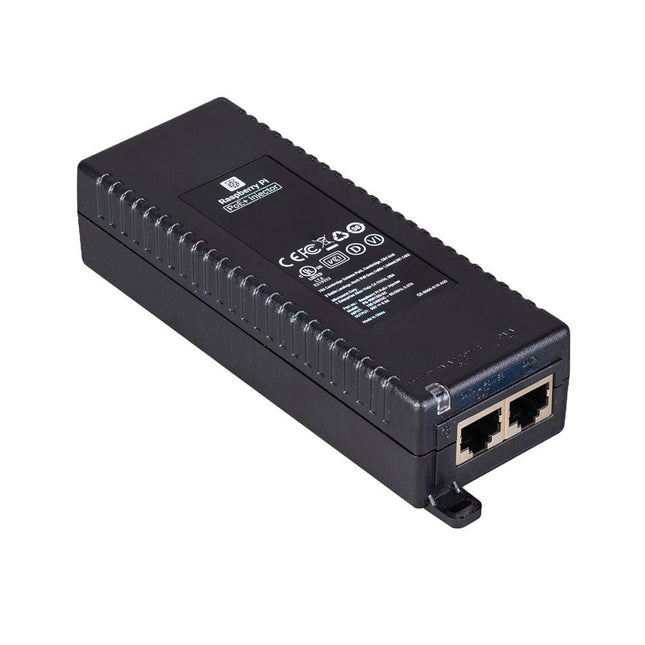
The Raspberry Pi PoE+ Injector adds Power-over-Ethernet (PoE) functionality to a single port of a non-PoE Ethernet switch, delivering both power and data through one Ethernet cable. It provides a plug-and-play, cost-effective solution for incrementally introducing PoE capability into existing Ethernet networks.
The PoE+ Injector is a single-port, 30 W device suitable for powering equipment compliant with IEEE 802.3af and 802.3at standards, including all generations of Raspberry Pi PoE HATs. It supports network pass-through speeds of 10/100/1000 Mbps.
Note: A separate IEC mains cable is required for operation (not included).
Specifications
Data rate
10/100/1000 Mbps
Input voltage
100 to 240 V AC
Output power
30 W
Power output on pins
4/5 (+), 7/8 (–)
Nominal output voltage
55 V DC
Data connectors
Shielded RJ-45, EIA 568A and 568B
Power connector
IEC c13 mains power input (not included)
Storage humidity
Maximum 95%, non-condensing
Operating altitude
–300 m to 3000 m
Operating ambient temperature
10°C to +50°C
Dimensions
159 x 51.8 x 33.5 mm
Downloads
Datasheet