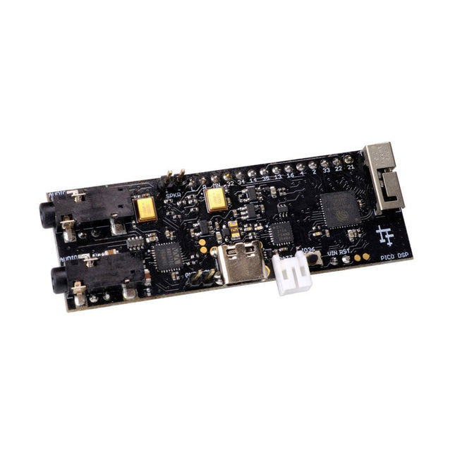
PÚCA DSP is an open-source, Arduino-compatible ESP32 development board for audio and digital signal processing (DSP) applications with expansive audio-processing features. It provides audio inputs, audio outputs, a low-noise microphone array, an integrated test-speaker option, additional memory, battery-charge management, and ESD protection all on a small, breadboard-friendly PCB.
Synthesizers, Installations, Voice UI, and More
PÚCA DSP can be used for a wide range of DSP applications, including but not limited to those in the fields of music, art, creative technology, and adaptive technology. Music-related examples include digital-music synthesis, mobile recording, Bluetooth speakers, wireless line-level directional microphones, and the design of smart musical instruments. Art-related examples include acoustic sensor networks, sound-art installations, and Internet-radio applications. Examples related to creative and adaptive technology include voice user interface (VUI) design and Web audio for the Internet of Sounds.
Compact, Integrated Design
PÚCA DSP was designed for portability. When used with an external 3.7 V rechargeable battery, it can be deployed almost anywhere or integrated into just about any device, instrument, or installation. Its design emerged from months of experimentation with various ESP32 development boards, DAC breakout boards, ADC breakout boards, Microphone breakout boards, and audio-connector breakout boards, and – despite its diminutive size – it manages to provide all of that functionality in a single board. And it dos so without compromising signal quality.
Specifications
Processor & Memory
Espressif ESP32 Pico D4 Processor
32-bit dual core 80 MHz / 160 MHz / 240 MHz
4 MB SPI Flash with 8 MB additional PSRAM (Original Edition)
Wireless 2.4 GHz Wi-Fi 802.11b/g/n
Bluetooth BLE 4.2
3D Antenna
Audio
Wolfson WM8978 Stereo Audio Codec
Audio Line In on 3.5 mm stereo onnector
Audio Headphone / Line Out on 3.5 mm stereo connector
Stereo Aux Line In, Audio Mono Out routed to GPIO Header
2x Knowles SPM0687LR5H-1 MEMS Microphones
ESD protection on all audio inputs and outputs
Support for 8, 11.025, 12, 16, 22.05, 24, 32, 44.1 and 48 kHz sample rates
1 W Speaker Driver, routed to GPIO Header
DAC SNR 98 dB, THD -84 dB (‘A’ weighted @ 48 kHz)
ADC SNR 95 dB, THD -84 dB (‘A’ weighted @ 48 kHz)
Line input impedance: 1 MOhm
Line output impedance: 33 Ohm
Form Factor and Connectivity
Breadboard friendly
70 x 24 mm
11x GPIO pins broken out to 2.54 mm pitch header, with access to both ESP32 ADC channels, JTAG and capacitive touch pins
USB 2.0 over USB Type C connector
Power
3.7/4.2 V Lithium Polymer Rechargeable Battery, USB or external 5 V DC power source
ESP32 and Audio Codec can be placed into low power modes under software control
Battery voltage level detection
ESD protection on USB data bus
Downloads
GitHub
Datasheet
Links
Crowd Supply Campaign (includes FAQs)
Hardware Overview
Programming the Board
The Audio Codec
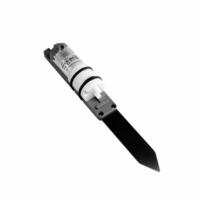
The M5Stack Watering Unit integrates water pump and measuring plates for soil moisture detection and pump water control. It can be used for intelligent plant breeding scenarios and can easily achieve humidity detection and Irrigation control. The measurement electrode plate uses the capacitive design, which can effectively avoid the corrosion problem of the electrode plate in actual use compared with the resistive electrode plate.
Features
Capacitive measuring plate (corrosion resistant)
Integrated 5 W power water pump
LEGO compatible holes
Applications
Plant cultivation
Soil moisture detection
Smart irrigation
Included
1x Watering Unit
2x Suction pipe
1x HY2.0-4P cable
Pump power
5 W
Weight
78 g
Dimensions
192.5 x 24 x 33 mm
The SparkFun GPS-RTK2 raises the bar for high-precision GPS and is the latest in a line of powerful RTK boards featuring the ZED-F9P module from u-blox. The ZED-F9P is a top-of-the-line module for high accuracy GNSS and GPS location solutions, including RTK capable of 10 mm, three-dimensional accuracy. With this board, you will be able to know where your (or any object's) X, Y, and Z location is within roughly the width of your fingernail! The ZED-F9P is unique in that it is capable of both rover and base station operations. Utilizing our handy Qwiic system, no soldering is required to connect it to the rest of your system. However, we still have broken out 0.1"-spaced pins if you prefer to use a breadboard.
We've even included a rechargeable backup battery to keep the latest module configuration and satellite data available for up to two weeks. This battery helps 'warm-start' the module decreasing the time-to-first-fix dramatically. This module features a survey-in mode allowing the module to become a base station and produce RTCM 3.x correction data.
The number of configuration options of the ZED-F9P is incredible! Geofencing, variable I²C address, variable update rates, even the high precision RTK solution can be increased to 20 Hz. The GPS-RTK2 even has five communications ports which are all active simultaneously: USB-C (which enumerates as a COM port), UART1 (with 3.3 V TTL), UART2 for RTCM reception (with 3.3V TTL), I²C (via the two Qwiic connectors or broken out pins), and SPI.
Sparkfun has also written an extensive Arduino library for u-blox modules to easily read and control the GPS-RTK2 over the Qwiic Connect System. Leave NMEA behind! Start using a much lighter weight binary interface and give your microcontroller (and its one serial port) a break. The SparkFun Arduino library shows how to read latitude, longitude, even heading and speed over I²C without the need for constant serial polling.
Features
Concurrent reception of GPS, GLONASS, Galileo and BeiDou
Receives both L1C/A and L2C bands
Voltage: 5 V or 3.3 V, but all logic is 3.3 V
Current: 68 mA - 130 mA (varies with constellations and tracking state)
Time to First Fix: 25 s (cold), 2 s (hot)
Max Navigation Rate:
PVT (basic location over UBX binary protocol) - 25 Hz
RTK - 20 Hz
Raw - 25 Hz
Horizontal Position Accuracy:
2.5 m without RTK
0.010 m with RTK
Max Altitude: 50k m
Max Velocity: 500 m/s
2x Qwiic Connectors
Dimensions: 43.5 x 43.2 mm
Weight: 6.8 g
This polysilicon solar panel (18 V/10 W) provides stable performance with a high conversion efficiency of >20%. Specifications Solar cell type Polysilicon Output power tolerance ±3% Operating voltage 17.6 V Open circuit voltage 21.6 V Cell quantity 36 (4x9) Power 10 Wp (max) Conversation efficiency >20% Operating current 0.57 A Short circuit current 0.61 A Standard system voltage 1000 V (Max) Operating temperature -40°C ~ +85°C Pressure on panel 30 m/s (200 kg/sq.m) (Max) Cable Length 90 cm, DC plug, OD 3.5 mm ID 1.35 mm Frame material Anodic oxidation aluminum alloy Dimensions 340 x 232 x 17 mm Weight 0.935 kg
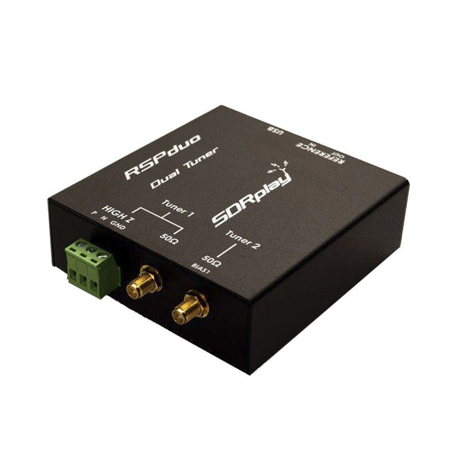
The SDRplay RSPduo is a high performance dual-tuner 14-bit SDR receiver. Housed in a high quality steel enclosure, each tuner can operate individually anywhere between 1 kHz and 2 GHz with up to 10 MHz of bandwidth or both tuners can operate simultaneously anywhere between 1 kHz and 2 GHz with up to 2 MHz of bandwidth per tuner.
A high stability reference along with external clocking features makes this device ideally suited to industrial, scientific & educational applications.
Features
Dual tuner provides independent coverage from 1 kHz to 2 GHz using 2 antenna ports simultaneously
14-bit ADC silicon technology
Up to 10 MHz visible bandwidth (single tuner mode) or 2 slices of 2 MHz spectrum (dual tuner mode)
3 software-selectable antenna ports (2x 50Ω and 1x 1kΩ high impedance balanced/unbalanced input)
High impedance antenna port (1 kHz to 30 MHz) with selectable MW notch filter and choice of 2 pre-selection filters
Software selectable AM/FM and DAB broadcast band notch filters for the 2 SMA antenna (1 kHz to 2 GHz) antenna ports
External clock input and output enables easy synchronisation to multiple RSPs or external reference clock
Powers over the USB cable with a simple type B socket
11 high-selectivity, built in front-end preselection filters on both the 2 SMA antenna ports
Software selectable multi-level Low Noise Preamplifier
Bias-T power supply for powering antenna-mounted LNA
Enclosed in a rugged black painted steel case.
SDRuno – World Class SDR software for Windows
Documented API for new apps development
Specifications
Frequency Range
1 kHz – 2 GHz
Antenna Connector
SMA
Antenna Impedance
50 Ohms
Current Consumption (Typical)
Single Tuner Mode: 180 mA (excl. Bias-T)Dual Tuner Mode: 280 mA (excl. Bias-T)
USB Connector
USB-B
Maximum Input Power
+0 dBm Continuous+10 dBm Short Duration
ADC Sample Rates
2-10.66 MSPS
ADC Number of Bits
14 bit 2-6.048 MSPS12 bit 6.048-8.064 MSPS10 bit 8.064-9.216 MSPS8 bit >9.216 MSPS
Bias-T
4.7 V100 mA guaranteed
Reference
High Temperature Stability (0.5ppm) 24 MHz TCXO.Frequency error trimmable to 0.01ppm in field.
Operating Temperature Range
−10˚C to +60˚C
Dimensions
98 x 94 x 33 mm
Weight
315 g
Downloads
Datasheet
Detailed Technical Information
Software
RSPdx-R2 vs RSPduo
RSPdx-R2
RSPduo
Continuous coverage from 1 kHz to 2 GHz
✓
✓
Up to 10 MHz visible bandwidth
✓
✓
14-bit ADC silicon technology plus multiple high-performance input filters
✓
✓
Software selectable AM/FM & DAB broadcast band notch filters
✓
✓
4.7 V Bias-T for powering external remote antenna amplifier
✓
✓
Powers over the USB cable with a simple type B socket
✓
✓
50Ω SMA antenna input(s) for 1 kHz to 2 GHz operation (software selectable)
2
2
Additional software selectable Hi-Z input for up to 30 Mhz operation
✓
Additional software selectable 50Ω BNC input for up to 200 MHz operation
✓
Additional LF/VLF filter for below 500 kHz
✓
24 MHz reference clock input (+ output on RSPduo)
✓
✓
Dual tuners enabling reception on 2 totally independent 2 MHz ranges
✓
Dual tuners enabling diversity reception using SDRuno
✓
Rugged black painted steel case
✓
✓
Overall performance below 2 MHz for MW and LF
++
+
Multiple simultaneous applications
+
++
Performance in challenging fading conditions (*using diversity tuning)
+
*++
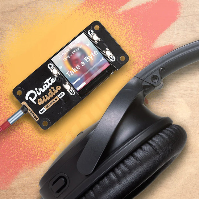
You could use Pirate Audio Headphone Amp to build a tidy, pocket-sized player for local audio files (MP3, FLAC, etc) or for streaming music from online services like Spotify. To help get you started, Pimoroni has built plugins for Mopidy that will let you display gorgeous album art, play/pause your tracks and adjust the volume. The DAC and headphone amp will give you crisp digital amplified audio through your wired headphones. Pirate Audio is a range of all-in-one audio boards for Raspberry Pi, with high-quality digital audio, beautifully-crisp IPS displays for album art, tactile buttons for playback control, and a custom Pirate Audio software and installer to make setting it all up a breeze. Features Amplified digital audio (24-bit / 192KHz) over I2S PAM8908 headphone amplifier chip Low-gain / high-gain switch (high-gain boosts by 12dB) PCM5100A DAC chip 3.5mm stereo jack 1.3' IPS colour LCD (240x240px) (ST7789 driver) Four tactile buttons Mini HAT-format board Fully-assembled Compatible with all 40-pin header Raspberry Pi models
Dimensions: 65x30.5x9.5mm Software The Pirate Audio software and installer installs the Python library for the LCD, configures the I2S audio and SPI, and then installs Mopidy and the custom Pirate Audio plugins to display album art and track info, and to use the buttons for playback control. Here's how to get started: Set an SD card up with the latest version of Raspberry Pi OS. Connect to Wi-Fi or a wired network. Open a terminal and type the following:git clone https://github.com/pimoroni/pirate-audiocd pirate-audio/mopidysudo ./install.sh
Reboot your Pi Downloads PAM8908 Datasheet PCM5100A Datasheet Pirate Audio software
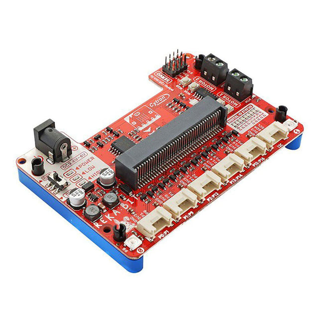
Program your REKA:BIT with Microsoft MakeCode Editor. Just add REKA:BIT MakeCode Extension and you’re good to go. If you’re a beginner, you can start with the block programming mode; simply drag, drop and snap the coding blocks together. For more advanced users, you can easily switch into JavaScript or Python mode on MakeCode Editor for text-based programming.
REKA:BIT possesses a lot of indicator LEDs to assist your coding and troubleshooting. It covers the IO pins connected to all six Grove ports and DC motor outputs from the co-processor. One is able to check his/her program and circuit connection easily by monitoring these LEDs.
Besides, REKA:BIT also has a power on/off indicator, undervoltage, and overvoltage LEDs built-in to give appropriate warnings should there be any problem with the power input.
REKA:BIT features a co-processor to handle multitasking more efficiently. Playing music while controlling up to 4x servo motors and 2x DC motors, animating micro:bit LED matrix, and even lighting up RGB LEDs in different colors, all at the same time, is not a problem for REKA:BIT.
Features
2x DC motor terminals
Built-in motor quick test buttons (no coding needed)
4x Servo motor ports
2x Neopixel RGB LEDs
6x Grove port (3.3 V)
3x Analog Input / Digital IO ports
2x Digital IO ports
1x I²C Interface
DC jack for power input (3.6-6 V DC)
ON/OFF switch
Power on indicator
Undervoltage (LOW) indicator & protection
Over-voltage (HIGH) indicator & protection
Dimensions: 10.4 x 72 x 15 mm
Included
1x REKA:BIT expansion board
1x USB power and data cable
1x 4xAA battery holder
1x Mini screwdriver
3x Grove to female header cable
2x Building block 1x9 lift arm
4x Building block friction pin
Please note: micro:bit board not included
Add this board to a device and you'll be able to connect it to a WiFi network, using its secure ECC608 crypto chip accelerator. The Arduino Uno WiFi is functionally the same as the Arduino Uno Rev3, but with the addition of WiFi/Bluetooth and some other enhancements. It incorporates the brand new ATmega4809 8-bit microcontroller from Microchip and has an onboard IMU (Inertial Measurement Unit) LSM6DS3TR.
The Wi-Fi Module is a self-contained SoC with an integrated TCP/IP protocol stack that can provide access to a Wi-Fi network, or act as an access point.
The Arduino Uno WiFi Rev2 has 14 digital input/output pins (5 that can be used as PWM outputs, 6 analog inputs), a USB connection, a power jack, an ICSP header, and a reset button. It contains everything needed to support the microcontroller. Simply connect it to a computer with a USB cable or power it with an AC adapter or battery to get started.
Specifications
Operating Voltage
5 V
Input Voltage
7 V - 12 V
Digital I/O
14
Analog Input Pins
6
Analog Input Pins
6
DC Current per I/O Pin
20 mA
DC Current for 3.3 V Pin
50 mA
Flash Memory
48 KB
SRAM
6.144 Bytes
EEPROM
256 Bytes
Clock Speed
16 MHz
Radio Module
u-blox NINA-W102
Secure Element
ATECC608A
Inertial Measurement Unit
LSM6DS3TR
LED_Builtin
25
Length
101.52 mm
Width
53.3 mm
Weight
37 g
The 555SE is an easy-to-build surface-mount soldering kit. It includes the circuit board, resistors, and transistors that make up the electrical circuit and printed assembly instructions. The kit also comes complete with the 'IC Leg' stand and 8 colour-coded thumbscrew terminal posts.
To build the 555SE, basic electronic soldering skill and tools are required, but no additional knowledge of electronics is presumed or required. You provide standard surface-mount soldering tools: a soldering iron, solder (wire or paste), small metal tweezers, as well as a Phillips head screwdriver.
The kit features relatively large surface mount components (1206 and SOT-23) and is a great first surface-mount soldering kit if you're just getting started. However, if you are experienced at surface mount soldering and have tools like a hot air rework station or other equipment, you're welcome to use them for assembling this kit.
Features
Anodized aluminium stand
8x 4-40 surface-mount threaded inserts
Stainless steel thumbscrews with colour-coded plastic caps (1 red, 1 black, 6 grey)
All materials (including the circuit board and stand) are RoHS compliant (lead-free)
Dimensions: 65 × 52 x 16 mm
Dimensions assembled: 65 × 78 × 20 mm
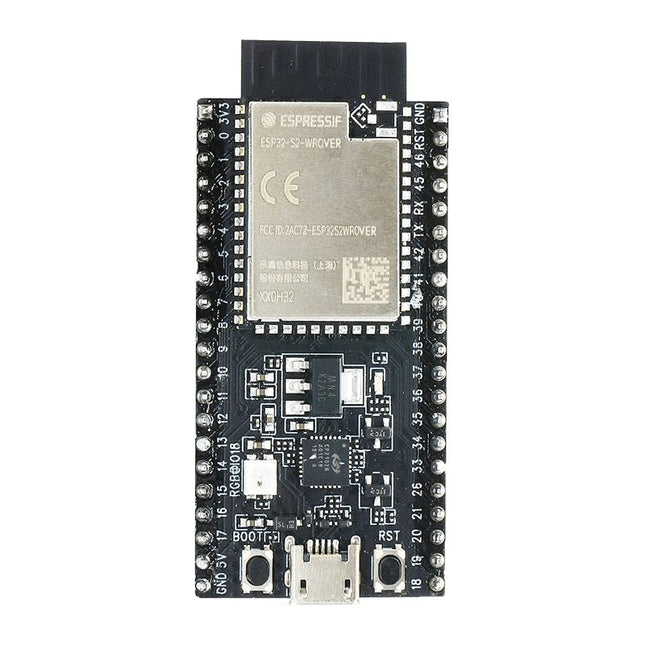
ESP32-S2-Saola-1R is a small-sized ESP32-S2 based development board. Most of the I/O pins are broken out to the pin headers on both sides for easy interfacing. Developers can either connect peripherals with jumper wires or mount ESP32-S2-Saola-1R on a breadboard.ESP32-S2-Saola-1R is equipped with the ESP32-S2-WROVER module, a powerful, generic Wi-Fi MCU module that has a rich set of peripherals. It is an ideal choice for a wide variety of application scenarios relating to Internet of Things (IoT), wearable electronics and smart home. The board a PCB antenna and features a 4 MB external SPI flash and an additional 2 MB SPI Pseudo static RAM (PSRAM).FeaturesMCU
ESP32-S2 embedded, Xtensa® single-core 32-bit LX7 microprocessor, up to 240 MHz
128 KB ROM
320 KB SRAM
16 KB SRAM in RTC
WiFi
802.11 b/g/n
Bit rate: 802.11n up to 150 Mbps
A-MPDU and A-MSDU aggregation
0.4 µs guard interval support
Center frequency range of operating channel: 2412 ~ 2484 MHz
Hardware
Interfaces: GPIO, SPI, LCD, UART, I²C, I²S, Camera interface, IR, pulse counter, LED PWM, TWAI (compatible with ISO 11898-1), USB OTG 1.1, ADC, DAC, touch sensor, temperature sensor
40 MHz crystal oscillator
4 MB SPI flash
Operating voltage/Power supply: 3.0 ~ 3.6 V
Operating temperature range: –40 ~ 85 °C
Dimensions: 18 × 31 × 3.3 mm
Applications
Generic Low-power IoT Sensor Hub
Generic Low-power IoT Data Loggers
Cameras for Video Streaming
Over-the-top (OTT) Devices
USB Devices
Speech Recognition
Image Recognition
Mesh Network
Home Automation
Smart Home Control Panel
Smart Building
Industrial Automation
Smart Agriculture
Audio Applications
Health Care Applications
Wi-Fi-enabled Toys
Wearable Electronics
Retail & Catering Applications
Smart POS Machines
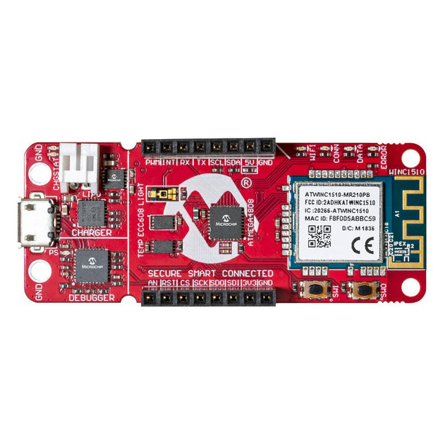
The AVR-IoT WA development board combines a powerful ATmega4808 AVR MCU, an ATECC608A CryptoAuthentication secure element IC and the fully certified ATWINC1510 Wi-Fi network controller – which provides the most simple and effective way to connect your embedded application to Amazon Web Services (AWS). The board also includes an on-board debugger, and requires no external hardware to program and debug the MCU.
Out of the box, the MCU comes preloaded with a firmware image that enables you to quickly connect and send data to the AWS platform using the on-board temperature and light sensors. Once you are ready to build your own custom design, you can easily generate code using the free software libraries in Atmel START or MPLAB Code Configurator (MCC).
The AVR-IoT WA board is supported by two award-winning Integrated Development Environments (IDEs) – Atmel Studio and Microchip MPLAB X IDE – giving you the freedom to innovate with your environment of choice.
Features
ATmega4808 microcontroller
Four user LED’s
Two mechanical buttons
mikroBUS header footprint
TEMT6000 Light sensor
MCP9808 Temperature sensor
ATECC608A CryptoAuthentication™ device
WINC1510 WiFi Module
On-board Debugger
Auto-ID for board identification in Atmel Studio and Microchip MPLAB X
One green board power and status LED
Programming and debugging
Virtual COM port (CDC)
Two DGI GPIO lines
USB and battery powered
Integrated Li-Ion/LiPo battery charger
The Giga Display Shield is a touch screen solution designed to effortlessly deploy graphic interfaces in your projects. Leveraging the new pin header connector in the middle of Giga R1 WiFi, this shield offers seamless integration and enhanced functionalities.
With the Giga Display Shield, you gain access to an array of features, including a digital microphone, 6-axis IMU, and Arducam connector. These added capabilities allow you to fully utilize the other 54 available pins, making it incredibly convenient to create handheld devices or dashboards to control your project.
Specifications
Display
KD040WVFID026-01-C025A
Size
3.97”
Resolution
480x800 RGB
Color
16.7M
Touch Mode
Five points and Gestures
Interface
I²C
Sensors
IMU
BMI270
Microphone
MP34DT06JTR
Downloads
Datasheet
Schematics
The Home Automation HAT uses only pluggable connectors. In addition, the latest release (V4.0 and up) has two new communication ports: 1-Wire and RS485. The card uses only 5 V power. On-board step-up power supply generates 12 V to power the 0-10 V analog outputs. A general purpose push-button, wired directly to a Raspberry Pi GPIO pin, can be used to shut down Raspberry Pi without a keyboard, or to force any output to a desired state. Ideal solution for your Raspberry Pi Home Automation projects. Read temperatures in up to 8 zones with analog inputs. Control your heating and cooling system with the 8 onboard relays. Use the 8 optically isolated digital inputs for your security system. Activate the hardware watchdog to monitor and power cycle the Raspberry Pi in case of software lockup. Control four-light systems with the four PWM open-drain outputs (you supply external power up to 24 V). Control four light dimmers using 0-10 V outputs. Compatibility The card is compatible with all Raspberry Pi versions from Zero to 4. It shares the I²C bus using only two of the Raspberry Pi’s GPIO pins to manage all eight cards. This feature leaves the remaining 24 GPIOs available for the user. Power Requirements The Home Automation card needs 5 V to operate and can be powered from Raspberry Pi or from its own pluggable connector. The onboard relay coils are also powered from the 5 V. An on-board 5V to 12V step-up power supply generates the voltage to drive the 0-10 V analog outputs. A local 3.3 V regulator powers the rest of the circuitry. The card needs 50 mA to operate with all relays off. Each relay needs up to 80 mA to turn on. Relays The 8 on-board relays have contacts brought out to heavy duty pluggable connectors, which make the card easy to use when multiple cards are stacked up. Relays are grouped in two sections of four relays each, with one common terminal and one N-O contact for each relay. Relays are rated 10 A/24 VDC and 250 VAC, but due to the board geometry limitation, the relays can switch only 3 A and 24 V, AC or DC. Status LEDs show when RELAYS are ON or OFF. Stacking Multiple Cards Up to eight Home Automation cards can be stacked on your Raspberry Pi. Each card is identified by jumpers you install to indicate the level in the stack. Cards can be installed in any order. The three position jumper on the upper right corner of the card selects the stack level. Features Eight relays with status LEDs and and N.O contacts Eight layer stackable Eight 12-bit A/D inputs, 250 Hz sample rate Four 13-bit DAC outputs (0-10 V dimmers) Four PWM 24 V/4 A open-drain outputs Eight optically isolated digital inputs Contact closure/Event counters up to 500 Hz Four Quadrature Encoder inputs 26 GPIOs from Raspberry Pi available 1-WIRE and RS485 communication ports Pluggable Connectors 26-16 AWG for all ports On-board hardware watchdog On-board resettable fuse Reverse power supply protection Brass stand-offs, screws and nuts included Hardware self-test with loop-back cable Open source hardware, schematics available 32-bit Processor running at 64 MHz Uses only I²C port (address 0x28..0x2f ), all GPIO pins available Specifications Power supply: Pluggable Connector, 5 V/3 A Power consumption: 50 mA (all relays off), 700 mA (all relays on) On board resettable fuse: 3 A Open Drain outputs: maximum 3 A, 24 V Relays 1,2,3,4,5,8: N-O contacts, 6 A/24 VAC or DC Relays 6,7: 3 A/24 VAC or DC Analog Inputs: Maximum input voltage: 3 V Input Impedance: 50 KΩ Resolution: 12 bits Sample rate: 250 samples/sec. DAC Outputs: Resistive load: Minimum 1 KΩ Accuracy: ±1% Opto-isolated Digital Inputs: Input Forward Current: Typical 5 mA, maximum 50 mA Input Series Resistor: 1K Input Reverse Voltage: 5 V Input Forward Voltage: 25 V @ 10 mA Isolation Resistance: Minimum 1012 Ω Included Home Automation stackable Card for Raspberry Pi with self-test Card Mounting hardware 4x M2.5x18 mm male-female brass standoffs 4x M2.5x5 mm brass screws 4x M2.5 brass nuts 2x Stack level Jumpers All required Connector Plugs Laminated Plastic Card showing IO Pinout Downloads User's Guide Open Source Hardware Schematic 2D CAD Drawing Command Line Python Libraries Node-RED Nodes Domoticz Plugin OpenPLC
This set includes all necessary tools to start soldering, plus two festive minikits to put your skills to the test.
The basic tools for soldering are a soldering iron (110 V AC version) and a support piece. We also included lead-free solder which is pretty easy to work with and its fumes are not harmful! Lastly, you’ll need some side cutters to trim the component’s leads.
The first minikit is the electronic candle, it has a warm yellow LED that mimics a real candle! This little solder kit only has 6 components to solder, which makes it the ideal starter kit.
Then it’s time to expand your skills with the original electronic Christmas tree kit. Solder more advanced components and a whopping 16 red LEDs.
Each kit is accompanied by an illustrated and comprehensive manual to make sure that anyone can master the art of soldering.
Features
Soldering iron and support (230 V AC version)
Lead-free solder
Side cutters
2 minikits
This QWIIC connector allows you to easily connect QWIIC enabled modules to a Raspberry Pi, without the need for soldering. It uses a 2x3 pin female header which sits on top of the first 6 GPIO pins and breaks out the 3.3v, GND and the two I²C pins (SDA, SCL) on a 4 pin JST connector which sits on top.
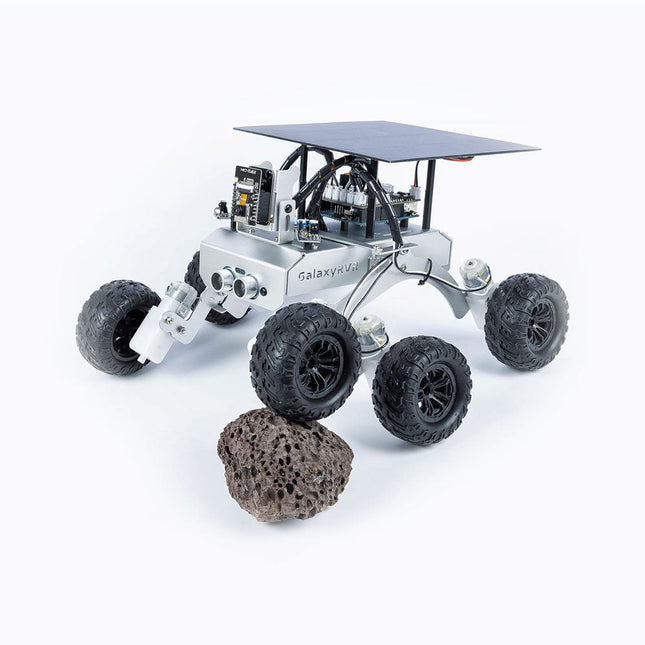
The SunFounder GalaxyRVR Mars Rover Kit was designed to mimic the functionality of real Mars rovers, it offers a hands-on experience that’s both educational and exciting. Compatible with Uno R3, the GalaxyRVR is equipped to navigate diverse terrains with ease. Whether you’re traversing sand, rocks, grass, or mud, this sturdy aluminum-alloy rover, modeled with a rocker-bogie suspension system, ensures smooth and seamless exploration.
What sets the GalaxyRVR apart is its innovative solar-powered design. With a built-in solar panel and rechargeable battery, the rover offers extended operation while embracing eco-friendly energy solutions. Coupled with an ESP32-CAM and an intuitive app, it delivers a real-time First-Person View (FPV) experience, immersing you in the rover’s journey as you control it remotely from virtually anywhere.
Smart navigation is at the heart of the GalaxyRVR. Its ultrasonic and infrared sensors enable precise obstacle detection and avoidance, ensuring uninterrupted exploration. To add to its versatility, vibrant RGB light strips and ESP32-controlled LED lighting make it possible to confidently navigate in low-light conditions, illuminating the rover’s path and adding a touch of brilliance to its adventures.
The kit includes detailed online tutorials (available in English, German, French, Spanish, Italian and Japanese), step-by-step video lessons, and access to a supportive community forum.
Features
Built with a durable aluminum alloy frame and a unique rocker-bogie system, this rover effortlessly tackles diverse terrains.
Solar-powered and equipped with an ESP32-CAM for real-time FPV visuals.
Intelligent sensors ensure smooth navigation around obstacles.
Specifications
Mainboard
SunFounder Uno R3
Wifi
ESP32-CAM
Programming language
C++
Control method
App controller
Input modules
Ultrasonic sensor, obstacle avoidance sensor
Output modules
WS2812 RGB board
Battery life
130 minutes
Charging methods
Solar charging, USB-C
Functions
Climb over, FPV, obstacle avoidance, illumination, voice control
Material
Aluminum alloy
Downloads
Online Tutorial
M5Stamp Fly is a programmable open-source quadcopter, featuring the StampS3 as the main controller. It integrates a BMI270 6-axis gyroscope and a BMM150 3-axis magnetometer for attitude and direction detection. The BMP280 barometric pressure sensor and two VL53L3 distance sensors enable precise altitude hold and obstacle avoidance. The PMW3901MB-TXQT optical flow sensor provides displacement detection.
The kit includes a buzzer, a reset button, and WS2812 RGB LEDs for interaction and status indication. It is equipped with a 300 mAh high-voltage battery and four high-speed coreless motors. The PCB features an INA3221AIRGVR for real-time current/voltage monitoring and has two Grove connectors for additional sensors and peripherals.
Preloaded with debugging firmware, the Stamp Fly can be controlled using an Atom Joystick via the ESP-NOW protocol. Users can choose between automatic and manual modes, allowing for easy implementation of functions like precise hovering and flips. The firmware source code is open-source, making the product suitable for education, research, and various drone development projects.
Applications
Education
Research
Drone development
DIY projects
Features
M5StampS3 as the main controller
BMP280 for barometric pressure detection
VL53L3 distance sensors for altitude hold and obstacle avoidance
6-axis attitude sensor
3-axis magnetometer for direction detection
Optical flow detection for hovering and displacement detection
Buzzer
300 mAh high-voltage battery
Current and voltage detection
Grove connector expansion
Specifications
M5StampS3
ESP32-S3@Xtensa LX7, 8 MB Flash, WiFi, OTG\CDC support
Motor
716-17600kv
Distance Sensor
VL53L3CXV0DH/1 (0x52) @ max 3 m
Optical Flow Sensor
PMW3901MB-TXQT
Barometric Sensor
BMP280 (0x76) @ 300-1100hPa
3-axis Magnetometer
BMM150 (0x10)
6-axis IMU Sensor
BMI270
Grove
I²C+UART
Battery
300mAh 1S high-voltage lithium battery
Current/Voltage Detection
INA3221AIRGVR (0x40)
Buzzer
Built-in Passive Buzzer @ 5020
Operating temperature
0-40°C
Dimensions
81.5 x 81.5 x 31 mm
Weight
36.8 g
Included
1x Stamp Fly
1x 300 mAh high-voltage Lithium battery
Downloads
Documentation
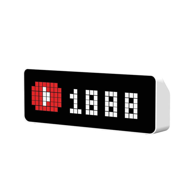
Ulanzi TC001 is an LED pixel clock consisting of 256 individual addressable RGB LEDs (8x32) with built-in battery, buzzer, light, temperature and humidity sensor. The integrated rechargeable battery offers a runtime of up to 5 hours. The WiFi connection to the clock is made via an ESP32 chip. Ulanzi TC001 uses an ESP32-WROOM-32D module.
Features
Pixelated message display
Simultaneous Display of the Number of Followers: Fan growth is immediately visible, suitable for YouTube, Bilibili, and Weibo.
Pomodoro Clock Design: Manage your own time more scientifically.
Explore unlimited possibilities: Multiple programs need to be installed through the control server to achieve more functions.
Awtrix Makes it Better: Awtrix simulator in TC001’s firmware simulates an Awtrix matrix and allows you to control the clock using a standard Awtrix host.
Hi-tech and stunning appearance: Modeling simple atmosphere, LED full-color pixel screen with better imaging.
Built-in 4400 mAh battery with up to 5 hours of battery life.
Specifications
Number of LEDs: 256 (8x32)
Operating voltage: 3.7 V
Power: 3 W
Battery capacity: 4400 mAh
Interface: USB-C
Dimensions: 200.6 x 70.3 x 31.9 mm
Weight: 283 g
Inbegrepen
Ulanzi TC001 Smart Pixel Clock
USB cable
Manual
Downloads
Firmware
This tool set contains essential tools for all kinds of electronic work.
Included
Soldering iron
Desoldering pump
Precision screwdriver 2.5x75 mm
Screwdriver 3x75 mm
Screwdriver 5x75 mm
Screwdriver 6x125 mm
Long nose plier (5')
Diagonal cutting plier (4.5')
IC extractor
Wire stripper & cutter
Multimeter
Hex key wrench
Soldering wire
Component storage box
Tweezers (Long nose)
Bag size: 340 x 210 x 50 mm
The Speaker Kit for Raspberry Pi is a small amplified speaker designed for the Raspberry Pi. Included MonkMakes Amplified Speaker Set of 10 female to female header wires Short stereo audio lead Raspberry Leaf GPIO template Downloads Instructions Datasheet
With a 6x20 grid of 2.54 mm spaced holes for easy soldering and labelled Pico pins so you know what's what, Pico Proto is perfect for when you're happy with your breadboard project and want to give it a secure, smart and compact long-term home. Pico Proto doesn't come with any headers attached, so you will need to either solder it directly to your Pico's male header pins (for a permanent, but super slim sandwich) or solder it to some female header. Features 40 2.54 mm spaced holes for attaching to your Pico. 120 2.54 mm spaced holes (6x20 grid) for attaching other things Compatible with Raspberry Pi Pico. Dimensions: approx 51 x 25 x 1 mm (L x W x H)
The HuskyLens AI Camera intuitive design allows the user to control different aspects of the camera just by pressing buttons. You can start and stop learning new objects and even switch between algorithms from the device.
To further reduce the need to be connected to a PC the HuskyLens AI Camera comes with a 2-inch display so you can see what's going on in real time.
Specifications
Processor: Kendryte K210
Image Sensor: OV2640 (2.0 Megapixel Camera)
Supply Voltage: 3.3~5.0 V
Current Consumption (TYP): 320 mA @ 3.3 V, 230 mA @ 5.0 V (face recognition mode; 80% backlight brightness; fill light off)
Connection Interface: UART, I²C
Display: 2.0-inch IPS screen with 320x240 resolution
Built-in Algorithms: Face Recognition, Object Tracking, Object Recognition, Line Tracking, Color Recognition, Tag Recognition
Dimension: 52 x 44.5 mm (2.05 x 1.75')
Included
1x HuskyLens Mainboard
6x M3 Screws
6x M3 Nuts
1x Small Mounting Bracket
1x Heightening Bracket
1x Gravity 4-Pin Sensor Cable
The SparkFun RedBoard Qwiic is an Arduino-compatible board that combines features of different Arduinos with the Qwiic Connect System.
Features
ATmega328 microcontroller with Optiboot Bootloader
R3 Shield Compatible
CH340C Serial-USB Converter
3.3 V to 5 V Voltage Level Jumper
A4 / A5 Jumpers
AP2112 Voltage Regulator
ISP Header
Input voltage: 7 V - 15 V
1 Qwiic Connector
16 MHz Clock Speed
32 k Flash Memory
All SMD Construction
Improved Reset Button
Features No backlight Displays last images even when powered down Ultra low power consumption SPI interface Compatible with 3.3 V and 5 V Specifications Operating voltage 3.3 V / 5 V Interface 3-wire SPI, 4-wire SPI Outline dimension 89.5 x 38 mm Display size 66.89 x 29.05 mm Dot pitch 0.138 x 0.138 Resolution 296 x 128 Display color red, black, white Grey level 2 Full refresh time 15 s Refresh power 26.4 mW Standby power <0.017 mW Viewing angle >170° For more information check out the waveshare wiki here.