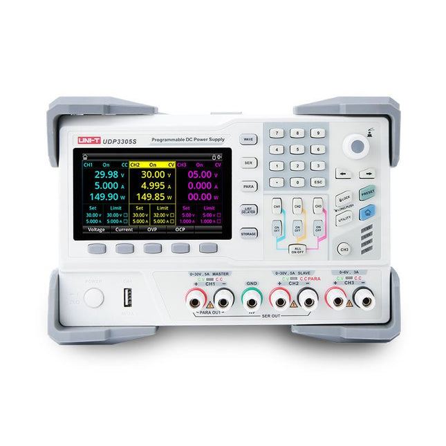
The UDP3305S-E is a high-performance programmable linear DC power supply. It has a clear LCD user interface, excellent performance indicators, a variety of analysis functions and communication interfaces. It can meet the diversified test needs of users. It aims to provide cost-effective DC programmable power supply equipment for teaching, scientific research, industry and other fields.
LCD interactive interface
Using a 4.3-inch high-definition display screen, it provides users with a man-machine interface with rich functions and simple operation, which can display the current set output voltage/current, actual output voltage/current and protection output voltage/current value of the power supply in real time. The functional interface is simple and comprehensive, easy to operate.
One-key setting for series and parallel
The series-parallel connection between CH1 and CH2 of the main channel can be realized without external connection, which simplifies the connection and makes the test easier.
List/Delayer function
With list and delay setting functions, it can set up to 2048 sets of data according to test requirements, and the number of cycles can reach 99999. It is used with waveform templates, which is very convenient for cycle testing and aging testing.
Rich remote control interface
Standard RS232 communication interface, Ethernet interface, Digital I/O and master and slave USB interfaces, can be controlled by remote connection to Ethernet, or through RS232 and USB, with the host computer software to achieve software control.
Specifications
Type
Linear DC power supply
Channels
4
Total power
328 W
Output voltage
CH1/CH2: 0~30 VCH3: 0~6 VCH4: 5 V
Output current
CH1/CH2: 0~5 ACH3: 0~3 ACH4: 2 A
Resolution
10 mV, 1 mA
Setting accuracy
0.3% +20 mV<0.2% +5 mA
Connectivity
USB Device, RS-232, LAN, USB host, Digital I/O
Included
1x UDP3305S-E DC Power Supply
1x Power cord
1x USB cable
Downloads
Datasheet
User manual
Programming manual
Software V1.0
Firmware V1.10
This PCIe to M.2 adapter is specifically designed for the Raspberry Pi 5. It supports the NVMe protocol for M.2 SSDs, enabling fast read and write operations, and adheres to the HAT+ standard. The adapter is compatible with M.2 SSDs in the 2230 and 2242 sizes.
Included
1x PCIe to M.2 HAT+ Adapter
1x 2x20 Pin header
1x 16P cable (40 mm)
1x Standoff pack
Downloads
Wiki
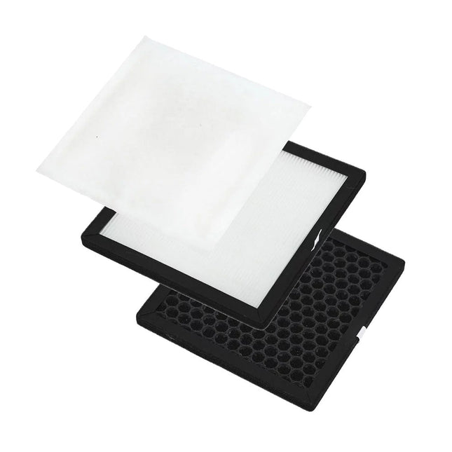
This complete replacement filter set for the Aoyue 8486 Fume Extractor contains a HEPA (High Efficiency Particulate Air) filter, a cotton air (sub) filter and an activated carbon air filter.
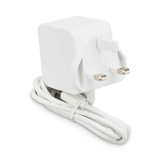
The Raspberry Pi 27 W PD USB-C power supply is designed specifically to power the Raspberry Pi 5. It is also capable of delivering 5 V/3 A, 9 V/3 A, 12 V/2.25 A, 15 V/1.8 A to PD-compatible products, making it a good and cost-effective power supply for many general applications, such as charging smartphones and tablets.
Specifications
Input
100-240 V AC
Output
5 A @ 5.1 V, 3 A @ 9 V, 2.25 A @ 12 V, 1.8 A @ 15 V
Connector
USB-C
Length
1.2 m
Color
White
Region
UK
NetPi is the perfect solution for your Raspberry Pi Pico's connectivity needs. It's an Ethernet HAT that enables your Pico to easily connect to the internet. With support for various internet protocols such as TCP, UDP, WOL over UDP, ICMP, IPv4, and more, NetPi can create IoT devices, robots, home automation systems, and industrial control systems.
It has four independent SOCKETs that can be used simultaneously, and it also supports SOCKET-less commands like ARP-Request and PING-Request. The Ethernet HAT is equipped with 10Base-T/100Base-TX Ethernet PHY and auto-negotiation for a full and half duplex with 10 and 100-based connections. NetPi is ideal for various applications.
With NetPi, you can now support hardwired internet protocols like TCP, UDP, ICMP, and more. Enjoy four independent sockets for simultaneous connections and perform socket-less commands like ARP-Request and PING-Request. NetPi also supports Ethernet power down mode and wake on LAN over UDP for energy-saving.
NetPi is equipped with a 10Base-T/100Base-TX Ethernet PHY and supports auto-negotiation for a full and half duplex with 10 and 100-based connections. The device features network indicator LEDs for full/half duplex, link, 10/100 speed, and active status.
Features
Compatible with Raspberry Pi Pico (W)
Built-in RJ45 with Transformer: Ethernet Port
Support 4 independent SOCKETs simultaneously
Support Hardwired TCP/IP Protocols: TCP, UDP, ICMP, IPv4, ARP, IGMP, PPPoE
Ethernet power down mode and Wake on LAN over UDP for energy-saving
10Base-T/100Base-TX Ethernet PHY with auto-negotiation for full and half duplex with 10 and 100-based connections
Network indicator LEDs for full/half duplex, link, 10/100 speed, and active status
RP2040 pins breakout with female pin header for other shield and peripheral interfacing
1.3' TFT LCD (240 x 240) and a 5-way joystick for user experience
SPI, I²C, UART interfacing
Dimensions: 74.54 x 21.00 mm
Applications
Internet of Things (IoT) devices
Industrial automation and control systems
Home automation and smart home systems
Remote monitoring and data logging systems
Robotics and autonomous systems
Networked sensor systems
Building automation and energy management systems
Security and access control systems
Downloads
GitHub
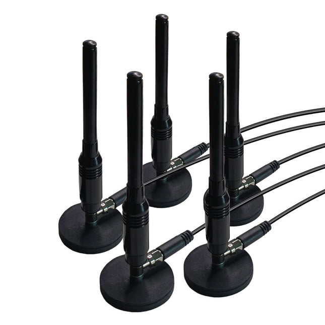
This is a set of five magnetic, telescopic whip antennas – with 100 MHz to 1 GHz tuning range – that can be used with KrakenSDR for direction finding. The magnets are strong and will be secure on the roof of a moving car. It includes a set of five two-meter, LMR100-equivalent coax cables that have been length matched for better performance.
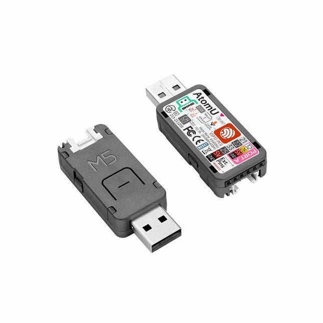
ATOM U is a compact low-power consumption speech recognition IoT development kit. It adopts an ESP32 chipset, equipped with 2 low-power Xtensa 32-bit LX6 microprocessors with the main frequency of up to 240 MHz. Built-in USB-A interface, IR emitter, programmable RGB LED. Plug-and-play, easy to upload and download programs. Integrated Wi-Fi and digital microphone SPM1423 (I2S) for the clear sound record. suitable for HMI, Speech-to-Text (STT). Low-code development ATOM U supports UIFlow graphical programming platform, scripting-free, cloud push; Fully compatible with Arduino, MicroPython, ESP32-IDF, and other mainstream development platforms, to quickly build various applications. High integration ATOM U contains a USB-A port for programming/power supply, IR emitter, programmable RGB LED x1, button x1; Finely tuned RF circuit, providing stable and reliable wireless communication. Strong expandability ATOM U is easy access to M5Stack's hardware and software system. Features ESP32-PICO-D4 (2.4GHz Wi-Fi dual mode) Integrated programmable RGB LED and button Compact design Built-in IR emitter Expandable pinout and GROVE port Development platform: UIFlow MicroPython Arduino Specifications ESP32-PICO-D4 240MHz dual core, 600 DMIPS, 520KB SRAM, 2.4G Wi-Fi Microphone SPM1423 Microphone sensitivity 94 dB SPL@1 KHz Typical value: -22 dBFS Microphone signal-to-noise ratio 94 dB SPL@1 KHz, A-weighted Typical value: 61.4 dB Standby working current 40.4 mA Support input sound frequency 100 Hz ~ 10 KHz Support PDM clock frequency 1.0 ~ 3.25 MHz Weight 8.4 g Product size 52 x 20 x 10 mm Downloads Documentation
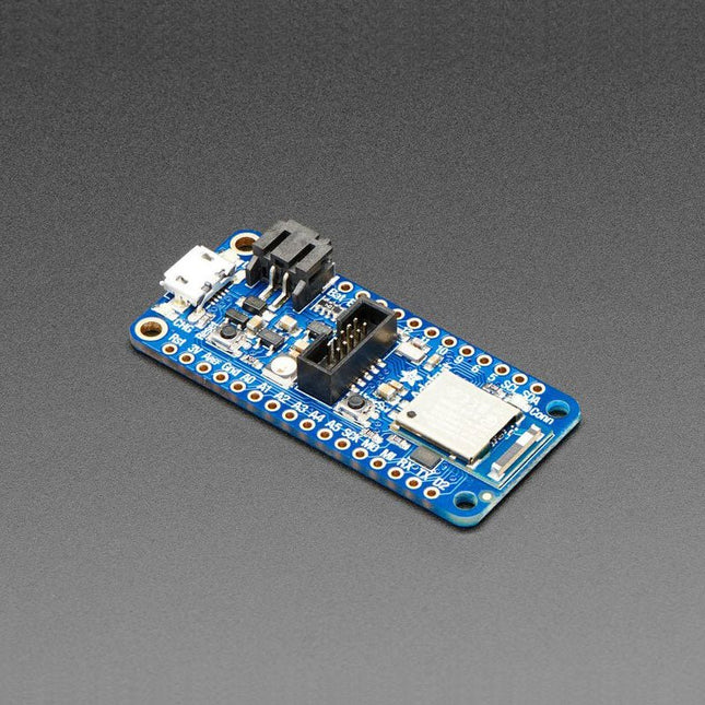
You can program the nRF52840 chip directly to take full advantage of the Cortex-M4 processor, and then calling into the Nordic SoftDevice radio stack when you need to communicate over BLE. Since the underlying API and peripherals are the same for the '832 and '840, you can supercharge your older nRF52832 projects with the same exact code, with a single recompile! CircuitPython works best with disk drive access, and this is the only BLE-plus-USB-native chip that has the memory to handle running a little Python interpreter. The massive RAM and speedy Cortex M4F chip make this a good match. Peripherals Plenty of GPIO, analog inputs, PWM, timers, etc. Best of all, it's got that native USB! Finally, no need for a separate USB serial chip like CP2104 or FT232. Serial is handled as a USB CDC descriptor, and the chip can act like a keyboard, mouse, MIDI device, or even disk drive. This chip has TinyUSB support – that means you can use it with Arduino as a native USB device and act as UART (CDC), HID, Mass Storage, MIDI, and more! Features ARM Cortex M4F (with HW floating point acceleration) running at 64 MHz 1 MB flash and 256 KB SRAM Native Open Source USB stack (pre-programmed with UF2 bootloader) Bluetooth Low Energy compatible 2.4 GHz radio FCC / IC / TELEC certified module Up to +8 dBm output power 1.7 V to 3.3 V operation with internal linear and DC/DC voltage regulators 21 GPIO, 6x 12-bit ADC pins, up to 12 PWM outputs (3 PWM modules with 4 outputs each) Pin #3 red LED for general purpose blinking, NeoPixel for colorful feedback Power/enable pin Measures 2.0 x 0.9 x 0.28' (51 x 23 x 7.2 mm) without headers soldered in Light as a (large?) feather (6 grams) 4 mounting holes Reset button SWD connector for debugging
Specifications
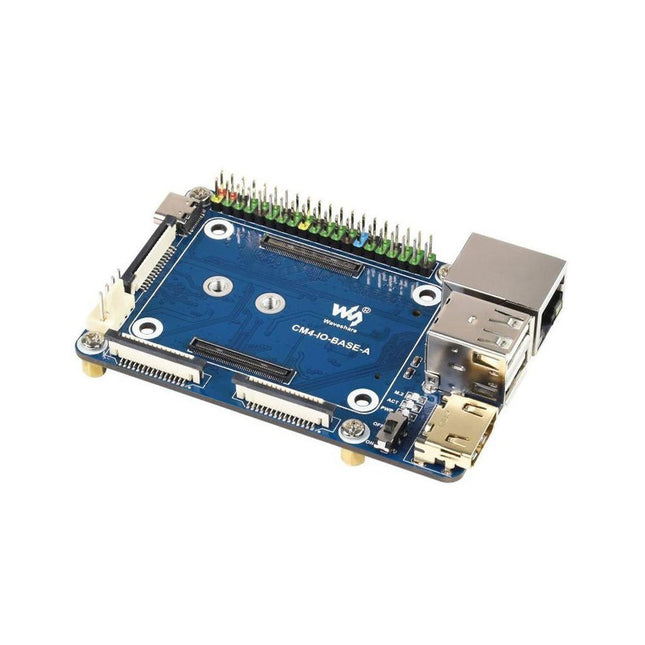
CM4 socket
Suitable for all variants of Compute Module 4
Networking
Gigabit Ethernet RJ45 connectorM.2 M KEY, supports communication modules or NVME SSD
Connector
Raspberry Pi 40-PIN GPIO header
USB
2x USB 2.0 Type A2x USB 2.0 via FFC connector
Display
MIPI DSI display port (15-pin 1.0 mm FPC connector)
Camera
2x MIPI CSI-2 camera port (15-pin 1.0 mm FPC connector)
Video
2x HDMI port (including one port via FFC connector), supports 4K 30fps output
RTC
N/A
Storage
MicroSD card socket for Compute Module 4 Lite (without eMMC) variants
Fan header
No fan control, 5 V
Power input
5 V
Dimensions
85 x 56 mm
Included
1x CM4-IO-BASE-A
1x SSD mounting screw
Downloads
Wiki
A modern USB-C connector makes programming easy. In addition to the pins broken out, two separate Qwiic-enabled I²C ports allow you to easily daisy chain Qwiic-enabled devices. We've exposed the SWD pins for more advanced users who prefer to use professional tools' power and speed. A USB-A connector is provided for Processor Boards that have USB Host support. A backup battery is provided for processor boards with RTC. If you need a 'lot' of GPIO with a simple-to-program, ready for the market module, the ATP is the fix you need. We've even added a convenient jumper to measure the current consumption for low power testing. Features M.2 Connector Operating Voltage Range ~3.3 V to 6.0 V (via VIN to AP7361C 3.3V Voltage Regulator) 3.3 V (via 3V3) Ports 1x USB type C 1x USB type A Host 2x Qwiic Enabled I²C 1x CAN 1x I²S 2x SPI 2x UARTs 2x Dedicated Analog Pins 2x Dedicated PWM Pins 2x Dedicated Digital Pins 12x General Purpose Input Output Pins 1x SWD 2x5 header 1 mAh battery backup for RTC Buttons Reset Boot LEDs Power 3.3 V Phillips #0 M2.5x3mm screw included
The Maker pHAT is the solution to the most common problems beginners face starting with Raspberry PI. Its intelligent and simple design makes it easy to attach to your Pi, and it helps you avoid all the tedious work of connection various other accessories. Additionally, the LEDs corresponding to each pin makes it extremely easy to see where a potential problem lies The Maker pHat has the same size as the Raspberry Pi Zero with all 4mounting holes aligned. However, it can be used with Raspberry Pi 3B, 3B+ and 3A+, by inserting a 2 x 20 stacking header. Features Raspberry Pi Zero size, stack perfectly on to Raspberry Pi Zero Compatible with standard size Raspberry Pi 3B / 3B+, medium size Raspberry Pi 3A+ and smaller size Raspberry Pi Zero / W / WH. Standard Raspberry Pi GPIO footprint. LED array for selected GPIO pins (GPIO 17, 18, 27, 22, 25, 12, 13, 19). 3x on board programmable push buttons (GPIO 21, 19 and 20, need to configure as input pull up). Onboard active buzzer (GPIO 26). Proper labels for all GPIOs, including SPI, UART, I2C, 5V, 3.3V, and GND. Utilize USB Micro-B socket for 5V input and USB to UART communication. USB serial facilitated by the FT231X
Input voltage: USB 5 V, from a computer, power bank or a standard USB adapter. Mount on Raspberry Pi Zero Mount on Raspberry Pi 3B, 3B+ and 3A+
The Raspberry Pi AI HAT+ is an expansion board designed for the Raspberry Pi 5, featuring an integrated Hailo AI accelerator. This add-on offers a cost-effective, efficient, and accessible approach to incorporating high-performance AI capabilities, with applications spanning process control, security, home automation, and robotics.
Available in models offering 13 or 26 tera-operations per second (TOPS), the AI HAT+ is based on the Hailo-8L and Hailo-8 neural network accelerators. This 13 TOPS model efficiently supports neural networks for tasks like object detection, semantic and instance segmentation, pose estimation, and more. The 26 TOPS variant accommodates larger networks, enables faster processing, and is optimized for running multiple networks simultaneously.
The AI HAT+ connects via the Raspberry Pi 5’s PCIe Gen3 interface. When the Raspberry Pi 5 is running a current version of the Raspberry Pi OS, it automatically detects the onboard Hailo accelerator, making the neural processing unit (NPU) available for AI tasks. Additionally, the rpicam-apps camera applications included in Raspberry Pi OS seamlessly support the AI module, automatically using the NPU for compatible post-processing functions.
Included
Raspberry Pi AI HAT+ (13 TOPS)
Mounting hardware kit (spacers, screws)
16 mm GPIO stacking header
Downloads
Datasheet
YDLIDAR SDM18 is a high-performance single-point LiDAR. Based on the principle of ToF, it is equipped with related optics, electricity, and algorithm design to achieve high-precision laser distance measurement and outputting high frame rate point cloud data of the scanning environment. It can be used for UAV alt-hold, robot obstacle avoidance and navigation, etc.
Specifications
High Ranging frequency: 50-250 Hz
Range Distance: 0.2-18 m
FDA Class I eye safety standard
Support UART and I²C interfaces
Dimensions: 21 x 15 x 7.87 mm
Weight: 1.35 g
Applications
UAV alt-hold and obstacle avoidance
Robot obstacle avoidance
Intelligent equipment obstacle avoidance
Navigation and obstacle avoidance of home service robots / robot vacuum cleaners
Downloads
Datasheet
User Manual
Development Manual
SDK
Tool
ROS
The Arduino Nano 33 BLE Rev2 stands at the forefront of innovation, leveraging the advanced capabilities of the nRF52840 microcontroller. This 32-bit Arm Cortex-M4 CPU, operating at an impressive 64 MHz, empowers developers for a wide range of projects. The added compatibility with MicroPython enhances the board's flexibility, making it accessible to a broader community of developers.
The standout feature of this development board is its Bluetooth Low Energy (Bluetooth LE) capability, enabling effortless communication with other Bluetooth LE-enabled devices. This opens up a realm of possibilities for creators, allowing them to seamlessly share data and integrate their projects with a wide array of connected technologies.
Designed with versatility in mind, the Nano 33 BLE Rev2 is equipped with a built-in 9-axis Inertial Measurement Unit (IMU). This IMU is a game-changer, offering precise measurements of position, direction, and acceleration. Whether you're developing wearables or devices that demand real-time motion tracking, the onboard IMU ensures unparalleled accuracy and reliability.
In essence, the Nano 33 BLE Rev2 strikes the perfect balance between size and features, making it the ultimate choice for crafting wearable devices seamlessly connected to your smartphone. Whether you're a seasoned developer or a hobbyist embarking on a new adventure in connected technology, this development board opens up a world of possibilities for innovation and creativity. Elevate your projects with the power and flexibility of the Nano 33 BLE Rev2.
Specifications
Microcontroller
nRF52840
USB connector
Micro USB
Pins
Built-in LED Pins
13
Digital I/O Pins
14
Analog Input Pins
8
PWM Pins
All digital pins (4 at once)
External interrupts
All digital pins
Connectivity
Bluetooth
u-blox NINA-B306
Sensors
IMU
BMI270 (3-axis accelerometer + 3-axis gyroscope) + BMM150 (3-axis Magnetometer)
Communication
UART
RX/TX
I²C
A4 (SDA), A5 (SCL)
SPI
D11 (COPI), D12 (CIPO), D13 (SCK). Use any GPIO for Chip Select (CS)
Power
I/O Voltage
3.3 V
Input Voltage (nominal)
5-18 V
DC Current per I/O Pin
10 mA
Clock Speed
Processor
nRF52840 64 MHz
Memory
nRF52840
256 KB SRAM, 1 MB flash
Dimensions
18 x 45 mm
Downloads
Datasheet
Schematics
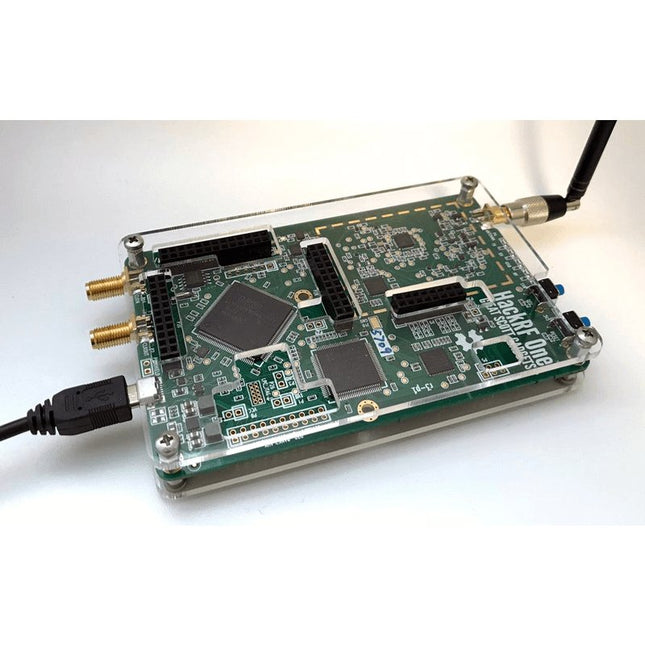
This clear acrylic case is the official case for the HackRF One board. It can replace the standard black plastic case of the HackRF One.
Assembly Instructions
Use a guitar pick or spudger to extract the HackRF One circuit board from the black plastic case.
Insert one long screw into each corner of the bottom acrylic panel. Secure each long screw with a short (5 mm) spacer on the opposite side of the panel.
Place the HackRF One circuit board (facing up) on top of the bottom panel, fitting the ends of the long screws through the corner mounting holes of the circuit board.
Secure the circuit board with one long (6 mm) spacer in each corner.
Place the top acrylic panel on top of the circuit board, aligning the cutouts with the circuit board’s expansion headers.
Secure each corner with a short screw.
Note: Do not overtighten! Hand-tighten only at every step.
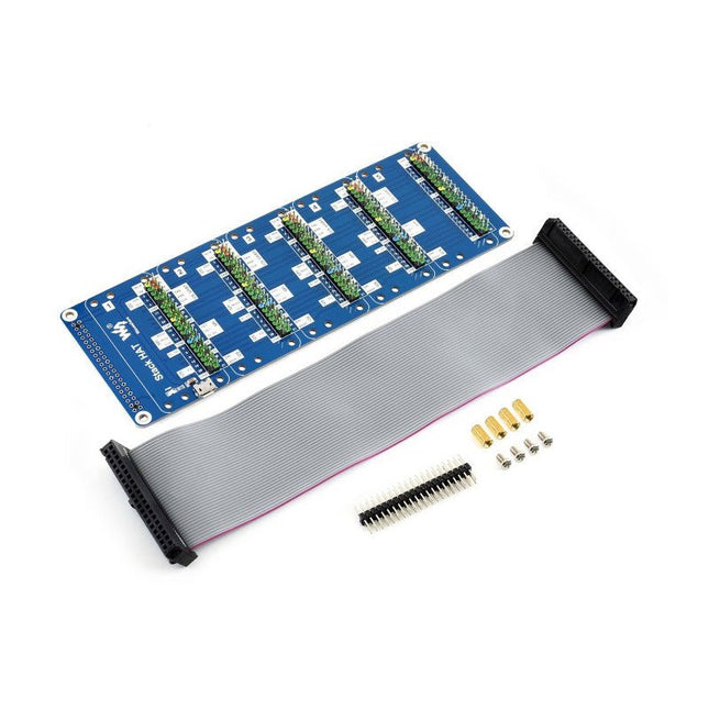
This is an I/O expansion kit designed for Raspberry Pi, which provides 5 sets of 2x20 pinheaders, that means a handy way to 'stack' multi different HATs together, and use them as a specific combination / project.
Features
Standard Raspberry Pi connectivity, directly pluggable OR through ribbon cable
5 sets of 2x20 pinheaders, connect multi HATs together
USB external power port, provides enough power supply for multi HATs
Clear and descriptive pin labels for easy use
Reserved jumper pads on the bottom side, pin connections are changeable by soldering, to avoid pin conflicts
Note: make sure there are no any pin conflicts between the HATs you want to use together before connecting.
Specifications
Dimensions: 183 × 65 mm
Mounting hole size: 3 mm
Included
1x Stack HAT
1x Ribbon cable 40-Pin
1x 2x20 male pinheader
1x RPi screws pack (4pcs) x1
With a Cortex-M4F with BLE 5.0 running up to 96MHz and with as low power as 6uA per MHz (less than 5mW), the M.2 MicroMod connector allows you to plug in a MicroMod Carrier Board with any number of peripherals. Let's have a look at what this processor board has to offer! If you need Machine Learning capabilities, Bluetooth, I²C functionality to connect to all our amazing Qwiic boards, and more the Artemis Processor is the perfect choice for your MicroMod Carrier Board. At the heart of SparkFun's Artemis Module is Ambiq Micro's Apollo3 processor, whose ultra-efficient ARM Cortex-M4F processor is spec’d to run TensorFlow Lite using only 6uA/MHz. We've routed two I²C buses, eight GPIO, dedicated digital, analogue, and PWM pins, multiple SPI as well as QuadSPI, and Bluetooth to boot. You really can't go wrong with this processor. Grab one today, pick up a compatible carrier board, and get hacking! Features 1 M Flash / 384 k RAM 48 MHz / 96 MHz turbo available 6uA/MHz (operates less than 5mW at full operation) 48 GPIO - all interrupt capable 31 PWM channels Built-in BLE radio and antenna 10 ADC channels with 14-bit precision with up to 2.67 million samples per second effective continuous, multi-slot sampling rate 2 channel differential ADC 2 UARTs 6 I²C buses 6 SPI buses 2/4/8-bit SPI bus PDM interface I²S Interface Secure 'Smart Card' interface FCC/IC/CE Certified (ID Number 2ASW8-ART3MIS)
1x USB dedicated for programming and debugging 1x UART with flow control 2 x I²C 1 x SPI 1 x Quad-SPI 8 x Fast GPIO 2 x Digital Pins 2 x Analog Pins 2 x PWM 1 x Differential ADC pair Status LED VIN Level ADC
The AxiDraw MiniKit 2 The AxiDraw MiniKit 2 is a special compact addition to the AxiDraw lineup. Designed for lighter-duty applications, It takes up less desk space and less storage space. It's considerably more portable, too. The AxiDraw MiniKit is also the only DIY kit model of AxiDraw that you get to assemble yourself. All other AxiDraw models ship fully assembled, tested, and ready to use.) A Mini Plotter The AxiDraw MiniKit 2 has a working area of about 6 × 4 inches (150 × 100 mm): Big enough to be useful for a wide range of applications including short notes, postcards, and addressing envelopes. It's also ideally suited for use as a signature machine, for signing checks, letters, books, or artwork. Applications The AxiDraw is an extremely versatile machine, designed to serve a wide variety of everyday and specialized drawing and writing needs. You can use it for almost any task that might normally be carried out with a handheld pen. It allows you to use your computer to produce writing that appears to be handmade, complete with the unmistakable appearance of using a real pen (as opposed to an inkjet or laser printer) to address an envelope or sign one's name. And it does so with precision approaching that of a skilled artist, and – just as importantly – using an arm that never gets tired. Specifications Performance Usable pen travel (inches): 6.3 × 4 inches Usable pen travel (millimeters): 160 × 101 mm Vertical pen travel: 0.7 inch (17 mm) Maximum XY travel speed: 10 inches (25 cm) per second Native XY resolution: 2032 steps per inch (80 steps per mm) Reproducibility (XY): Typically better than 0.005 inches (0.1 mm) at low speeds Physical Major structural components are machined, extruded, or folded aluminum, manufactured and anodized in the USA. Holds pens and other drawing instruments up to 5/8' (16 mm) diameter and 25 g weight. Overall dimensions: Approximately 14.25 × 9.25 × 4.25 inches (36 × 23.5 × 11 cm) Maximum height with cable guides: Approximately 9 inches (23 cm) Footprint: Approximately 13.5 × 1.7 inches (35 x 4.5 cm) Weight: 3.2 Lb (1.5 kg) Software Compatible with Mac, Windows, and Linux Drive directly from within Inkscape, using the AxiDraw extension Comprehensive user guide available for download
Driver software software free to download and open source Internet access is required to download software Additionally, AxiDraw Merge software available at no cost to AxiDraw owners. Programming interfaces Note: Programming is not required to use the AxiDraw Stand-alone command line interface (CLI) Available AxiDraw Python API
RESTful API available for full machine control, stand-alone or accessible by running RoboPaint in the background. Simplified 'GET-only' API available as well, for use in programming environments (such as Scratch, Snap) that permit only retrieval of URLs. Direct EiBotBoard (EBB) command protocol available for use in any programming environment that supports communication with USB-based serial ports. Code that generates SVG files can also be used to (indirectly) control the machine. Included All parts and materials necessary to build the AxiDraw MiniKit 2 writing and drawing machine. Multi-plug power supply with EU adapter USB cable Small Easel (Board and clips) for paper holding Tools needed Scissors or diagonal cutters Small Phillips-head screwdrivers: #0 and #1 sizes Small flat-head screwdriver: 2 mm or 5/64' blade width recommended Miniature pliers (Recommended but not required) Small hobby knife (Recommended but not required) Downloads User Guide
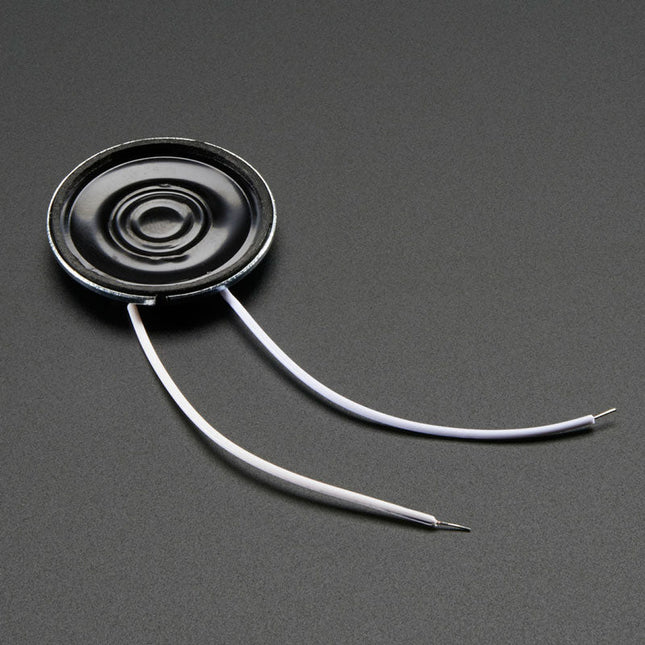
Specifications Datasheet Resonance Frequency (FO): 680 ±20% Hz at 1 V Rated Impedance: 8 ±20% Ω (at 1 KHz) Frequency Range: ~600-10 KHz Rated Input Power: 0.25 W Max Input Power: 0.5 W Temperature Range: -20ºC ~ 55ºC Dimensions Diameter: 28 mm / 1.1' Height: 4.5 mm Weight: 6 g
Learn KiCad with Peter Dalmaris
The Academy Pro Box "Design PCBs like a Pro" offers a complete, structured training programme in PCB design, combining online learning with practical application. Based on Peter Dalmaris’ KiCad course, the 15-week programme integrates video lessons, printed materials (2 books), and hands-on projects to ensure participants not only understand the theory but also develop the skills to apply it in practice.
Unlike standard courses, the Academy Pro Box provides a guided learning path with weekly milestones and physical components to design, test, and produce working PCBs. This approach supports a deeper learning experience and better knowledge retention.
The box is ideal for engineers, students, and professionals who want to develop practical PCB design expertise using open-source tools. With the added option to have their final project manufactured, participants complete the programme with real results – ready for use, testing, or further development.
Learn by doing
Build skills. Design real boards. Generate Gerbers. Place your first order. This isn’t just a course – it’s a complete project journey from idea to product.
You’ll walk away with:
Working knowledge of KiCad’s tools
Confidence designing your own PCBs
A fully manufacturable circuit board – made by you
What's inside the Box (Course)?
Both volumes of "KiCad Like a Pro" (valued at €105)
Vol 1: Fundamentals and Projects
Vol 2: Advanced Projects and Recipes
Coupon code to join the bestselling KiCad 9 online course by Peter Dalmaris on Udemy, featuring 20+ hours of video training. You'll complete three full design projects:
Breadboard Power Supply
Tiny Solar Power Supply
Datalogger with EEPROM and Clock
Voucher from Eurocircuits for the production of PCBs (worth €85 excl. VAT)
Learning Material (of this Box/Course)
15-Week Learning Program
▶ Click here to open
Week 1: Setup, Fundamentals, and First Steps in PCB Design
Week 2: Starting Your First PCB Project – Schematic Capture
Week 3: PCB Layout – From Netlist to Board Design
Week 4: Design Principles, Libraries, and Workflow
Week 5: Your First Real-World PCB Project
Week 6: Custom Libraries – Symbols, Footprints, and Workflow
Week 7: Advanced Tools – Net Classes, Rules, Zones, Routing
Week 8: Manufacturing Files, BOMs, and PCB Ordering
Week 9: Advanced Finishing Techniques – Graphics, Refinement, and Production Quality
Week 10: Tiny Solar Power Supply – From Schematic to Layout
Week 11: Tiny Solar Power Supply – PCB Layout and Production Prep
Week 12: ESP32 Clone Project – Schematic Design and Layout Prep
Week 13: ESP32 Clone – PCB Layout and Manufacturing Prep
Week 14: Final Improvements and Advanced Features
Week 15: Productivity Tools, Simulation, and Automation
KiCad Course with 18 Lessons on Udemy (by Peter Dalmaris)
▶ Click here to open
Introduction
Getting started with PCB design
Getting started with KiCad
Project: A hands-on tour of KiCad (Schematic Design)
Project: A hands-on tour of KiCad (Layout)
Design principles and PCB terms
Design workflow and considerations
Fundamental KiCad how-to: Symbols and Eeschema
Fundamental KiCad how-to: Footprints and Pcbnew
Project: Design a simple breadboard power supply PCB
Project: Tiny Solar Power Supply
Project: MCU datalogger with build-in 512K EEPROM and clock
Recipes
KiCad 9 new features and improvements
Legacy (from previous versions of KiCad)
KiCad 7 update (Legacy)
(Legacy) Gettings started with KiCad
Bonus lecture
About the Author
Dr. Peter Dalmaris, PhD is an educator, an electrical engineer and Maker. Creator of online video courses on DIY electronics and author of several technical books. As a Chief Tech Explorer since 2013 at Tech Explorations, the company he founded in Sydney, Australia, Peter's mission is to explore technology and help educate the world.
What is Elektor Academy Pro?
Elektor Academy Pro delivers specialized learning solutions designed for professionals, engineering teams, and technical experts in the electronics and embedded systems industry. It enables individuals and organizations to expand their practical knowledge, enhance their skills, and stay ahead of the curve through high-quality resources and hands-on training tools.
From real-world projects and expert-led courses to in-depth technical insights, Elektor empowers engineers to tackle today’s electronics and embedded systems challenges. Our educational offerings include Academy Books, Pro Boxes, Webinars, Conferences, and industry-focused B2B magazines – all created with professional development in mind.
Whether you're an engineer, R&D specialist, or technical decision-maker, Elektor Academy Pro bridges the gap between theory and practice, helping you master emerging technologies and drive innovation within your organization.
The Analog Thing V1.2 (in short THAT) is a high-quality, low-cost, open-source, and not-for-profit cutting-edge analog computer designed for desktop use to solve (sets of) differential equations. With its patch panel instead of keyboard, mouse, and monitor, its user interface differs noticeably from those of its digital stored-program cousins. The patch panel is divided into groups of analog computing elements such as integrators, summers, and multipliers.
THAT allows modeling dynamic systems with great speed, parallelism, and energy efficiency. Its use is intuitively interactive, experimental, and visual. It bridges the gap between hands-on practice and mathematical theory, integrating naturally with design and engineering practices such as speculative trial-and-error exploration and the use of scale models.
Dynamic system modeling on THAT can serve a variety of valuable purposes. It may help understand what is (models of), or it may help bring about what should be (models for). It may be used to explain in educational settings, to imitate in gaming, to predict in the natural sciences, to control in engineering, or it may be pursued for the pure joy of it!
THAT can be used with various kinds of oscilloscopes, such as conventional cathode ray tube oscilloscopes, digital oscilloscopes, and USB oscilloscopes in conjunction with PCs.
Features
5 Integrators – Circuits that perform integration over time.
4 Summers – Circuits that add inputs continously.
2 Comparators – Circuits that compare inputs to support conditional functions.
Master/Minion Ports – Interfaces that allow daisy-chaining multiple THATs to create arbitrarily large programs.
8 Coefficient Potentiometers – Rotary knobs to provide user-defined inputs.
2 Multipliers – Circuits that multiply inputs continously.
Panel Meter – A digital panel meter for precision measurements of values and timing.
Hybrid Port – An interface for controlling THAT digitally to develop analog-digital hybrid programs.
Included
1x RCA-RCA cable
30x Patch cables
6x Adhesive feet
1x Master to minion ribbon cable
1x USB-A to USB-C cable
1x Quick-start manual
Required
USB power supply
BNC adapters/cables to connect an oscilloscope
Downloads
First Steps
Documentation
This 10.1-inch HDMI touch screen has a high-definition resolution of 1280x800 and supports a viewing angle of 178°, providing an excellent visual experience. It supports Raspberry Pi, Windows, Linux, Ubuntu and other systems, and is also compatible with Raspberry Pi 3/3B+/4B/5, Jetson Nano, Beaglebone, Banana Pi and other mainstream development boards. You can easily adjust the desired brightness by adjusting the backlight button.
This Raspberry Pi capacitive touch screen supports 5-point touch, has fast response speed, and high-definition communication supports plug-and-play.It comes with a stand for easy desktop placement, and mounting holes on the back allow you to securely mount it on a wall or integrate it with a small form factor SBC (single board computer).
To protect the screen and enhance its visual appeal, the monitor comes with a durable and stylish acrylic cover.
Whether you need a high-quality monitor for gaming, multimedia entertainment, or industrial applications, our 10-inch monitors offer superior visuals, responsive touch controls, seamless connectivity, and versatile mounting options.
Features
IPS HD 1280x800 resolution and 178° full viewing angle offers crystal clear visuals and vivid colors for high-quality visual experience
Support backlight control, itcan be adjusted by button
Support capacitive 5-point touch, enable smooth, accurate and fast response
Use HD communication, plug and play, and easy to use
Support Windows, Linux, Ubuntu, Kodi, etc.
Compatible with Raspberry Pi 3/3B+/4B/5, Jetson Nano, Beaglebone
Specifications
Screen Size
10.1 inch
Screen Type
IPS screen
Resolution
1280 x 800
Backlight adjustment
Key switch adjustment
Touch Screen Type
Capacitive Touch Screen
Touch IC
SIS9200
Power
Micro-USB (5 V)
Overall power
5.2942 W (100% brightness)
Video Input Interface
HDMI-Compatible (up to 1080p)
Active Area
216.6 x 135.4 mm
Dimensions (L x W x H)
239.4 x 157.4 x 12.3 ±0.2 mm
Included
1x 10.1 inch Touch Display
1x HD to HD Cable
2x USB cable
1x HD to Mini HD Adapter
1x Screw Pack
2x Bracket
1x Screwdriver
1x Manual
Downloads
Manual
Wiki
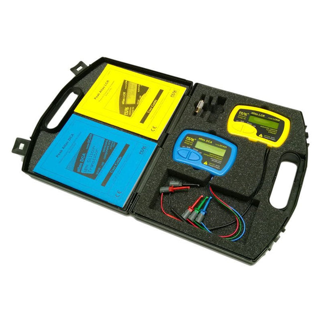
A fantastic dual instrument pack featuring the Atlas DCA Semiconductor Analyzer and the Atlas LCR Passive Component Analyzer. Housed in a robust padded case, complete with spare battery, user guide and space for accessories.
The LCR40 (for Inductors, Capacitors and Resistors) is ideal for the hobbyist and professional alike. The DCA55 (for most semiconductors) provides fast component identification, pinout identification and wide component support.
LCR40
Handheld LCR analyzer providing measurements for inductance, capacitance and resistance. The component type is automatically detected for you, just connect and press 'test'. The test frequency is automatically selected to provide the best measurement resolution. Test frequencies include DC, 1kHz, 15kHz and 200kHz. Inductance from 1uH to 10uH, minimum resolution of 1uH, typical accuracy of ±1.5% between 100uH and 100mH. Capacitance from 1pF to 10,000uF, minimum resolution of 1pF typical accuracy of ±1.5% between 200pF and 500nF. Resistance from 1R to 2MR, typical accuracy of ±1%. Test frequency is displayed with the measurement. Inductor DC resistance also displayed when testing inductors. Supplied with removable gold plated hook probes, battery and user guide. Compatible with standard 2mm test connectors. Not designed for in-circuit use.
Automatic component type detection: Inductor, Capacitor or Resistor
Automatic test frequency selection: DC, 1kHz, 15kHz and 200kHz
Inductance from 1uH to 10H
Capacitance from 1pF to 10,000uF
Resistance from 1Ohm to 2MOhm
Inductance measurement also shows DC winding resistance
Test frequency displayed for all measurements
Typical accuracy of 1.5% for inductors and capacitors (see spec table for details)
Typical accuracy of 1% for resistors
Test lead complete with gold plated 2mm plugs and sockets
Supplied with removable gold plated hook probes
DCA55
Connect any way round to automatically identify and measure a wide range of semiconductor devices. The DCA55 will automatically identify the type of the part, pinout and many component parameters. Components supported include bipolar NPN/PNP transistors, darlingtons, diode-protected transistors, transistors with built-in resistors, enhancement mode MOSFETs, depletion mode MOSFETs, diodes, diode networks, LEDs, 2 and 3 lead bicolour LEDs, JFETs and many more. Further measurements are displayed including transistor gain, leakage current, pn voltage drops, LED voltages, MOSFET threshold voltages and much more. Even if you don't know anything about the part, just connect it in any configuration and the DCA55 will identify the type of part for you and also identify all the leads. Supplied with universal gold plated hook probes, battery and illustrated user guide. Not designed for in-circuit testing.
Automatic pinout detection and identification, connect any way round
Automatic part type identification
Supports semiconductors including transistors, MOSFETs, diodes, LEDs, JFETs and much more
Detection of special component features such as transistors with diodes or transistors with built-in resistors
Transistor gain measurement
Transistor leakage measurement
MOSFET gate threshold measurement
Semiconductor voltage drop measurement
Supplied with gold plated red/green/blue universal hook probes
Included
Peak Atlas LCR40 Automatic Passive Component Analyzer
Peak Atlas DCA55 Semiconductor Analyzer
Extra GP23 Battery
Dual Carry Case