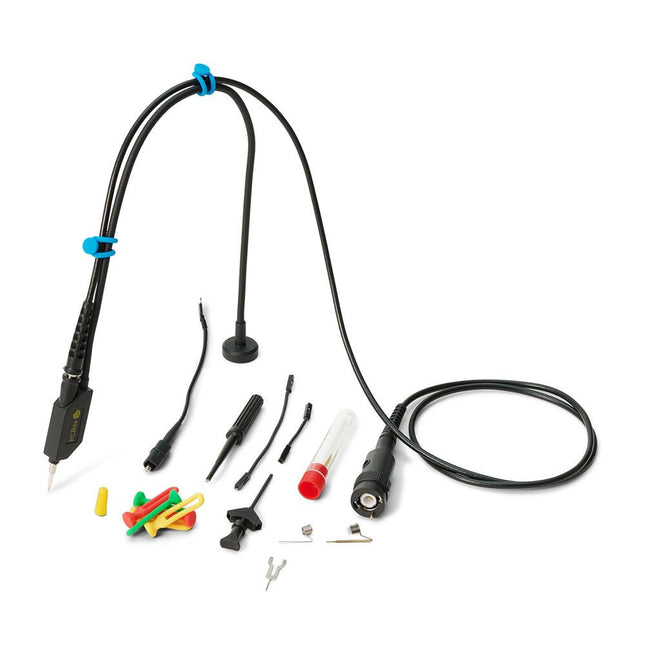
The SQ series of handsfree probes from Sensepeek have a lower point of gravity making them even more stable compared with the original SP series of handsfree probes. All probes in the SQ series are also insulated and can be used handheld as any traditional probe but their full potential is used when measuring handsfree.
The SQ series of oscilloscope probes also includes more ground options, have probe tip protection, longer cable and support for oscilloscopes with automatic scaling (10:1).
All the loved features of handsfree measurement, exchangeable fine pitch spring tipped test needle, color-coded cable holders and the minimalistic design is maintained to make traditional sized and handheld probes obsolete.
Both length and weight of the SQ probes are perfectly balanced to be used with PCBite PCB holders and base plate which is a must for handsfree function.
Features
Passive 10:1 probe with support for oscilloscopes with automatic scaling
Spring-loaded test needle for fine pitch measurements
Multiple ground options
Color coded cable holders
Probe tip protection
Insulated, can be used handheld
Improved probe holder for handsfree measurement when used with PCBite PCB holders
Included
1x SQ350 350 MHz probe with spring tipped test needle
1x SQ probe holder for handsfree measurement
1x Testhook with detachable cables (5 cm & 10 cm) for convenient ground connection
1x Alligator cable for convenient ground connection
1x Standard ground spring, for handheld measurements at rated bandwidth
1x Unique ground spring, for total handsfree measurements at rated bandwidth
1x Set of color coded cable holders (4 colors)
1x Probe tip protection
1x Extra test needle
Downloads
User Guide SQXX0 Rev1.1
The Sensirion SGP30 is a digital multi-pixel gas sensor that can easily integrate with air purifiers, demand-controlled ventilation, and other IoT applications. Powered by Sensirion’s CMOSens®technology, it integrates a complete sensor system on a single chip featuring a digital I2C interface, a temperature-controlled micro hotplate, and two preprocessed indoor air quality signals. As the first metal-oxide gas sensor featuring multiple sensing elements on one chip, the SGP30 provides more detailed information about air quality. Features Multi-pixel gas sensor for indoor air quality applications Outstanding long-term stability I2C interface with TVOC and CO2eq output signals Low power consumption Chip module tape and reel packaged, reflow solderable Specifications Weight: 9g Battery: Exclude Working Voltage: 3.3V/5V Output range: TVOC-0 ppb to 60000ppb / CO₂eq - 400 ppm to 60000 ppm Sampling rate: 1 Hz
Features Soil moisture sensor based on soil resistivity measurement Consists of two probes that allow the current to pass through the soil Easy to use and cost-effective Grove compatible interface( u-blox version) Specifications Dimensions: 60 x 20 x 6.35 mm
Weight: 10 g
Battery: Exclude
Operating voltage: 3.3 V ~ 5 V
Operating current: 35 mA
Sensor Output Value in dry soil: 0 ~ 300
Sensor Output Value in humid soil: 300 ~ 700
Sensor Output Value in water: 700 ~ 950
Pixel Pump is an open source vacuum pump for manual SMT assembly. It comes with a comfortable pen, a foot pedal, RGB LED buttons, and a variety of features that make hand assembly a lot more fun. It’s the perfect companion for manual SMT soldering applications, from individual prototypes to small production runs.
Thoughtful, High-Quality Design
Pixel Pump ships with a set of five stainless-steel nozzles in each of five different sizes, with outer diameters ranging from 0.3 mm all the way up to 1.8 mm. With this set, you should be able to pick and place most SMD components, including small 0402 passives, larger parts like inductors and ICs, and just about everything in between. The nozzles are held in place by a Luer lock slip fitting that facilitates quick nozzle changes and broad compatibility with third-party nozzles. The pen itself features a barbed connection for the air hose and incorporates four M8 steel nuts to give it some heft and to enable magnetic attachment to Pixel Pump.
Tactile silicone buttons with RGB backlighting offer full control over the unit. You can change operation modes, switch between high- and low-power settings, or activate reverse mode to clean your nozzle. The buttons also allow you to configure things like vacuum power and LED brightness.
Pixel Pump has a pressure-relief valve that dumps vacuum to ensure that your part gets released quickly when you release the foot pedal. Optionally, you can configure that valve to switch from suction mode to pressure mode, which quickly and easily cleans the nozzle in case you have accidentally sucked in debris like solder paste.
A sintered air filter protects the vacuum pump and valves from debris that might otherwise be sucked into the system. It is accessible from the outside and can easily be cleaned and reused.
A Perfect Companion For Prototype Boards & Small-Scale Manufacturing
Pixel Pump was designed primarily for individuals and organizations that manufacture one-off prototypes, but it’s also well suited for small production runs. It’s super easy to use and is actually faster than an automated pick-and-place machine for smaller batch sizes, especially when combined with SMD Magazines. Pixel Pump is the perfect companion for hobbyists and professionals who love making their own PCBs.
Features
Comfortable pen that accommodates various vacuum nozzles
Small, flexible, heat-resistant silicone hose that connects the pen to Pixel Pump
Magnetic base for the pen
Strong, adjustable vacuum, perfect for picking small and large components alike
Tactile, silicone RGB-button interface
Foot pedal for triggering the pump
Adjustable high/low power settings
Adjustable LED brightness
Reverse mode, which creates pressure instead of suction to clean nozzles
Vacuum relief valve for quick depressurization to drop parts more quickly
Easy software updates via USB Type-C
Compact design that respects the limited surface area of your workbench
Downloads
3D STL Files
Firmware
Mainboard Schematics
UI Board Schematics
Motor Controller Schematics
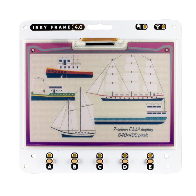
Inky Frame 4.0' features a vibrant E Ink display with 640 x 400 pixels of tightly packed seven colour goodness – that's almost as many pixels as on the 5.7' Inky Frame, but squished tidily into a smaller footprint. There's five buttons with LED indicators for interacting with the display, two Qw/ST connectors for plugging in breakouts and a micro SD card slot for storage of capybara photos or other vital files.
Every Inky Frame comes with a pair of sleek little metal legs so you can stand it up on your desk. There's also a battery connector so you can power it without annoying trailing wires, and some neato power saving features that mean you can run it from batteries for ages.
Inky Frame 4.0' is great for:
An ultra readable, low power consumption home automation dashboard
Displaying stylised photos, pop art images or favourite comic panels.
Showing cute graphs and readouts from local or wirelessly connected sensors
Displaying fascinating data from online APIs.
Features
Raspberry Pi Pico W Aboard
Dual Arm Cortex M0+ running at up to 133 Mhz with 264 kB of SRAM
2 MB of QSPI flash supporting XiP
Powered and programmable by USB micro-B
2.4 GHz wireless
4.01' EPD display (640 x 400 pixels)
E Ink Gallery Palette 4000 ePaper
ACeP (Advanced Color ePaper) 7-color with black, white, red, green, blue, yellow, orange.
Ultra wide viewing angles
Ultra low power consumption
Dot pitch – 0.135 x 0.135 mm
5x Tactile buttons with LED indicators
Two Qw/ST connectors for attaching breakouts
microSD card slot
Dedicated RTC chip (PCF85063A) for deep sleep/wake
Fully assembled (no soldering required)
C/C++ and MicroPython libraries
Schematic
Included
1x Inky Frame 4.0' (incl. Pico W)
2x Metal legs
Downloads
MicroPython
(Learn) Getting Started with Inky Frame
(Readme) Installing MicroPython
(Readme) MicroPython FAQs (and troubleshooting)
Download pirate-brand MicroPython (you'll want the Inky Frame.uf2)
MicroPython examples
PicoGraphics function reference
C/C++
C examples
Picographics function reference
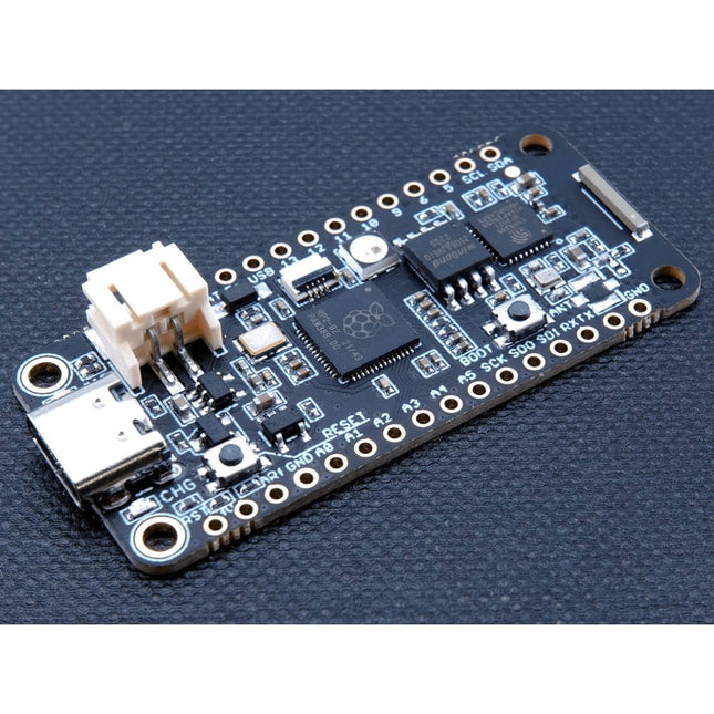
The Challenger RP2040 WiFi is a small embedded computer equipped with a WiFi module, in the popular Adafruit Feather form factor. It is based on an RP2040 microcontroller chip from the Raspberry Pi Foundation which is a dual-core Cortex-M0 that can run on a clock up to 133 MHz. The RP2040 is paired with a 8 MB high-speed flash capable of supplying data up to the max speed. The flash memory can be used both to store instructions for the microcontroller as well as data in a file system and having a file system available makes it easy to store data in a structured and easy to program approach. The device can be powered from a Lithium Polymer battery connected through a standard 2.0 mm connector on the side of the board. An internal battery charging circuit allows you to charge your battery safely and quickly. The device is shipped with a programming resistor that sets the charging current to 250 mA. This resistor can be exchanged by the user to either increase or decrease the charging current, depending on the battery that is being used. The WiFi section on this board is based on the Espressif ESP8285 chip which basically is a ESP8266 with 1 MB flash memory integrated onto the chip making it a complete WiFi only requiring very few external components. The ESP8285 is connected to the microcontroller using a UART channel and the operation is controlled using a set of standardized AT-commands. Specifications Microcontroller RP2040 from Raspberry Pi (133 MHz dual-core Cortex-M0) SPI One SPI channel configured I²C One I²C channel configured UART One UART channel configured (second UART is for the WiFi chip) Analog inputs 4 analog input channels WLAN controller ESP8285 from Espressif (160 MHz single-core Tensilica L106) Flash memory 8 MByte, 133 MHz SRAM memory 264 KByte (divided into 6 banks) USB 2.0 controller Up to 12 MBit/s full speed (integrated USB 1.1 PHY) JST Battery connector 2.0 mm pitch Onboard LiPo charger 250 mA standard charge current Onboard NeoPixel LED RGB LED Dimensions 51 x 23 x 3,2 mm Weight 9 g Downloads Datasheet Design files Product errata
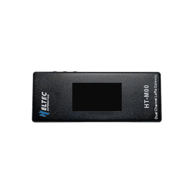
The HT-M00 is a dual-channel gateway that is specifically designed to cater to smart family LoRa applications that work with less than 30 LoRa nodes. The gateway has been built around two SX1276 chips that are driven by ESP32. To enable monitoring of 125 KHz SF7~SF12 spreading factor, a software mixer has been developed, which is commonly referred to as a baseband simulation program.
The software mixer is a critical component that enables the HT-M00 gateway to operate with high efficiency. It is designed to simulate baseband signals, which are then mixed with the radio frequency signals to produce the desired output. The software mixer has been developed with great care and precision, and has undergone rigorous testing to ensure that it is capable of delivering accurate and reliable results.
Features
ESP32 + SX1276
Emulates LoRa demodulators
Automatic adaptive spread spectrum factor, SF7 to SF12 for each channel is optional
Maximum output: 18 ±1dBm
Support for LoRaWAN Class A, Class C protocol
Specifications
MCU
ESP32-D0WDQ6
LoRa Chipset
SX1276
LoRa Band
863~870 MHz
Power Supply Voltage
5 V
Receiving Sensitivity
-110 dBm @ 300 bps
Interface
USB-C
Max. TX Power
17dB ±1dB
Operating Temperature
−20~70°C
Dimensions
30 x 76 x 14 mm
Included
1x HT-M00 Dual Channel LoRa Gateway
1x Wall bracket
1x USB-C cable
Downloads
Manual
Software
Documentation
Dragino LoRaWAN IoT Kit v3 is designed to facilitate beginners and developers to quickly learn and demonstrate LoRa/LoRaWAN and IoT technology. It helps users to turn the idea into a practical application and make the Internet of Things a reality. The LoRaWAN IoT Kit v3 can be used to evaluate the multi-channel LoRaWAN solution and single-channel private LoRa solution. Users can also use LoRaWAN IoT Kit v3 to test different network structure solutions and find the best for their IoT solution. The LoRaWAN IoT kit v3 shows how to build a LoRaWAN network, and how to use the network to send data from a LoRa sensor node to the cloud server. Depends on the actually use environment, the LoRaWAN gateway will connect your other LoRa nodes up to 500~5000 m. Features Open Source LoRa/LoRaWAN kits Support multi-channels LoRaWAN and Single-Channel LoRa Support various network structures Included 1x LPS8v2 LoRaWAN Gateway 1x LA66 LoRaWAN Shield for Arduino 1x LA66 USB LoRaWAN Adapter for PC/Mobile/RPi 1x DHT11 Temperature & Humidity Sensor 1x RGB LED 20x dupont cable (male to male) 20x dupont cable (female to female) 20x dupont cable (male to female) Downloads Datasheet Manual
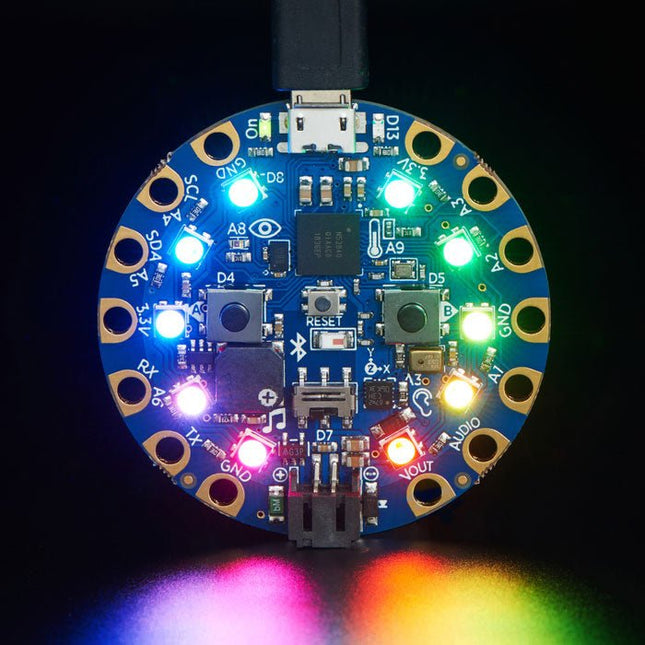
Circuit Playground Bluefruit is the third board in the Circuit Playground series, another step towards a perfect introduction to electronics and programming. Adafruit has taken the popular Circuit Playground Express and made it even better! Now the main chip is an nRF52840 microcontroller which is not only more powerful, but also comes with Bluetooth Low Energy support for wireless connectivity. The board is round and has alligator-clip pads around it so you don't have to solder or sew to make it work. You can power it from USB, a AAA battery pack, or with a Lipoly battery (for advanced users). Circuit Playground Bluefruit has built-in USB support. Built in USB means you plug it in to program it and it just shows up, no special cable or adapter required. Just program your code into the board then take it on the go! Features 1x nRF52840 Cortex M4 processor with Bluetooth Low Energy support 10x mini NeoPixels, each one can display any color 1x Motion sensor (LIS3DH triple-axis accelerometer with tap detection, free-fall detection) 1x Temperature sensor (thermistor) 1x Light sensor (phototransistor). Can also act as a color sensor and pulse sensor. 1x Sound sensor (MEMS microphone) 1x Mini speaker with class D amplifier (7.5 mm magnetic speaker/buzzer) 2x Push buttons, labeled A and B 1x Slide switch 8x alligator-clip friendly input/output pins Includes I²C, UART, 6 pins that can do analog inputs, multiple PWM outputs Green 'ON' LED so you know its powered Red '#13' LED for basic blinking Reset button 2 MB of SPI Flash storage, used primarily with CircuitPython to store code and libraries. MicroUSB port for programming and debugging USB port can act like serial port, keyboard, mouse, joystick or MIDI! Specifications Outer Diameter: ~50.6 mm / ~2.0' Weight: 8.9 g
The Waveshare ESP32-S3 4" Capacitive Touch Display is a microcontroller development board featuring 2.4 GHz WiFi and BLE 5 support. It integrates 16 MB of Flash and 8 MB of PSRAM. The onboard 4-inch 480 x 480 capacitive touch screen is capable of running GUI programs smoothly, such as those developed with LVGL.
With its versatile peripheral interfaces, the board enables quick development of HMI (Human-Machine Interface) applications based on the ESP32-S3. It is suitable for a variety of scenarios, including: Smart control panels, Home gateways, Intelligent interactive panels, Industrial control systems, Smart lighting control.
Specifications
Processor
High performance Xtensa 32-bit LX7 dual-core processor, with a main frequency of up to 240 MHz
Wi-Fi/Bluetooth
Supports 2.4 GHz Wi-Fi (802.11 b/g/n) and Bluetooth 5 (LE), with an onboard antenna
Flash/PSRAM
16 MB Flash + 8 MB PSRAM
Power Supply
USB-C (5 V) + DC (7-36 V)
Resolution
480 x 480
Display Interface
RGB
Display Panel
IPS
Viewing Angle
160°
Touch Type
Capacitive
Touch Panel
Toughened Glass
Communication Interfaces
CAN, RS485, I²C, USB
Dimensions
84.2 x 84.2 mm
Included
1x ESP32-S3 4-inch Capacitive Touch Display Dev Board (ESP32-S3-Touch-LCD-4)
1x Back wiring 3.5 mm pitch 10P pluggable terminal block
1x Bottom wiring 3.5 mm pitch 10P pluggable terminal block
Downloads
Wiki
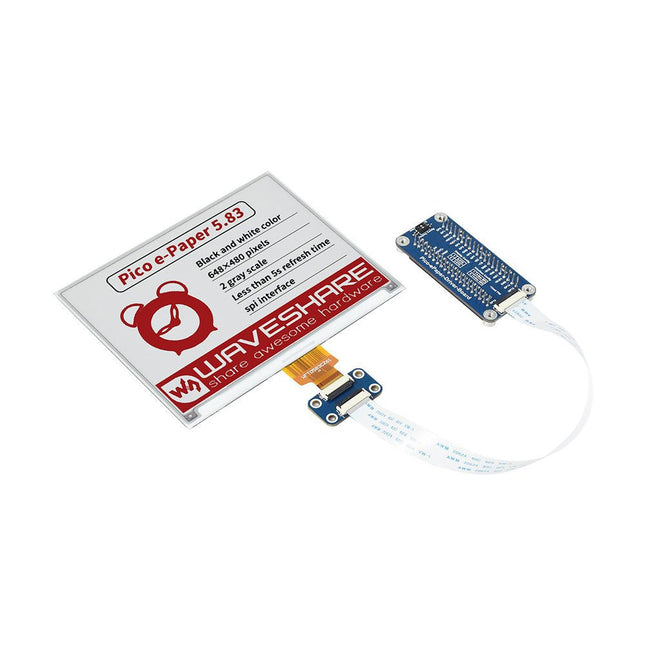
This 5.83-inch 3-color e-paper e-ink display module for Raspberry Pi Pico offers a resolution of 648 × 480 pixels, an SPI interface, low power consumption, wide viewing angle and a paper-like effect without electricity.
Features
No backlight, keeps displaying last content for a long time even when power down
Ultra low power consumption, basically power is only required for refreshing
SPI interface, requires minimal I/O pins
2x user buttons and 1x reset button for easy interacting
Comes with development resources and manual (Raspberry Pi Pico C/C++ and MicroPython examples)
Specifications
Operating voltage
3.3 V
Display color
Red, black, white
Resolution
648 × 480 pixels
Gray scale
2
Interface
3-wire SPI, 4-wire SPI
Viewing angle
>170°
Partial refresh time
N/A
Full refresh time
5s
Outline dimensions
125.4 × 99.5 mm
Display size
119.232 × 88.320 mm
Refresh power
26.4 mW (typ.)
Standby current
<0.01 uA (almost none)
Dot pitch
0.184 × 0.184 mm
Applications
Suitable For Price Tags
Asset/Equipment Tags
Shelf Labels
Conference Name Tag
Included
1x 5.83-inch e-Paper (B)
1x Pico-ePaper-Driver-Board
1x Standoff pack
Downloads
Wiki
This set contains 3 nozzles for Hot Air Rework Stations such as ZD-8922 or ZD-8968.
Included
1x Hot air nozzle 79-3911
1x Hot air nozzle 79-3912
1x Hot air nozzle 79-3913
The SparkFun RP2040 mikroBUS Development Board is a low-cost, high performance platform with flexible digital interfaces featuring the Raspberry Pi Foundation's RP2040 microcontroller. Besides the Thing Plus or Feather PTH pin layout, the board also includes a microSD card slot, 16 MB (128 Mbit) flash memory, a JST single cell battery connector (with a charging circuit and fuel gauge sensor), an addressable WS2812 RGB LED, JTAG PTH pins, four (4-40 screw) mounting holes, our signature Qwiic connectors, and a mikroBUS socket. The mikroBUS standard was developed by MikroElektronika. Similar to Qwiic and MicroMod interfaces, the mikroBUS socket provides a standardized connection for add-on Click boards to be attached to a development board and is comprised of a pair of 8-pin female headers with a standardized pin configuration. The pins consist of three groups of communications pins (SPI, UART and I²C), six additional pins (PWM, Interrupt, Analog input, Reset and Chip select), and two power groups (3.3 V and 5 V). The RP2040 is supported with both C/C++ and MicroPython cross-platform development environments, including easy access to runtime debugging. It has UF2 boot and floating-point routines baked into the chip. While the chip has a large amount of internal RAM, the board includes an additional 16 MB of external QSPI flash memory to store program code. The RP2040 contains two ARM Cortex-M0+ processors (up to 133 MHz) and features: 264 kB of embedded SRAM in six banks 6 dedicated IO for SPI Flash (supporting XIP) 30 multifunction GPIO: Dedicated hardware for commonly used peripherals Programmable IO for extended peripheral support Four 12-bit ADC channels with internal temperature sensor (up to 0.5 MSa/s) USB 1.1 Host/Device functionality Features (SparkFun RP2040 mikroBUS Dev. Board) Raspberry Pi Foundation's RP2040 microcontroller 18 Multifunctional GPIO Pins Four available 12-bit ADC channels with internal temperature sensor (500kSa/s) Up to eight 2-channel PWM Up to two UARTs Up to two I²C buses Up to two SPI buses Thing Plus (or Feather) Pin Layout: 28 PTH Pins USB-C Connector: USB 1.1 Host/Device functionality 2-pin JST Connector for a LiPo Battery (not included): 500mA charging circuit 4-pin JST Qwiic Connector LEDs:
PWR - Red 3.3V power indicator
CHG - Yellow battery charging indicator
25 - Blue status/test LED (GPIO 25)
WS2812 - Addressable RGB LED (GPIO 08) Buttons: Boot Reset JTAG PTH Pins 16MB QSPI Flash Memory µSD Card Slot mikroBUS Socket Dimensions: 3.7' x 1.2' Four Mounting Holes: 4-40 screw compatible Downloads Schematic Eagle Files Board Dimensions Hookup Guide Qwiic Info Page GitHub Hardware Repository
This PCIe 3.0 to dual M.2 HAT enables the Raspberry Pi 5 to access two NVMe SSDs, Hailo-8/8L (M.2 key B+M only), and Google Coral AI accelerators at PCIe 3.0 speeds.
Features
Dual M.2 Slots with PCIe 3.0 Speed: Utilizes the ASMedia ASM2806 PCIe 3.0 switch chip to ensure optimal performance, overcoming the limitations of PCIe 2.0.
Stable Power Supply: Additional pogo pins provide extra power to ensure a stable high-speed connection.
Multiple Size Support: Compatible with M.2 standard sizes 2230, 2242, 2260, and 2280.
Back-mounted Design: Keeps the 40-pin GPIO free for use, allowing compatibility with other Raspberry Pi HATs.
User-friendly Design: The S-shaped FPC cable does not obstruct the microSD card slot.
Open Source Case: Seeed’s M.2 HATs are not compatible with the official Raspberry Pi case, but an adapted 3D-printable case (STP file) is provided.
Applications
Simultaneously supports AI acceleration and high-speed SSD storage
Connects dual NVMe SSDs for large storage capacity
Booting a Raspberry Pi from the SSD
Specifications
M.2 Slots
2
Max. PCIe Speed
PCIe Gen3.0
PCIe Switch Chip
ASM2806
M.2 Size Support
2280/2260/2242/2230
Max. Power Supply
5 V/3 A (max 3A: Pogo pin 2A + PCIe connector 1A)
Cable
FPC
Assembly Method
Back installation
Dimensions
87 x 55 x 10 mm
Included
1x Seeed Studio PCIe 3.0 to Dual M.2 HAT for Raspberry Pi 5
2x FPC cables (50 mm)
1x Screws & stud pack
Downloads
Wiki
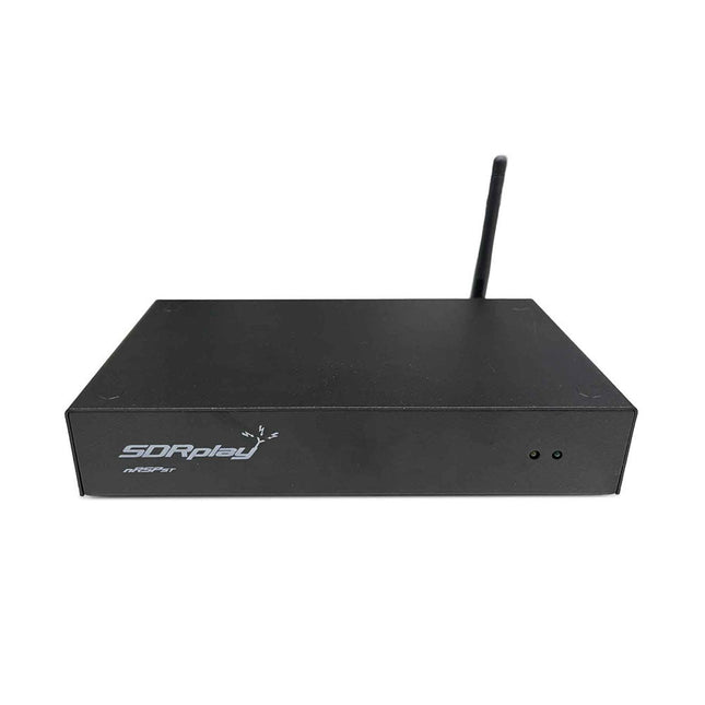
The nRSP-ST is a networked general coverage radio receiver for frequencies from 1 kHz to 2 GHz with up to 10 MHz of spectrum visibility. The nRSP-ST is your own personal remotely accessible SDR which can also be shared with a small number of trusted friends or colleagues.
The nRSP-ST addresses the needs of radio enthusiasts who want a 'plug-and-play' solution for remote reception. As well as achieving this, we have addressed typical internet bandwidth limitations with the creation of a novel IQ Lite mode, which efficiently delivers channels of IQ data. We are also introducing the ability to control and store IQ recordings at the remote location. The nRSP-ST is ideal for anyone wanting a wideband remote receiver without needing computer skills and hours of set-up time and ongoing maintenance at the remote location.
Features
"Plug and play" integrated, networked general coverage receiver:
Combines a receiver, a host computer and a whole lot more – all in one box!
Apply power and connect to the internet (Ethernet or Wi-Fi) and the nRSP-ST is automatically accessible from anywhere
Multi-platform SDRconnectTM software supports local operation or remote access on Windows, MacOS or Linux platforms
The nRSP-ST & SDRconnect are configurable for available network bandwidth:
In Full IQ mode, the nRSP-ST provides IQ data transfer of the visible spectrum bandwidth (e.g. for high-speed LAN or superfast internet connectivity)
In IQ Lite mode, the nRSP-ST provides IQ data of channels up to 192 kHz wide (e.g. for digital decoding by the client)
In Compact mode the nRSP-ST provides compressed audio (ideal for slower internet connections)
Supports multiple client connections with a simultaneous mixture of connection modes – an admin tool allows you to assign usernames and timeouts to trusted friends or colleagues.
All modes support visualization of up to 10 MHz spectrum bandwidth
Two remote connection options:
Use a remote SDRconnect client or
Use the built-in web-server for remote access from any web browsing capable device, including Android/iOS tablets and phones
The nRSP-ST offers the ability to record IQ and audio files to a NAS (network attached storage) device if available on the LAN.
The 14-bit ADC full featured wideband SDR receiver covers all frequencies from 1 kHz through VLF, LF, MW, HF, VHF, UHF and L-band to 2 GHz, with no gaps
Remotely monitor up to 10 MHz of spectrum at a time from a choice of 3 antennas
Flash upgradable for future feature enhancements
Included
1x nRSP-ST Receiver
1x WLAN antenna
1x Power supply
1x Manual
Downloads
Release notes
Software
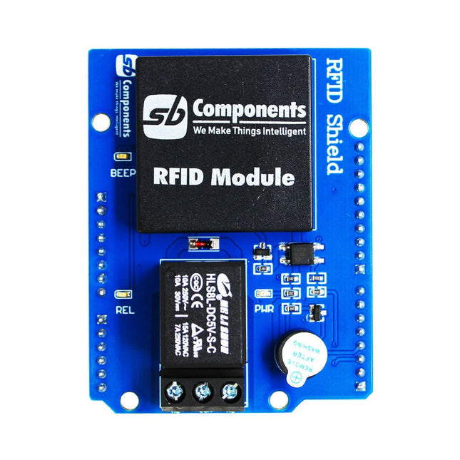
Designed with convenience and security in mind, the Ardi RFID Shield is based on the EM-18 module, operating at a frequency of 125 KHz. This shield allows you to easily integrate RFID (Radio Frequency Identification) technology into your projects, enabling seamless identification and access control systems.
Equipped with a powerful 1-channel optoisolated relay, the Ardi RFID Shield offers a reliable switching solution with a maximum DC rating of 30 V and 10 A, as well as an AC rating of 250 V and 7 A. Whether you need to control lights, motors, or other high-power devices, this shield provides the necessary functionality.
Additionally, the Ardi RFID Shield features an onboard buzzer that can be utilized for audio feedback, allowing for enhanced user interaction and system feedback. With the onboard 2-indication LEDs, you can easily monitor the status of RFID card detection, power supply, and relay activation, providing clear visual cues for your project's operation.
Compatibility is key, and the Ardi RFID Shield ensures seamless integration with the Arduino Uno platform. Paired with a read-only RFID module, this shield opens up a world of possibilities for applications such as access control systems, attendance tracking, inventory management, and more.
Features
Onboard 125 kHz EM18 RFID small, compact module
Onboard High-quality relays Relay with Screw terminal and NO/NC interfaces
Shield compatible with both 3.3 V and 5 V MCU
Onboard 3 LEDs power, relay ON/OFF State and RFID Scan status
Multi-tone Buzzer onboard for Audio alerts
Mounts directly onto ArdiPi, Ardi32 or other Arduino compatible boards
Specifications
RFID operating Frequency: 125 kHz
Reading distance: 10 cm, depending on TAG
Integrated Antenna
Relay Max Switching Voltage: 250 V AC/30 V DC
Relay Max Switching Current: 7 A/10 A
Features Operate voltage: 3.3 V - 5 V Input current: 100mA Rated load: 5 A @ 250 VAC, 5 A @ 30 VDC Contact resistance: 50 mΩ @ 6 VDC 1 A Insulation resistance: 100 MΩ 10 ms Max. Operate time: 10 ms Max. Release time: 5 ms Max. Input interface: Digital Dimensions: 42 mm x 24 mm x 18.5 mm Included 1 x Grove Relay 1 x User Guide Downloads Grove Relay Schematics
The QA451 is designed for high-speed testing of amplifiers. If you are testing at the module level (with modules designed for single supply operation), the QA451 allows the on/off control and current measurement of the supply rail. The QA451 is a companion product to the QA403 Audio Analyzer. When combined, the products work together to ensure fast, repeatable automated measurements of audio power amplifiers up to several hundred watts.
Features
Programmable 4/8 Ω load
Fully isolated from PC
USB powered
Up to 200 W for 220 mS
DC Current Sensing
Integrated 6th order LPF
REST Interface
The QA451 can be controlled manually from a PC application or controlled using a web-based REST interface.
Measuring Current
The QA451 allows low-cost external fixed-voltage supplies to be used to power your amplifier during test – dramatically reducing your investment per test bay. The QA451 integrates a high-side switch, enabling on/off control of the supply to the amplifier. When turning on the supply, a momentary soft-start circuit ensures the amplifier-under-test isn’t exposed to high currents that might overstress components. And during operation, the QA451 provides an isolated current measurement, allowing up to 15 A (peak) of DC current to be measured with 10-20 mA of resolution. This permits automated efficiency measurements to be easily made – a primary predictor of whether the amplifier was assembled correctly.
4 and 8 Ω Loads
The QA451 provides both 4 and 8 ohm resistive loads. The loads are thermally protected using fast, high-accuracy digital thermal sensors ensuring that fault conditions won’t damage the QA451.
Downloads
Datasheet
Wiki
Software
The Tabloid/A3 size Magnetic Easel is a sturdy work-holding tool that provides an alternative method of positioning paper or other workpieces for use with the AxiDraw V3/A3 and AxiDraw SE/A3. A heavy-duty alternative to the regular A3 clip easel, it can be used with binder clips or the (included) positioning rulers, magnets, and magnetic spring clips. The base of the easel is a heavy-gauge sheet of magnetic steel. It has a powder-coat finish, lightly textured to help hold paper in place and light gray in color for visible contrast against most types of paper. Rubber bumpers on the bottom side (along with the substantial weight of the steel) ensure a no-slip grip on your work table. To help index your paper in a consistent and reproducible position, the easel includes two six-inch (15 cm) rulers that you can rest your paper up against. The rulers are easy to remove and reversible, with inch and centimeter markings on the two sides. They can also be removed completely if you like, leaving just a flat sheet of steel (with a few ruler-mounting holes in it). This A3 easel also includes a special set of paper holding clips and magnets: Two special spring clips with magnetic bases, plus six skinny magnets for holding down paper. The two special spring clips each have two curved tines that apply gentle pressure to your paper. They allow you to slide paper directly in and out, quickly and easily, without touching any magnets, clips, or tape. They have a long reach to be positioned behind the rulers, or elsewhere if you prefer. Magnetic bases allow you to position them where needed. Two of these spring clips provide just enough pressure to keep a sheet of paper steady while you write or draw on it. This set also includes six cylindrical magnets, 4 mm in diameter and 10 mm tall, which are easy to position and firmly hold paper. The tall aspect ratio makes them particularly easy to grasp (unlike disc magnets). Perhaps more importantly, they tend to yield and tip over if hit by an errant pen tip, rather than holding so fast as to damage your pen or move your paper. Overall dimensions: 18.12 x 12.72' (46.0 x 32.3 cm) Suitable for use with A3 and US Tabloid/Ledger paper sizes, envelopes, two sheets of Letter or A4 paper, or smaller sizes of paper.
The board's main processor is a low-power Arm® Cortex®-M0 32-bit SAMD21. The WiFi and Bluetooth® connectivity is performed with a module from u-blox, the NINA-W10, a low-power chipset operating in the 2.4GHz range. On top of that, secure communication is ensured through the Microchip® ECC608 crypto chip. Besides that, you can find a 6 axis IMU, which makes this board perfect for simple vibration alarm systems, pedometers, the relative positioning of robots, etc. WiFi and Arduino IoT Cloud You can get your board to connect to any kind of existing WiFi network, or use it to create your own Arduino Access Point. The specific set of examples we provide for the Nano 33 IoT can be consulted at the WiFiNINA library reference page. It is also possible to connect your board to different Cloud services, Arduino's own among others. Here are some examples of how to get the Arduino boards to connect to:
Arduino's own IoT Cloud: Arduino's IoT Cloud is a simple and fast way to ensure secure communication for all of your connected Things. Check it out here.
Blynk: a simple project from our community connecting to Blynk to operate your board from a phone with little code.
IFTTT: see an in-depth case of building a smart plug connected to IFTTT.
AWS IoT Core: we made this example on how to connect to Amazon Web Services.
Azure: visit this GitHub repository explaining how to connect a temperature sensor to Azure's Cloud.
Firebase: you want to connect to Google's Firebase, this Arduino library will show you how. Microcontroller SAMD21 Cortex®-M0+ 32bit low power ARM MCU Radio Module u-blox NINA-W102 Secure Element ATECC608A Operating Voltage 3.3 V Input Voltage 21 V Digital I/O Pins 14 PWM Pins 11 DC Current per I/O Pin 7 mA Analog Input Pins 8 Analog Output Pins 1 External Interrupts all digital pins UART 1 SPI 1 I2C 1 Flash Memory 256 KB SRAM 32 KB EEPROM none Clock Speed 48 MHz LED_Builtin 13 USB Native in the SAMD21 Processor IMU LSM6DS3 Length 45 mm Width 18 mm Weight 5 g
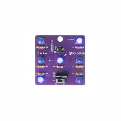
If you are looking for an easy way to get started with soldering or simply want to make a small portable gadget, this set is a great opportunity. "LED cube" is an educational set for learning the soldering skill, with which you get a small electronic game at the end. After you turn on and shake this board, certain leds will light up randomly and symbolize the number, as if a real die had been thrown.
It is based on the Attiny404 microcontroller, programmed in Arduino, and there is a battery on the back which makes this gadget portable. There is also a keychain so you can always carry your new game with you! Soldering is easy according to the markings on the board.
Included
1x PCB
1x ATtiny404 microcontroller
7x LEDs
7x Resistors (330 ohm)
1x Resistor (10 kohm)
1x Battery holder
1x CR2032 battery
1x Switch
1x Vibration sensor SW-18020P
1x Keychain ring
These are some of our favourite sensors from each category. But wait, there's more! The SparkFun Sensor Kit now includes several of our sensor boards that feature the Qwiic Connect System for rapid prototyping!
This version of the kit has received a complete overhaul!
This huge assortment of sensors makes an amazing gift for that exceptional electronics enthusiast in your life!
Included
Large Piezo Vibration Sensor (With Mass): A flexible film able to sense for vibration, touch, shock, etc. When the film moves back and forth an AC wave is created, with a voltage of up to ±90.
Reed Switch: Senses magnetic fields, makes for a great non-contact switch.
0.25' Magnet Square: Plays nicely with the reed switch. Embed the magnet into stuffed animals or inside a box to create a hidden actuator to the reed switch.
0.5' Force Sensitive Resistor: A force-sensing resistor with a 0.5' diameter sensing area. Great for sensing pressure (i.e., if it's being squeezed).
Flex Sensor (2.2'): As the sensor is flexed, the resistance across the sensor increases. Useful for sensing motion or positioning.
SoftPot: These are very thin variable potentiometers. By pressing on various positions along the strip, you vary the resistance.
Mini Photocell: The photocell will vary its resistance based on how much light it's exposed to. Will vary from 1kΩ in the light to 10kΩ in the dark.
PIR Motion Sensor: Easy-to-use motion detector with an analog interface. Power it with 5-12VDC, and you'll be alerted of any movement.
QRD1114 Optical Detector/Phototransistor: An all-in-one infrared emitter and detector. Ideal for sensing black-to-white transitions or can be used to detect nearby objects.
IR Diode: This LED can handle up to 50mA of current and outputs in the 940-950nm IR spectrum. Use to send signal to talk to the included IR receiver diode or just turn off your neighbor's TV.
IR Receiver Diode: This simple IR receiver will detect an IR signal coming from a standard IR remote control or the IR diode included in the kit.
Resistor 1.0M Ohm 1/4 Watt PTH: Two 1/4 Watt, +/- 5% tolerance PTH resistors. Commonly used in breadboards and perf boards. The large resistor helps dampen any voltage spikes when using the large piezo vibration sensor with a microcontroller.
Resistor 10K Ohm 1/4 Watt PTH – 20 pack (Thick Leads): 1/4 Watt, +/- 5% tolerance PTH resistors. Commonly used in breadboards and perf boards, these 10KΩ resistors make excellent pullups, pulldowns, and current limiters.
Resistor 330 Ohm 1/4 Watt PTH – 20 pack (Thick Leads): 1/4 Watt +/- 5% tolerance PTH resistors. Commonly used in breadboards and perf boards, these 330Ω resistors make excellent current-limiting resistors for LEDs.
SparkFun 9DoF IMU Breakout – ISM330DHCX, MMC5983MA (Qwiic): This breakout board includes a 3-axis accelerometer, 3-axis gyroscope, and 3-axis magnetometer. Connect this board over I2C using a Qwiic cable or solder wires or headers to the SPI pins to get started using one of the three sensors or using all three together to determine 3D orientation.
SparkFun Atmospheric Sensor Breakout – BME280 (Qwiic): The SparkFun BME280 Atmospheric Sensor Breakout is an easy way to measure barometric pressure, humidity, and temperature readings, all without taking up too much space.
SparkFun Indoor Air Quality Sensor – ENS160 (Qwiic): The SparkFun ENS160 Indoor Air Quality Sensor is a digital multi-gas sensor solution with four sensor elements that can be used in a wide range of applications including building automation, smart home, and HVAC.
SparkFun Capacitive Touch Slider – CAP1203 (Qwiic): This little board acts great as a non-mechanical button. Use the three pads on the board or connect your own input for a great touch button or slider with no moving parts.
Flexible Qwiic Cable (100 mm): Use these to connect up to four Qwiic boards in your kit.
RGB and Gesture Sensor (APDS-9960): This board does a little bit of everything. You can measure ambient light or color as well as detect proximity and do gesture sensing all over I2C.
Soil Moisture Sensor (with screw terminals): Ever wonder if your plant needs water? This sensor outputs an analog signal based on the resistance of the soil. Since water is conductive, the soil water content will be reflected in the soil resistance.
Sound Detector: Ever need to know if there is noise in an area? This board will not only tell you, but it will also output amplitude as well as the full audio signal.
Break Away Headers (Straight): Solder these pins to any of the breakouts to prototype on a breadboard. You'll want to solder these to boards that do not have Qwiic connectors such as the gesture sensor and sound detector.
The SparkFun Weather Shield uses the Si7021 humidity / temperature sensor, the MPL3115A2 barometric pressure sensor, and the ALS-PT19 light sensor. The shield utilizes the MPL3115A2 and Si7021 Arduino libraries.
The SparkFun Weather Shield comes with two unpopulated RJ11 connector spaces and a 6-pin GPS connector. Finally, each Weather Shield can operate from 3.3 V up to 16 V and has built-in voltage regulators and signal translators.
Check out the GitHub page, Schematics, and Eagle Files for more information.
Pico Cube is a 4x4x4 LED cube HAT for Raspberry Pi Pico with 5 VDC operating voltage. Pico cube, a monochromatic Red with 64 LEDs, is a fun way to learn programming. It is designed to perform incandescent operations with low energy consumptions, robust outlook, and easy installation that make people/kids/users learn the effects of LED lights with a different pattern of colors via the combination of software and hardware i.e. Raspberry Pi Pico.
Features
Standard 40 Pins Raspberry Pi Pico Header
GPIO Based Communication
64 High-Intensity Monochromatic LEDs
Individual LED access
Each Layer Access
Specifications
Operating Voltage: 5 V
Color: Red
Communication: GPIO
LEDs: 64
Included
1x Pico Cube Base PCB
4x Layer PCB
8x Pillar PCB
2x Male Berg (1 x 20)
2x Female Berg (1 x 20)
70 LEDs
Note: Raspberry Pi Pico is not included.
Downloads
GitHub
Wiki