The SparkFun RedBoard Qwiic is an Arduino-compatible board that combines features of different Arduinos with the Qwiic Connect System.
Features
ATmega328 microcontroller with Optiboot Bootloader
R3 Shield Compatible
CH340C Serial-USB Converter
3.3 V to 5 V Voltage Level Jumper
A4 / A5 Jumpers
AP2112 Voltage Regulator
ISP Header
Input voltage: 7 V - 15 V
1 Qwiic Connector
16 MHz Clock Speed
32 k Flash Memory
All SMD Construction
Improved Reset Button
Plug a reader into the headers, use a Qwiic cable, scan your 125kHz ID tag, and the unique 32-bit ID will be shown on the screen. The unit comes with a read LED and buzzer, but don't worry, there is a jumper you can cut to disable the buzzer if you want. Utilizing SparkFun's handy Qwiic system, no soldering is required to connect it to the rest of your system. However, we still have broken out 0.1"-spaced pins if you prefer to use a breadboard.
Utilizing the onboard ATtiny84A, the Qwiic RFID takes the six byte ID tag of your 125kHz RFID card, attaches a timestamp to it, and puts it onto a stack that holds up to 20 unique RFID scans at a time. This information is easy to get at with some simple I²C commands.
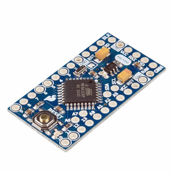
The Arduino Pro Mini is a microcontroller board based on the ATmega328P.
It has 14 digital input/output pins (of which 6 can be used as PWM outputs), 6 analog inputs, an on-board resonator, a reset button, and holes for mounting pin headers. A six pin header can be connected to an FTDI cable or SparkFun breakout board to provide USB power and communication to the board.
The Arduino Pro Mini is intended for semi-permanent installation in objects or exhibitions. The board comes without pre-mounted headers, allowing the use of various types of connectors or direct soldering of wires. The pin layout is compatible with the Arduino Mini.
The Arduino Pro Mini was designed and is manufactured by SparkFun Electronics.
Specifications
Microcontroller
ATmega328P
Board Power Supply
5-12 V
Circuit Operating Voltage
5 V
Digital I/O Pins
14
PWM Pins
6
UART
1
SPI
1
I²C
1
Analog Input Pins
6
External Interrupts
2
DC Current per I/O Pin
40 mA
Flash Memory
32 KB of which 2 KB used by bootloader
SRAM
2 KB
EEPROM
1 KB
Clock Speed
16 MHz
Dimensions
18 x 33.3 mm (0.7 x 1.3")
Downloads
Eagle files
Schematics
Maker Line is a line sensor with 5 x IR sensors array that is able to track line from 13 mm to 30 mm width.
The sensor calibration is also simplified. There is no need to adjust the potentiometer for each IR sensor. You just have to press the calibrate button for 2 seconds to enter calibration mode. Afterwards you need to sweep the sensors array across the line, press the button again and you are good to go.
The calibration data is saved in EEPROM and it will stay intact even if the sensor has been powered off. Thus, calibration only needs to be carried out once unless the sensor height, line color or background color has changed.
Maker Line also supports dual outputs: 5 x digital outputs for the state of each sensor independently, which is similar to conventional IR sensor, but you get the benefit of easy calibration, and also one analog output, where its voltage represents the line position. Analog output also offers higher resolution compared to individual digital outputs. This is especially useful when high accuracy is required while building a line following robot with PID control.
Features
Operating Voltage: DC 3.3 V and 5 V compatible (with reverse polarity protection)
Recommended Line Width: 13 mm to 30 mm
Selectable line color (light or dark)
Sensing Distance (Height): 4 mm to 40 mm (Vcc = 5 V, Black line on white surface)
Sensor Refresh Rate: 200 Hz
Easy calibration process
Dual Output Types: 5 x digital outputs represent each IR sensor state, 1 x analog output represents line position.
Support wide range of controllers such as Arduino, Raspberry Pi etc.
Downloads
Datasheet
Tutorial: Building A Low-Cost Line Following Robot
Principles, Systems, and Electronics
This handbook provides a detailed study of the sensors and actuators at the heart of modern vehicle electronics. It begins with basic electrical and electronic concepts, introducing the principles and terminology essential for understanding automotive systems.
The book explores sensors and actuators on a system-by-system basis, including:
Fundamentals of electrical engineering, electromagnetic phenomena, and motor principles
Passive and active electronic components, integrated circuits, protection devices, and automotive-grade electronics
Sensor characteristics, signal conditioning, ADCs, PWM and frequency outputs, and interface adaptation
Automotive communication links and protocols, including LIN and SENT
Engine sensors: air mass, pressure, temperature, speed, position, exhaust and emissions-related sensors
Transmission sensors for manual and automatic systems
Steering and suspension sensors for conventional and active systems
Vehicle body and electrical system sensors for comfort, climate, access, and monitoring functions
Engine actuators such as throttle bodies, injectors, turbo actuators, EGR systems, ignition components, and pumps
Transmission, brake, steering, suspension, and body actuators
Identification and coding of electronic components and packages commonly used in automotive applications
The structure and operating principles of each component are explained, with relevant electronic circuitry illustrated. Its system-oriented organization and practical focus make it a valuable reference for understanding, testing, and troubleshooting automotive electronic systems.
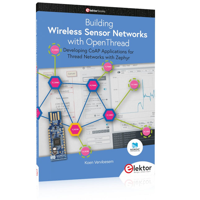
Developing CoAP applications for Thread networks with Zephyr
This book will guide you through the operation of Thread, the setup of a Thread network, and the creation of your own Zephyr-based OpenThread applications to use it. You’ll acquire knowledge on:
The capture of network packets on Thread networks using Wireshark and the nRF Sniffer for 802.15.4.
Network simulation with the OpenThread Network Simulator.
Connecting a Thread network to a non-Thread network using a Thread Border Router.
The basics of Thread networking, including device roles and types, as well as the diverse types of unicast and multicast IPv6 addresses used in a Thread network.
The mechanisms behind network discovery, DNS queries, NAT64, and multicast addresses.
The process of joining a Thread network using network commissioning.
CoAP servers and clients and their OpenThread API.
Service registration and discovery.
Securing CoAP messages with DTLS, using a pre-shared key or X.509 certificates.
Investigating and optimizing a Thread device’s power consumption.
Once you‘ve set up a Thread network with some devices and tried connecting and disconnecting them, you’ll have gained a good insight into the functionality of a Thread network, including its self-healing capabilities. After you’ve experimented with all code examples in this book, you’ll also have gained useful programming experience using the OpenThread API and CoAP.
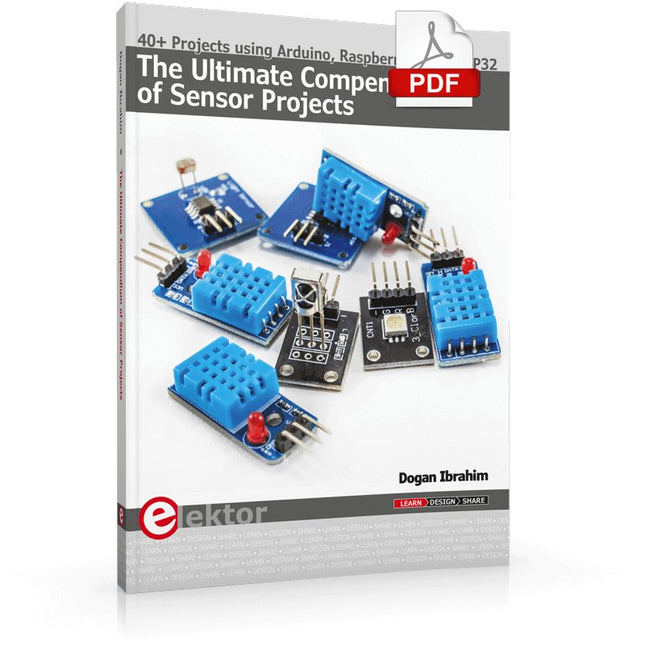
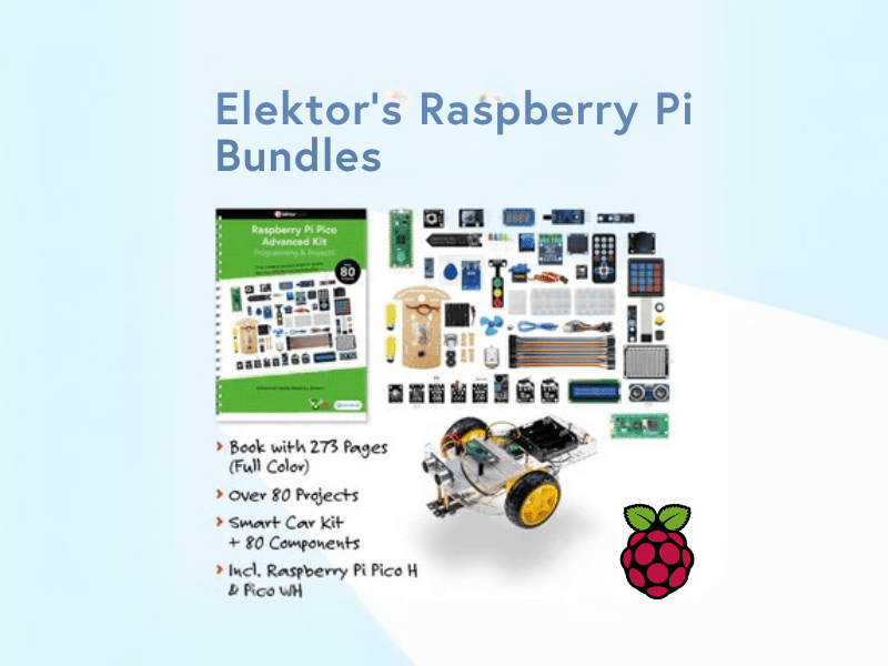
40+ Projects using Arduino, Raspberry Pi and ESP32
This book is about developing projects using the sensor-modules with Arduino Uno, Raspberry Pi and ESP32 microcontroller development systems. More than 40 different sensors types are used in various projects in the book. The book explains in simple terms and with tested and fully working example projects, how to use the sensors in your project. The projects provided in the book include the following:
Changing LED brightness
RGB LEDs
Creating rainbow colours
Magic wand
Silent door alarm
Dark sensor with relay
Secret key
Magic light cup
Decoding commercial IR handsets
Controlling TV channels with IT sensors
Target shooting detector
Shock time duration measurement
Ultrasonic reverse parking
Toggle lights by clapping hands
Playing melody
Measuring magnetic field strength
Joystick musical instrument
Line tracking
Displaying temperature
Temperature ON/OFF control
Mobile phone-based Wi-Fi projects
Mobile phone-based Bluetooth projects
Sending data to the Cloud
The projects have been organized with increasing levels of difficulty. Readers are encouraged to tackle the projects in the order given. A specially prepared sensor kit is available from Elektor. With the help of this hardware, it should be easy and fun to build the projects in this book.
Principles, Systems, and Electronics
This handbook provides a detailed study of the sensors and actuators at the heart of modern vehicle electronics. It begins with basic electrical and electronic concepts, introducing the principles and terminology essential for understanding automotive systems.
The book explores sensors and actuators on a system-by-system basis, including:
Fundamentals of electrical engineering, electromagnetic phenomena, and motor principles
Passive and active electronic components, integrated circuits, protection devices, and automotive-grade electronics
Sensor characteristics, signal conditioning, ADCs, PWM and frequency outputs, and interface adaptation
Automotive communication links and protocols, including LIN and SENT
Engine sensors: air mass, pressure, temperature, speed, position, exhaust and emissions-related sensors
Transmission sensors for manual and automatic systems
Steering and suspension sensors for conventional and active systems
Vehicle body and electrical system sensors for comfort, climate, access, and monitoring functions
Engine actuators such as throttle bodies, injectors, turbo actuators, EGR systems, ignition components, and pumps
Transmission, brake, steering, suspension, and body actuators
Identification and coding of electronic components and packages commonly used in automotive applications
The structure and operating principles of each component are explained, with relevant electronic circuitry illustrated. Its system-oriented organization and practical focus make it a valuable reference for understanding, testing, and troubleshooting automotive electronic systems.
,
by Saad Imtiaz
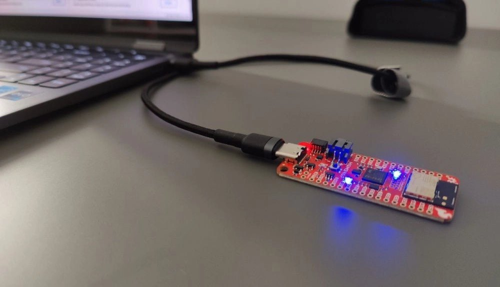
SparkFun Thing Plus Matter (MGM240P): A Versatile Matter-Based IoT Development Board (Review)
The SparkFun Thing Plus Matter (MGM240P) is a versatile and feature-rich development board designed for creating Matter-based IoT devices. Matter, formerly known as Project CHIP...
,
by Lobna Belarbi
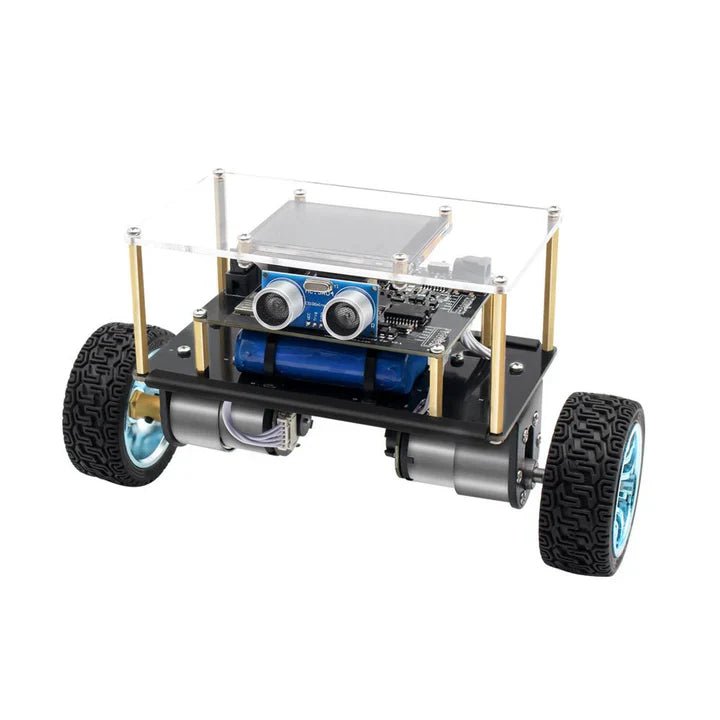
Affordable Robot Kits to Kickstart Your Robotics Journey
Robotics is an exciting and rewarding field, but getting started can be intimidating—especially when it comes to choosing the right kit. Fortunately, Elektor offers a...