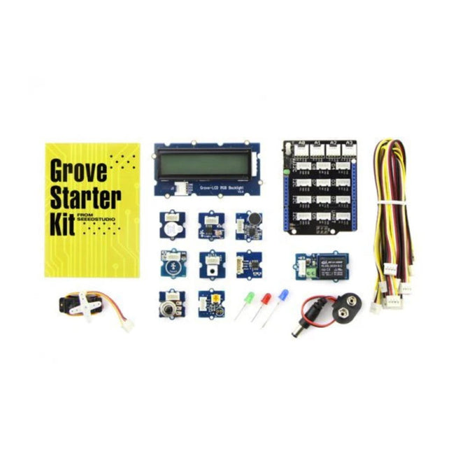
Grove is a modular electronic platform for quick prototyping. Every module has one function, such as touch sensing, creating audio effect and so on. Just plug the modules you need to the base shield, then you are ready to test your idea buds.
This Grove Starter Kit for Arduino is upgraded version of our Grove Starter Kit plus. Frequently used modules have been included in this kit to help you create your concept.
The changes
Optimize the internal slot structure, using technology to make our products inside plastic boxes more regularized, more protective.
Upgrade Instructions for creative poster form, more streamlined and intuitive description for each Grove-Sensor.
Grove-LED increased from three separate PCBA into a. But will still provide three different colors of LED light bulbs for you.
To consider the overall playability of the product experience, we optimized the two Grove-Sensors. Grove-Sound Sensor upgrade to V1.2; Grove-Temperature Sensor upgrade to the new SMD V1.1.
Data line upgrade from 24AWG Grove Cable is 26 AWG Grove Cable, wire length is adjusted to the length of 200mm unified model, the number was adjusted to 10.
Screen perfect upgrade for the Grove-LCD RGB Backlight, color screen makes further enhanced playability experience.
Included
1x Base Shield
1x Grove LCD RGB Backlight
1x Grove Smart Relay
1x Grove Buzzer
1x Grove Sound Sensor
1x Grove Touch Sensor
1x Grove Rotary Angle Sensor
1x Grove Temperature Sensor
1x Grove LED
1x Grove Light Sensor
1x Grove Button
1x DIP LED Blue-Blue
1x DIP LED Green-Green
1x DIP LED Red-Red
1x Mini Servo
10x Grove Cables
1x 9 V to Barrel Jack Adapter
1x Grove starter kit Manual
1x Green Plastic Box
Downloads
Schematic (PDF)
Schematic (Eagle)
Grove Button Source File
Grove LED Source File
Grove Buzzer Source File
Grove Rotary Angle Sensor Source File
Grove Relay Source File
Base Shield Source File
Grove Sound Sensor Source File
Grove Buzzer Source File
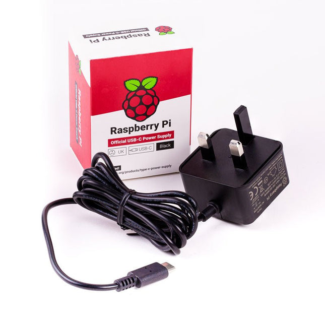
The Raspberry Pi USB-C power supply is designed specifically to power the latest Raspberry Pi 4 Model B computers.
The power supply features a USB-C cable and is available in four different models to suit different international power sockets, and in two colors.
Specifications
Output
Output voltage
+5.1 V DC
Minimum load current
0 A
Nominal load current
3.0 A
Maximum power
15.3 W
Load regulation
±5 %
Line regulation
±2 %
Ripple & noise
120 mVp-p
Rise time
100 ms maximum to regulation limits for DC outputs
Turn-on delay
3000 ms maximum at nominal input AC voltage and full load
Protection
Short circuit protectionOvercurrent protectionOver temperature protection
Efficiency
81% minimum (output current from 100%, 75%, 50%, 25%)72% minimum at 10% load
Output cable
1.5 m 18AWG
Output connector
USB Type-C
Input
Voltage range
100-240 VAC (rated)96-264 VAC (operating)
Frequency
50/60 Hz ±3 Hz
Current
0.5 A maximum
Power consumption (no load)
0.075 W maximum
Inrush current
No damage shall occur, and the input fuse shall not blow
Operating ambient temperature
0-40°C
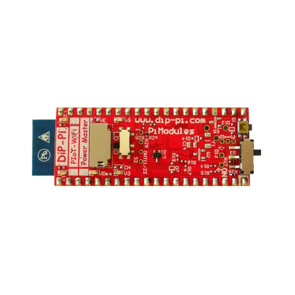
The DiP-Pi WiFi Master is an Advanced WiFi connectivity System with sensors embedded interfaces that cover most of possible needs for IoT application based on Raspberry Pi Pico. It is powered directly from the Raspberry Pi Pico VBUS. The DiP-Pi WiFi Master contains Raspberry Pi Pico embedded RESET button as also ON/OFF Slide Switch that is acting on Raspberry Pi Pico Power Sources.
The DiP-Pi WiFi Master is equipped with WiFi ESP8266 Clone module with embedded antenna. This feature open a wide range of IoT applications based on it.
In Addition to all above features DiP-Pi WiFi Master is equipped with embedded 1-wire, DHT11/22 sensors, and micro–SD Card interfaces. Combination of the extended powering, battery, and sensors interfaces make the DiP-Pi WiFi Master ideal for IoT applications like data logger, plants monitoring, refrigerators monitoring etc.
DiP-Pi WiFi Master is supported with plenty of ready to use examples written in Micro Python or C/C++.
Specifications
General
Dimensions 21 x 51 mm
Raspberry Pi Pico pinout compatible
Independent Informative LEDs (VBUS, VSYS, V3V3)
Raspberry Pi Pico RESET Button
ON/OFF Slide Switch acting on Raspberry Pi Pico Powering Source
Embedded 3.3 V @ 600 mA LDO
ESP8266 Clone WiFi Connectivity
ESP8266 Firmware Upload Switch
Embedded 1-wire Interface
Embedded DHT-11/22 Interface
Powering Options
Raspberry Pi Pico micro-USB (via VBUS)
Embedded Peripherals and Interfaces
Embedded 1-wire interface
Embedded DHT-11/22 Interface
Micro SD Card Socket
Programmer Interface
Standard Raspberry Pi Pico C/C++
Standard Raspberry Pi Pico Micro Python
Case Compatibility
DiP-Pi Plexi-Cut Case
Informative LEDs
VB (VUSB)
VS (VSYS)
V3 (V3V3)
System Protection
Direct Raspberry Pi Pico Hardware Reset Button
PPTC 500 mA @ 18 V fuse on EPR
EPR/LDO Over Temperature protection
EPR/LDO Over Current protection
System Design
Designed and Simulated with PDA Analyzer with one of the most advanced CAD/CAM Tools – Altium Designer
Industrial Originated
PCB Construction
2 ozcopper PCB manufactured for proper high current supply and cooling
6 mils track/6 mils gap technology 2 layers PCB
PCB Surface Finishing – Immersion Gold
Multi-layer Copper Thermal Pipes for increased System Thermal Response and better passive cooling
Downloads
Datasheet
Manual
Pico Breakout Garden Base sits underneath your Pico and lets you connect up to six of our extensive selection of Pimoroni breakouts to it. Whether it's environmental sensors so you can keep track of the temperature and humidity in your office, a whole host of little screens for important notifications and readouts, and, of course, LEDs. Scroll down for a list of breakouts that are currently compatible with our C++/MicroPython libraries!As well as a labelled landing area for your Pico, there's also a full set of broken out Pico connections, in case you need to attach even more sensors, wires, and circuitry. We've thrown in some rubber feet to keep the base nice and stable and to stop it from scratching your desk, or there are M2.5 mounting holes at the corners so that you can bolt it onto a solid surface if you prefer.The six sturdy black slots are edge connectors that connect the breakouts to the pins on your Pico. There's two slots for SPI breakouts, and four slots for I²C breakouts. Because I²C is a bus, you can use multiple I²C devices at the same time, providing they don't have the same I²C address (we've made sure that all of our breakouts have different addresses, and we print them on the back of the breakouts so they're easy to find).As well as being a handy way to add functionality to your Pico, Breakout Garden is also very useful for prototyping projects without the need for complicated wiring, soldering, or breadboards, and you can grow or change up your setup at any time.Features
Six sturdy edge-connector slots for breakouts
4x I²C slots (5 pins)
2x SPI slot (7 pins)
Landing area with female headers for Raspberry Pi Pico
0.1” pitch, 5 or 7 pin connectors
Broken-out pins
Reverse polarity protection (built into breakouts)
99% assembled – just need to stick on the feet!
Compatible with Raspberry Pi Pico
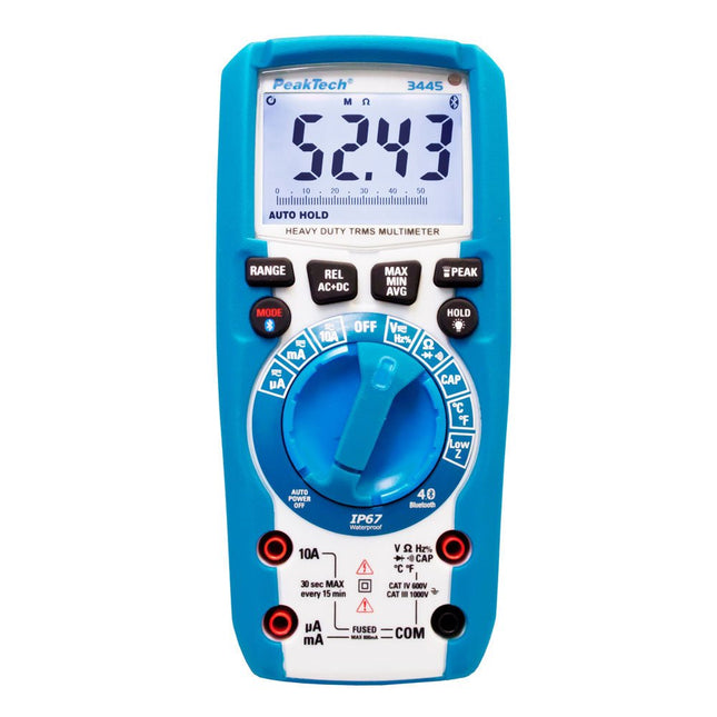
The PeakTech 3445 is a new developed digital multimeter for heavy duty use with a high variety of useful measurement functions.
As unique function, this device has illuminated function buttons and rotary switch, so you can use this IP67 waterproof device even under worst conditions and in total darkness.
In addition to the comprehensive measurement functions for current, voltage, capacity, resistance and many more, this device has a Temperature measutment function, MAX/MIN, Peak and Data-Hold, among many other things.
Through these many technical qualities, this device is suitable for the outdoor use of every electrician, technician and engineer in the service, construction or industrial sector.
Features
Automatic illuminated functions keys and rotary switch
Integrated powerful LED Flashlight
Bleutooth 4.0 interface for data transfer to Android or iOS smartphones
TrueRMS measurement
ACV, ACV+DCV, DCV measurement and Low Impedance (Lo Z)
3 5/6-digits measurement value display (max. 5999)
LCD-Display with Relative-value measurement and 42-segment bargraph
Continuity with buzzer and diode-test
Data-Hold, Min, Max, Peak function and Duty Cycle (Hz / %)
Heavy Duty Case, IP67 dust- and waterproof
Safety: EN 61010-1; CAT III 1000 V / CAT IV 600 V
Accessories: Carrying case, Test Leads, K-type
Specifications
DCV
600 mV / 6 / 60 / 600 / 1000 V +/-0,8% + 5 dgt.
ACV + DCV @ 10 MΩ
6 / 60 / 600 / 1000 V +/-1,5% + 20 dgt.
ACV + DCV @ 3 kΩ (LO Z)
6 / 60 / 600 / 1000 V +/-3% + 30 dgt.
ACV + DCV Frequency range
50 Hz … 400 Hz
ACV
6 / 60 / 600 / 1000 V +/-1% + 5 dgt.
ACV Frequency range
50 Hz … 1000 Hz
DCA
600 / 6000 µA / 60 / 600 mA / 10 A +/-1% + 3 dgt.
ACA
600 / 6000 µA / 60 / 600 mA / 10 A +/-1% + 3 dgt.
ACA Frequency range
50 Hz … 400 Hz
Ohm
600 Ω / 6 / 60 / 600 kΩ / 6 / 60 MΩ +/- 1,5% + 5 dgt.
Capacitance
60 / 600 nF / 6 / 60 / 600 / 6000 µF +/-3% + 5 dgt.
Frequency
10 Hz … 10 kHz +/- 1,0% + 5 dgt.
Temperature
20.0 °C … +760 °C +/-1,0% + 5 °C
Interface
Bluetooth 4.0 Low Energy
Operating Voltage
4 x 1,5 V AAA Batteries
Dimensions (WxHxD)
75 x 170 x 50 mm
Weight
400 g
The Challenger RP2040 NFC is a small embedded computer, equipped with an advanced on-board NFC controller (NXP PN7150), in the popular Adafruit Feather form factor. It is based on an RP2040 microcontroller chip from the Raspberry Pi Foundation which is a dual-core Cortex-M0 that can run on a clock up to 133 MHz.
NFC
The PN7150 is a full featured NFC controller solution with integrated firmware and NCI interface designed for contactless communication at 13.56 MHz. It is fully compatible with NFC forum requirements and is greatly designed based on learnings from previous NXP NFC device generation. It is the ideal solution for rapidly integrating NFC technology in any application, especially small embedded systems reducing Bill of Material (BOM).
The integrated design with full NFC forum compliancy gives the user all the following features:
Embedded NFC firmware providing all NFC protocols as pre-integrated feature.
Direct connection to the main host or microcontroller, by I²C-bus physical and NCI protocol.
Ultra-low power consumption in polling loop mode.
Highly efficient integrated power management unit (PMU) allowing direct supply from a battery.
Specifications
Microcontroller
RP2040 from Raspberry Pi (133 MHz dual-core Cortex-M0)
SPI
One SPI channels configured
I²C
Two I²C channel configured (dedicated I²C for the PN7150)
UART
One UART channel configured
Analog inputs
4 analog input channels
NFC module
PN7150 from NXP
Flash memory
8 MB, 133 MHz
SRAM memory
264 KB (divided into 6 banks)
USB 2.0 controller
Up to 12 MBit/s full speed (integrated USB 1.1 PHY)
JST Battery connector
2.0 mm pitch
On board LiPo charger
450 mA standard charge current
Dimensions
51 x 23 x 3,2 mm
Weight
9 g
Note: Antenna is not included.
Downloads
Datasheet
Quick start example
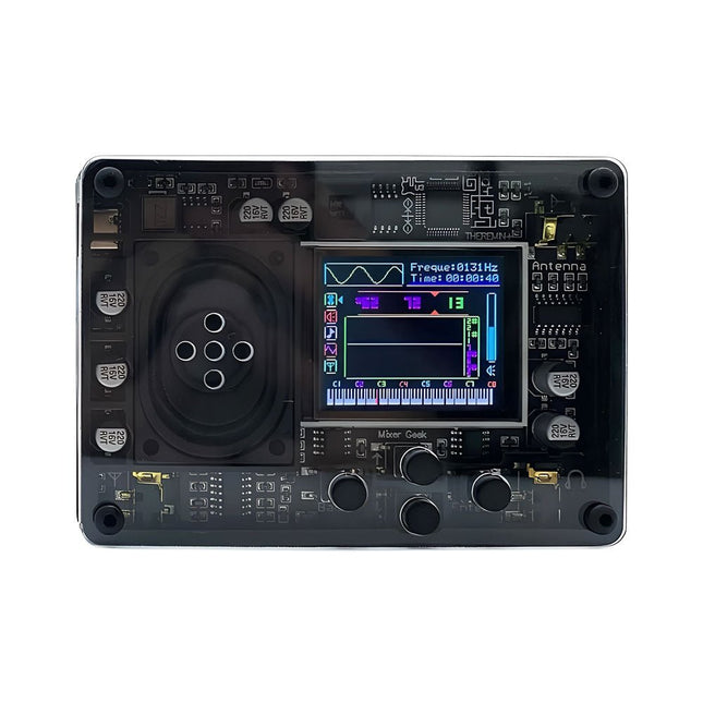
The Mixer Geek Theremin+ is a fun and innovative electronic musical instrument inspired by the classic Theremin. Unlike traditional instruments, the Theremin+ is played without physical contact, using hand movements in the air to control pitch and volume.
The Theremin+ offers an exciting and hands-on way to explore music and sound experimentation.
Features
Ready to use out of the box
Equipped with a loudspeaker and full-color screen
Intuitive button-based navigation and confirmation
Choose from over 70 tones
Multiple customizable function settings
Displays waveform, time, frequency, volume, and corresponding piano pitch (display can be turned off)
Powered via USB-C port; compatible with power banks
Compact design with removable telescopic antenna for easy storage
Connects to headphones, external speakers, or recording devices
Dimensions: 98 x 70 x 18 mm
Included
1x Theremin+ Musical Instrument
2x Antennas
1x USB-C cable
The JLINK V9 USB-JTAG Arm Emulator/Debugger is a high-performance and reliable tool for programming and debugging ARM Cortex-M, Cortex-A/R, and other supported microcontrollers via JTAG and SWD interfaces.
Features
Universal Compatibility: Supports a wide range of ARM-based MCUs and cores including Cortex-M0, M3, M4, M7, A5, A7, A9, and R4.
High-Speed Performance: Fast data throughput for both flash programming and real-time debugging with minimal latency.
Multi-Interface Support: Offers both JTAG and SWD modes, enabling flexible use in different development environments.
Plug & Play via USB: Easy connection to your PC with USB 2.0 interface; no external power supply required.
Robust Software Support: Fully compatible with SEGGER J-Link software tools and supported by major IDEs including Keil MDK, IAR EWARM, SEGGER Embedded Studio, and others.
Included
1x JLINK V9 USB-JTAG Arm Emulator/Debugger
1x USB Cable
1x Connector Cable
The board's main processor is a low-power ARM Cortex-M0 32-bit SAMD21, like in the other boards within the Arduino MKR family. The WiFi and Bluetooth connectivity is performed with a module from u-blox, the NINA-W10, a low-power chipset operating in the 2.4 GHz range. On top of that, secure communication is ensured through the Microchip ECC508 crypto chip. Besides that, you can find a battery charger, and an RGB LED on-board.
Official Arduino WiFi Library
You can get your board to connect to any kind of existing WiFi network, or use it to create your own Arduino Access Point. The specific set of examples we provide for the MKR WiFi 1010 can be consulted at the WiFiNINA library reference page.
Compatible with other Cloud Services
It is also possible to connect your board to different Cloud services, Arduino's own among others. Here are some examples of how to get the MKR WiFi 1010 to connect to:
Blynk: a simple project from the Arduino community connecting to Blynk to operate your board from a phone with little code
IFTTT: in-depth case of building a smart plug connected to IFTTT
AWS IoT Core: Arduino made this example on how to connect to Amazon Web Services
Azure: visit this GitHub repository explaining how to connect a temperature sensor to Azure's Cloud
Firebase: you want to connect to Google's Firebase, this Arduino library will show you how
Specifications
Microcontroller
SAMD21 Cortex-M0+ 32bit low power ARM MCU
Radio Module
u-blox NINA-W102
Power Supply
5 V
Secure Element
ATECC508
Supported Battery
Li-Po Single Cell, 3.7 V, 1024 mAh Minimum
Operating Voltage
3.3 V
Digital I/O Pins
8
PWM Pins
13
UART
1
SPI
1
I2C
1
Analog Input Pins
7
Analog Output Pins
1
External Interrupts
10
Flash Memory
256 KB
SRAM
32 KB
EEPROM
no
Clock Speed
32.768 kHz, 48 MHz
LED_Builtin
6
USB
Full-Speed USB Device and embedded Host
Length
61.5 mm
Width
25 mm
Weight
32 g
Elektor GREEN and GOLD members can download their digital edition here.
Not a member yet? Click here.
USB Measurement AdapterTesting Current and Signal Quality of USB Ports
4...20 mA Current Output for Arduino UnoA Reliable, EMI-Insensitive Current Loop Interface
Vacuum Cleaner Automatic ControlKeep Your Tools’ Work Area Clean
DDS Generator with ATtiny
Opamp-Tester V2New PCB – Now Also Suitable for SMDs
550-mW “Lamp” Audio AmplifierGet the Warm Sound of Vacuum Tubes With Ease
Fuse GuardMonitoring a Fuse with a Flashing LED
HQ RIAA PreamplifierGet the Most Out of Your Vinyl Records!
Turntable Speed CalibratorAn Arduino-Based 100–120 Hz Strobe Light Generator
Elektor Classics: video buffer/repeater
Infrared Remote-Controlled DimmerControl Your Halogen or LED Floor Lamp Effortlessly and With Style
How to Use switch…case on Strings in C++/Arduino IDE
Magnet FinderWith a Simple Hall-Effect Sensor
Raspberry Pi Smart Power ButtonA Solution for Raspberry Pi Up to Model 4
Essential Maker TipsProfessional Insights for Everyday Making
Practical Projects with the 555 TimerDC Motor Control and Fast Reaction Challenges
Basic AC-Load-On MonitorSave Energy with a Simple Device
Power Banks in ParallelA Three-Day Continuous Power Solution
VFO Up to 15 MHzAn Implementation With Raspberry Pi Pico
Violin Tuner with ATtiny202
Elektor Classics: video amplifier for B/W television sets
Capacitance Meter20 pF to 600 nF
Quasi-Analog Clockwork Mk IITwo LED Rings for Hours and Minutes
You Can Do Anything You Want(with the Arduino Ecosystem at Your Side)
Neon Lamp Dice
Elektor Classics: RTTY calibrator indicator
Inspiring Hardware Designs for Your ESPs
Elektor Classics: variable 3 A power supply
RGB LEDs with Integrated Control CircuitLight with Precision: ICLEDs Set Standards
Experiment: Towards a Mixed-Signal Theremin?Blending Modern Time-of-Flight Sensors With the Timeless XR2206 Analog Generator
ESP32 Audio Transceiver Board (Part 1)SD Card WAV File Player Demo
Infographics: Circuits and Circuit Design 2025
Small Audio MixerA Simple and Versatile Scalable Design
Smart Staircase Light TimerSave More Money on the Energy Bill!
Smarten Up Your ShuttersControlling Velux Hardware With an ESP32 and MQTT
Solid-State Foot WarmerEnergy-Efficient Comfort
Is the M5Stamp Fly Quadcopter the Next Tello?
Boosting Wi-Fi Range of the ESP32-C3 SuperMiniA Simple and Effective Antenna Mod
ZD-8968 Hot-Air Soldering StationA Budget-Friendly Workhorse or Just Hot Air?
Parking Sensor TesterFinding Defects in the PDC System of a Car
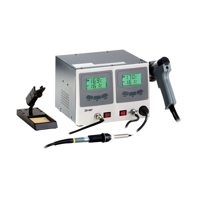
The ZD-987 Soldering & Desoldering Station is a high-performance, multifunctional tool designed for electronic product research, manufacturing, and rework. It is ideal for use in laboratories, education, and production environments – especially for repairing and reworking electronic devices and communication equipment.
The soldering iron and desoldering gun are each controlled automatically by dedicated microprocessors. Thanks to digital control electronics, a high-precision sensor, and an efficient heat exchange system, the station ensures accurate temperature regulation at the soldering tip.
Maximum temperature accuracy and optimal thermal response under load are achieved through rapid, precise measurement within a closed-loop control circuit. This design is specifically optimized for lead-free soldering processes.
Soldering Iron
The 60 W soldering iron, compatible with a wide range of N4 series soldering tips, is suitable for virtually any task in the electronics field. Its high power output and slim design make it ideal for precise, fine-pitch soldering work.
Equipped with a PTC heating element and a sensor located directly at the soldering tip, the iron ensures fast and accurate temperature control for consistent soldering results.
Desoldering Gun
The 80 W desoldering gun, compatible with a wide range of N5 series tips, is suitable for virtually any desoldering task in the electronics field. Its high power output and ergonomic gun-type design make it perfect for precise and detailed desoldering work.
Featuring a PTC heating element and a sensor located directly at the desoldering tip, it ensures rapid and accurate temperature control for consistent performance.
Features
Ideal for production and service use
The soldering iron and desoldering gun can be operated independently or simultaneously
Dual two-line LCD readout simultaneously displays tip temperature and setpoint in °C or °F
Adjustable temperature range from 160°C to 480°C (320°F to 896°F)
Push-button up/down control for temperature setting
Specifications
Voltage
220-240 V, 50 Hz
Power
160 W
Included
1x ZD-987 Soldering & Desoldering Station (Unit)
1x Soldering iron
1x Desoldering gun
1x Soldering iron stand with sponge
1x Desoldering iron stand
4x Filters
2x Nozzles
3x Clearing tool set
1x Black air nozzle with seal ring
1x Cable
1x Manual
The DSO154Pro with advanced ARM+FPGA architecture is a portable oscilloscope with a bandwidth of 18 MHz and a sampling rate of 40 MSa/s.
It has an integrated signal generator that can output adjustable waveforms with an amplitude of 3 V and a frequency range of 0-500 KHz.
Features
18 MHz bandwidth
40 MSa/s sampling rate
500 KHz signal generator
2.4" display
14 measurement parameters
Auto adjustment
Probe support: X1, X10, X100
Auto shutdown
Specifications
Bandwidth
18 MHz
Sampling rate
40 MSa/s
Display
2.4" color TFT (320 x 240)
Measurements
14 types
Vertical precision
±2%
Rise time
<3ns
Storage depth
16 Kb
Impedance
1 MΩ
Time base
50ns-10s
Vertical sensitivity
20 mV/div-10 V/div
Max voltage
±40 V (x1)±400 V (x10)
Trigger mode
Auto/Normal/Single
Trigger type
Rise/Fall
Trigger level
Manual/Auto
Display mode
YT/Roll
Persistence
None/1s/∞
Waveforms
Sinus/Square/Triangle/Noise
Frequency
0-500 KHz
Power supply
USB-C (5 V)
Battery
1000 mAh Lithium battery
Dimensions
87 x 58 x 18 mm
Weight
80 g
Included
1x DSO154Pro Oscilloscope
1x P6100 probe
1x USB cable
1x Ring-shaped bracket
1x Manual
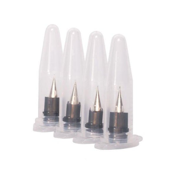
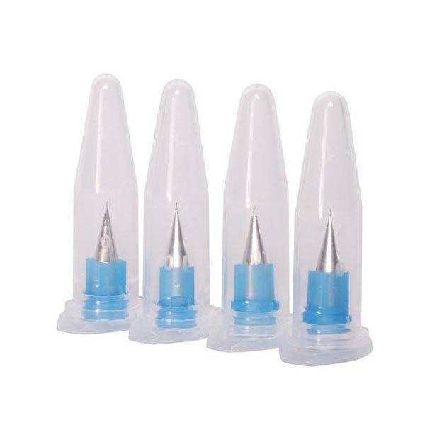
Keep printing with a pack of 4 nozzles (225 micron inner diameter). These metal dispensing tips offer excellent resolution and accurate deposition of ink and solder paste.
If you want to push the resolution limits of the V-One, these dispensing tips will help enable your experimental projects. This pack contains 4 extra fine nozzles with an internal diameter of 0.150 mm (6 mil).
Do not use with solder paste! It will clog!
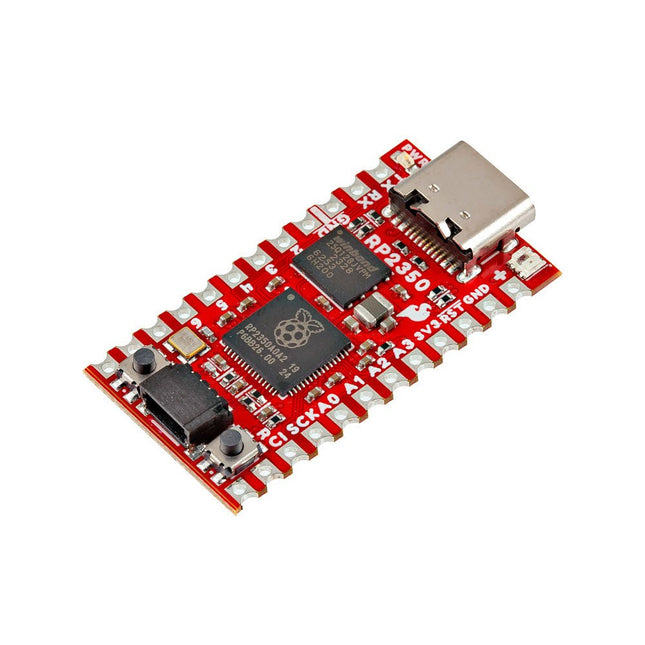
The SparkFun RP2350 Pro Micro provides a powerful development platform, built around the RP2350 microcontroller. This board uses the updated Pro Micro form factor. It includes a USB-C connector, Qwiic connector, WS2812B addressable RGB LED, Boot and Reset buttons, resettable PTC fuse, and PTH and castellated solder pads.
The RP2350 is a unique dual-core microcontroller with two ARM Cortex-M33 processors and two Hazard3 RISC-V processors, all running at up to 150 MHz! Now, this doesn't mean the RP2350 is a quad-core microcontroller. Instead, users can select which two processors to run on boot instead. You can run two processors of the same type or one of each. The RP2350 also features 520 kB SRAM in ten banks, a host of peripherals including two UARTs, two SPI and two I²C controllers, and a USB 1.1 controller for host and device support.
The Pro Micro also includes two expanded memory options: 16 MB of external Flash and 8 MB PSRAM connected to the RP2350's QSPI controller. The RP2350 Pro Micro works with C/C++ using the Pico SDK, MicroPython, and Arduino development environments.
Features
RP2350 Microcontroller
8 MB PSRAM
16 MB Flash
Supply Voltage
USB: 5 V
RAW: 5.3 V (max.)
Pro Micro Pinout
2x UART
1x SPI
10x GPIO (4 used for UART1 and UART0)
4x Analog
USB-C Connector
USB 1.1 Host/Device Support
Qwiic Connector
Buttons
Reset
Boot
LEDs
WS2812 Addressable RGB LED
Red Power LED
Dimensions: 33 x 17.8 mm
Downloads
Schematic
Eagle Files
Board Dimensions
Hookup Guide
RP2350 MicroPython Firmware (Beta 04)
SparkFun Pico SDK Library
Arduino Pico Arduino Core
Datasheet (RP2350)
Datasheet (APS6404L PSRAM)
RP2350 Product Brief
Raspberry Pi RP2350 Microcontroller Documentation
Qwiic Info Page
GitHub Repository
The SparkFun MicroMod mikroBUS Carrier Board takes advantage of the MicroMod, Qwiic, and mikroBUS ecosystems making it easy to rapidly prototype with each of them, combined. The MicroMod M.2 socket and mikroBUS 8-pin header provide users the freedom to experiment with any Processor Board in the MicroMod ecosystem and any Click board in the mikroBUS ecosystem, respectively. This board also features two Qwiic connectors to seamlessly integrate hundreds of Qwiic sensors and accessories into your project. The mikroBUS socket comprises a pair of 8-pin female headers with a standardized pin configuration. The pins consist of three groups of communications pins (SPI, UART and I²C), six additional pins (PWM, Interrupt, Analog input, Reset and Chip select), and two power groups (3.3 V and 5 V). While a modern USB-C connector makes programming easy, the Carrier Board is also equipped with a MCP73831 Single-Cell Lithium-Ion/Lithium-Polymer Charge IC so you can charge an attached single-cell LiPo battery. The charge IC receives power from the USB connection and can source up to 450 mA to charge an attached battery. Features M.2 MicroMod (Processor Board) Connector USB-C Connector 3.3 V 1 A Voltage Regulator 2x Qwiic Connectors mikroBUS Socket Boot/Reset Buttons Charge Circuit JTAG/SWD PTH Pins Downloads Schematic Eagle Files Board Dimensions Hookup Guide Getting Started with Necto Studio mikroBUS Standard Qwiic Info Page GitHub Hardware Repo
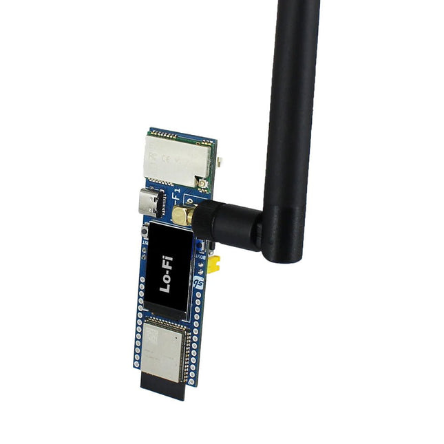
Lo-Fi (ESP32 + LoRa combination) is the perfect solution for anyone looking to establish long-range wireless communication in a variety of applications with WiFi capabilities. LoRa offers exceptional range and easy connectivity, it allows you to seamlessly communicate with devices up to 5 km away.
Devices provide an efficient and trustworthy choice for long-range wireless communication in addition to WiFi access to link internet clouds best suited for Internet of Things applications, enabling connectivity in remote and challenging settings.
Features
Device powered by powerful ESP32 S3 WROOM-1 which is having Xtensa dual-core 32-bit LX7 microprocessor, up to 240 MHz
Inbuilt Wi-Fi & Bluetooth LE for wireless connectivity
Type C interface for Programming/Power
1.14" TFT display for visual interactions
GPIO breakouts for interfacing additional peripherals
Breadboard compatible for easy DIY breadboarding projects
2 separate user programmable buttons along with Reset and Boot buttons
3.7 V Lithium Battery connector for a portable use case with an onboard charging option
Use new generation LoRa spread spectrum to ensure stable communication
For LoRa, faster speed and a longer data transmission range of up to 5 km
Applications
Internet of Things (IoT)
Smart Home Automation
Agricultural Automation
Emergency Services
Environmental Monitoring
Industrial Automation
Specifications
Microcontroller: ESP32 S3 WROOM-1
Wireless Interface: WiFi, BLE, LoRa
Protocol: 802.11b/g/n, Bluetooth 5.0
Memory Size: 16 MB Flash, 384 kB ROM, 8 MB SRAM
Supply Voltage: 5 V
Operating Voltage: 3.3 V
Display Size: 1.14”
Display Type: TFT
Display resolution: 135 x 240 pixels
Display driver: ST7789V
Display Appearance: RGB
Display color: 4k/65k/252k
Display Luminance: 400 Cd/m²
Operating Temperature: -20 to 70°C
Storage Temperature: -30 to 80°C
LoRa Module Specs:
Carrier Frequency (License Free ISM): 868 MHz
Chip: Based on SX1262 RF chip
Range: 5Km
Transmitting Power: 22 dBm
Receiving Sensitivity: -147 dbm
Data Rate: Up to 62.5 kbps
Communication Port: UART serial
Downloads
Getting started guide
Hardware design files
Included
1x Lo-Fi Board
1x Antenna (868 MHz)
ArdiPi is the ultimate Arduino Uno alternative packed with powerful specs and exciting features in the Arduino Uno form factor. You can enjoy a low-cost solution with access to the largest support communities for Raspberry Pi.
ArdiPi variant is powered by Raspberry Pi Pico W. The built-in Wi-Fi and Bluetooth connectivity makes the board ideal for IoT projects or projects requiring wireless communication.
Features
Arduino Uno form factor, so you can connect 3.3 V compatible Arduino shields
SD card slot for storage and data transfer
Drag-and-drop programming using mass storage over USB
Multifunction GPIO breakout supporting general I/O, UART, I²C, SPI, ADC & PWM functions.
Multi-tune Buzzer to add audio alert into the project
SWD pins breakout for serial debugging
Multi-platform support like Arduino IDE, MicroPython, and CircuitPython.
Comes with HID support, so the device can simulate a mouse or keyboard
Specifications
Powered by RP2040 microcontroller which is a dual-core Arm Cortex-M0+ processor, 2 MB of onboard flash storage, 264 kB of RAM
On-board single-band 2.4 GHz wireless interfaces (802.11n) for WiFi and Bluetooth 5 (LE)
WPA3 & Soft access point supporting up to four clients
Operating voltage of pins 3.3 V and board supply 5 V
25 Multipurpose GPIOs breakout in Arduino style for easy peripheral interfacing
I²C, SPI, and UART communications protocol support
2 MB of onboard Flash memory
Cross-platform development and multiple programming language support
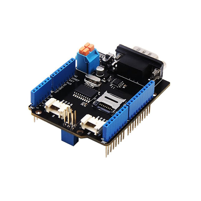
Features Implements CAN V2.0B at up to 1 Mb/s Industrial standard 9 pin sub-D connector OBD-II and CAN standard pinout selectable. Changeable chip select pin Changeable CS pin for TF card slot Changeable INT pin Screw terminal that easily to connect CAN_H and CAN_L Arduino Uno pin headers Micro SD card holder 2 Grove connectors (I2C and UART) SPI Interface up to 10 MHz Standard (11 bit) and extended (29 bit) data and remote frames Two receive buffers with prioritized message storage
Features Integrated Cold-Junction Compensation Supported Types (designated by NIST ITS-90): Type K, J, T, N, S, E, B and R Four Programmable Temperature Alert Outputs: Monitor Hot- or Cold-Junction Temperatures Detect rising or falling temperatures Up to 255°C of Programmable Hysteresis Programmable Digital Filter for Temperature Low Power Dimensions: 20 mm x 40 mm x 18 mm Weight: 18 g Application Petrochemical Thermal Management Hand-Held Measurement Equipment Industrial Equipment Thermal Management Ovens Industrial Engine Thermal Monitor Temperature Detection Racks Downloads Eagle Files Github library Datasheet
This Grove - PIR Motion Sensor(Passive Infrared Sensor) can detect infrared signals caused by motion. If the PIR sensor notices the infrared energy, the motion detector is triggered and the sensor outputs HIGH on its SIG pin. The detecting range and response speed can be adjusted by 2 potentiometers soldered on its circuit board, The response speed is from 0.3s - 25s, and max 6 meters of detecting range. The Grove - PIR Motion Sensor(Passive Infrared Sensor) is an easy-to-use motion sensor with Grove compatible interface. Simply connecting it to Base Shield and programming it, it can be used as a suitable motion detector for Arduino projects. For example, the PIR Motion Sensor is commonly used in security alarm systems and automatic lighting applications. Features Grove compatible interface Voltage range: 3 V – 5 V Size: 20 mm x 40 mm Detecting angle: 120 degree Detecting Max distance: 6m (3m by default) Adjustable detecting distance and holding time Applications Motion Sensor Motion Detector Security Alarm System Human Detection System Technical Specifications Dimensions 40 mm x 20 mm x 15 mm Weight 12 g Battery Exclude Voltage range 3 V – 5 V Detecting angle 120 degree Detecting distance max 6m (3m by default)
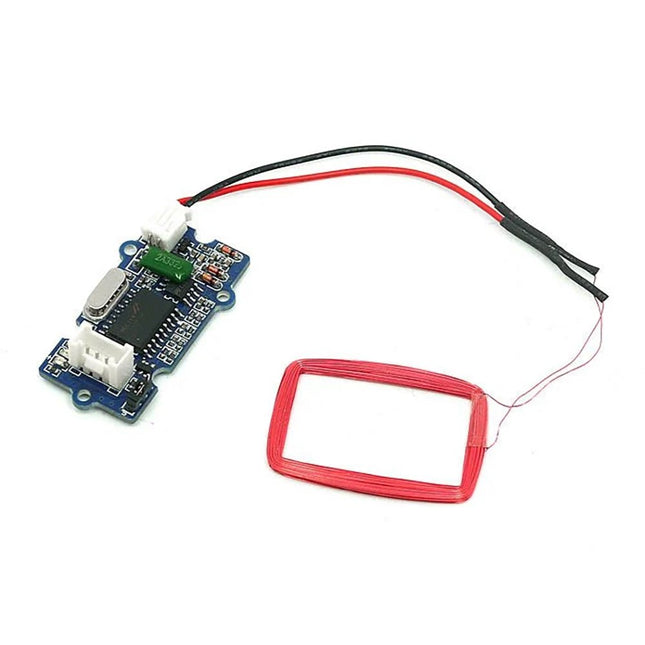
Features Selectable output format: Uart or Wiegand. 4Pins Electronic Brick Interface High Sensitivity Specifications Dimensions: 44 mm x 24 mm x9.6 mm Weight: 15 g Battery: Exclude Voltage: 4.75 V - 5.25 V Working Frequency: 125 kHz Sensing Distance(Max): 70 mm TTL Output: 9600 baud rate, 8 data bits, 1 stop bit, and no verify bit Wiegand Output: 26 bits Wiegand format, 1 even verify bit, 24 data bits, and 1 odd verify bit
Inventor 2040 W is a multi-talented board that does (almost) everything you might want a robot, prop or other mechanical thing to do. Drive a couple of fancy motors with encoders attached? Yep! Add up to six servos? Sure? Attach a little speaker so you can make noise? No problem! It's also got a battery connector so you can power your inventions from AA/AAA or LiPo batteries and carry your miniature automaton/animated top hat/treasure chest that growls at your enemies around with you untethered.You also get a ton of options for hooking up sensors and other gubbins – there's two Qw/ST connectors (and an unpopulated Breakout Garden slot) for attaching breakouts, three ADC pins for analog sensors, photoresistors and such, and three spare digital GPIO you could use for LEDs, buttons or digital sensors. Speaking of LEDs, the board features 12 addressable LEDs (AKA Neopixels) – one for each servo and GPIO/ADC channel.Features
Raspberry Pi Pico W Aboard
Dual Arm Cortex M0+ running at up to 133 Mhz with 264 kB of SRAM
2 MB of QSPI flash supporting XiP
Powered and programmable by USB micro-B
2.4 GHz wireless
2 JST-SH connectors (6 pin) for attaching motors
Dual H-Bridge motor driver (DRV8833)
Per motor current limiting (425 mA)
Per motor direction indicator LEDs
2 pin (Picoblade-compatible) connector for attaching speaker
JST-PH (2 pin) connector for attaching battery (input voltage 2.5-5.5 V)
6 sets of header pins for connecting 3 pin hobby servos
6 sets of header pins for GPIO (3 of which are ADC capable)
12x addressable RGB LEDs/Neopixels
User button
Reset button
2x Qw/ST connectors for attaching breakouts
Unpopulated headers for adding a Breakout Garden slot
Fully assembled
No soldering required (unless you want to add the Breakout Garden slot).
C/C++ and MicroPython libraries
Schematic
Downloads
Download pirate-brand MicroPython
Getting Started with Raspberry Pi Pico
Motor function reference
Servo function reference
MicroPython examples
C++ examples