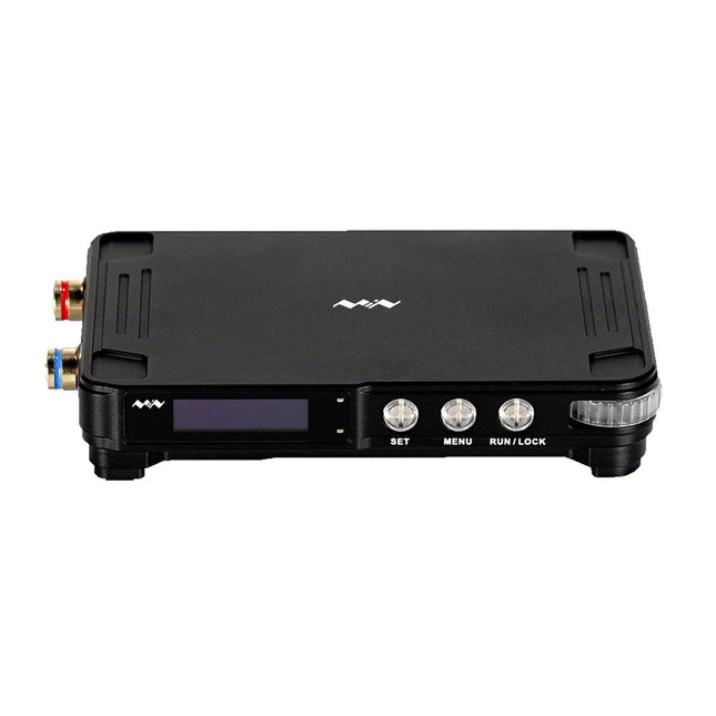
MDP (Mini Digital Power System) is a system of programmable linear DC power supply based on modular design, capable of connecting different modules for use as needed. MDP-XP consists of a display control module (MDP-M01) and a digital power module (MDP-P906).
Through 2.4 GHz wireless connection, it achieves multichannel free combination at the power of 300 W per channel. MDP-XP is a high cost-effective programmable linear DC power supply, featuring indicators, stability, reliability and distinct user interface comparable with professional power supplies; it also provides programmable output, timing output, sequential control, automatic compensation and other powerful functions, so as to meet diversified testing needs.
MDP-M01 Display Control Module: equipped with a 2.8-inch TFT screen, it can display the voltage-current waveform in real time, support data statistics, and automatically pair with and control six sub-modules (digital power modules), with dual thumb wheels and 90-degree scrolling user-friendly design.
MDP-P906 Digital Power Module: high efficiency linear output, 0.25 mV ripple wave, high-speed transient response, and supporting precise fine-tuning.
Specifications (MDP-M01)
Screen size
2.8' TFT
Screen resolution
240 x 320
Power
Micro USB power input, or taking power from sub-module via dedicated power cable
Input
DC 5 V/0.3 A
Other functions
Can control up to 6 sub-modulesUpgrade formware through Micro USB
Dimensions
107 x 66 x 13.6 mm
Weight
133 g
Specifications (MDP-P906)
Input
DC 4.2-30 V/14 A (Max)QC 3.0/PD2.0, 20 V/5 A (Max)
Output
0-30 V/0-10 A, 300 W (Max)
Conversion efficiency
95%
Output resolution
10 mV/2 mA, up to 1 mV/1 mA via Display Control module
Output accuracy
0.03%+5 mV0.05%+2 mV
Adjustment rate
Load adjustment rate <±0.01%Power adjustment rate <±0.01%
Ripple and noise
<250 uVrms, 3 mVpp; 2 mArms
Transient response
<4 uS
Safety protections
Input over-voltage, under-voltage, reverse connection protection, output over-current, back-flow protection and over-temperature protection
Others
Automatically shut-down and enter micro-power modeSupport USB firmware upgrade
Dimensions
112 x 66 x 20 mm
Weight
181 g
Included
MDP-M01
1x MDP-M01 Smart Digital Monitor
1x Cable (2.5 mm jack to Micro USB)
MDP-P906
1x MDP-P906 Digital Power Supply
2x Output Cable
1x User Manual
Downloads
MDP-M01 User Manual v3.4
MDP-P906 User Manual v1.1
Firmware v1.32
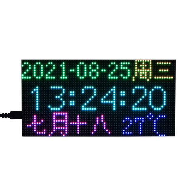
This is a RGB LED matrix digital clock designed for Raspberry Pi Pico. It incorporates high precision RTC chip DS3231, photosensor, buzzer, IR receiver, and buttons, features multiple functions including accurate electronic clock, temperature display, auto brightness adjustment, alarm, and button config. The important part is, rich open source codes and development tutorials are also provided to help you fast get started with Raspberry Pi Pico and make your own original electronic clock. Features Standard Raspberry Pi Pico header, supports Raspberry Pi Pico series Using P3 fine-pitch RGB LED matrix panel, with 2048 individual RGB LEDs, 64×32 pixels, 3 mm pitch, allows displaying text, colorful image, or animation Onboard high precision RTC chip DS3231, with backup battery holder (battery included), maintains accurate timekeeping when main power is off Real-Time Clock Counts Seconds, Minutes, Hours, Date of the Month, Month, Day of the Week, and Year with Leap-Year Compensation Valid Up to 2100 Optional format: 24-hour OR 12-hour with an AM/PM indicator 2x programable alarm clock Digital temperature sensor output: ±3°C accuracy Embedded photosensor for auto brightness adjustment due to the ambient light, power saving and eye care Embedded buzzer for alarm or hourly ring, etc. IR receiver, combined with the IR remote controller, supports IR wireless control 5x buttons for configuration, reset, and code programming Quality acrylic back panel and dimmer panel, better looking, more comfortable displaying Comes with development resources and manual (Raspberry Pi Pico C/C++ and MicroPython examples) Included 1x Pico-RGB-Matrix-P3-64x32 base board 1x RGB-Matrix-P3-64x32 LED matrix and accessories 1x Black acrylic back panel 1x Dark brown acrylic front panel 1x IR remote controller 1x Double-sided tape 1x Screws pack Downloads Documentation
The Data Logging Carrier Board breaks out connections for I²C via a Qwiic connector or standard 0.1'-spaced PTH pins along with SPI and serial UART connections for logging data from peripheral devices using those communication protocols.
The Data Logging Carrier Board allows you to control power to both the Qwiic connector on the board and a dedicated 3.3 V power rail for non-Qwiic peripherals so you can pick and choose when to power the peripherals you are monitoring the data from. It also features a charging circuit for single-cell Lithium-ion batteries along with a separate RTC battery-backup circuit to maintain power to a real-time clock circuit on your Processor Board.
Features
M.2 MicroMod Connector
microSD socket
USB-C Connector
3.3 V 1 A Voltage Regulator
Qwiic Connector
Boot/Reset Buttons
RTC Backup Battery & Charge Circuit
Independent 3.3 V regulators for Qwiic bus and peripheral add-ons
Controlled by digital pins on Processor Board to enable low power sleep modes
Phillips #0 M2.5 x 3 mm screw included
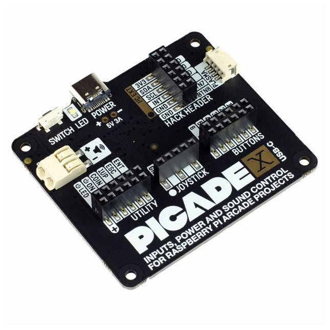
Turn your Raspberry Pi into a retro games console! Picade X HAT includes joystick and button inputs, a 3 W I²S DAC/amplifier, and soft power switch. This HAT has all the same great features as the original Picade HAT but now has no-fuss female Dupont connectors to hook up your joystick and buttons. Simply pop Picade X HAT onto your Pi, plug a USB-C power supply into the connector on the HAT (it back-powers your Pi through the GPIO, so no need for a separate power supply), wire up your controls, and install the driver! It's ideal for your own DIY arcade cabinet builds, or for interfaces that need big, colourful buttons and sound. Features I²S audio DAC with 3 W amplifier (mono) and push-fit terminals Safe power on/off system with tactile power button and LED USB-C connector for power (back-powers your Pi) 4-way digital joystick inputs 6x player button inputs 4x utility button inputs 1x soft power switch input 1x power LED output Plasma button connector Breakout pins for power, I²C, and 2 additional buttons Picade X HAT pinout Compatible with all 40-pin Raspberry Pi models The I²S DAC blends both channels of digital audio from the Raspberry Pi into a single mono output. This is then passed through a 3 W amplifier to power a connected speaker. The board also features a soft power switch that allows you turn your Pi on and off safely without risk of SD card corruption. Tap the connected button to start up, and press and hold it for 3 seconds to fully shutdown and disconnect power. Software/Installation Open a terminal and type curl https://get.pimoroni.com/picadehat | bash to run the installer. You'll need to reboot once the installation is complete, if it doesn't prompt you to do so. The software does not support Raspbian Wheezy Notes With USB-C power connected through Picade X HAT you'll need either to tap the connected power button or the button marked 'switch' on the HAT to power on your Pi.
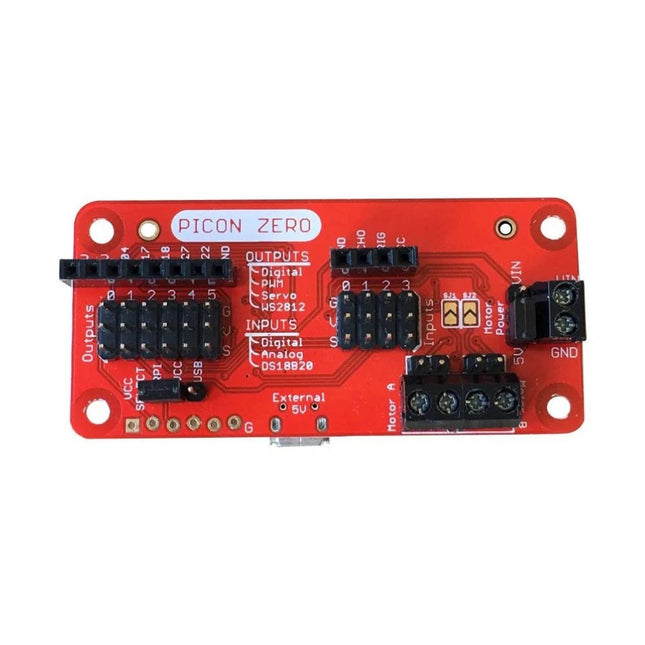
The Picon Zero is an add-on for the Raspberry Pi. It has the same size as a Raspberry Pi Zero, making it ideal to function as a pHat. Of course, it can be used on any other Raspberry Pi via a 40-pin GPIO connector.
As well as two full H-Bridge motor drivers, the Picon Zero has several Input/Output pins giving you multiple configuration options. That allows you to easily add outputs or analog inputs to your Raspberry Pi without any complicated software or kernel-specific drivers. At the same time, it opens up 5 GPIO pins from the Raspberry Pi, and it provides the interface for an HC-SR04 ultrasonic distance sensor.
The Picon Zero comes with all components, including the headers and screw terminals, fully soldered. Soldering isn't required. You can use it right out of the box.
Features
pHat format PCB: 65 mm x 30 mm
Two full H-Bridge motor drivers. Drive up to 1.5 A continuously per channel, at 3 V - 11 V.
Each motor output has both a 2-pin male header and a 2-pin screw terminal.
The motors can be powered from the Picon Zero's 5 V or an external power source (3 V - 11 V).
The Picon Zero's 5 V can be selected to be from the Raspberry Pi's 5 V line, or a USB connector on the Picon Zero. That means that you can effectively have 2 USB battery banks: one to power the servos and motors on the Picon Zero and the other to power the Pi.
4 Inputs that can accept up to 5 V. These inputs can be configured as follows:
Digital inputs
Analog inputs
DS18B20
DHT11
6 Outputs that can drive 5 V and be configured as:
Digital Output
PWM Output
Servo
NeoPixel WS2812
All Inputs and Outputs use GVS 3-pin male headers.
4-pin female header that connects directly to an HC-SR04 ultrasonic distance sensor.
8-pin female header for Ground, 3.3 V, 5 V, and 5 GPIO signals allowing you to add their additional features.
Features Compatible with Raspberry Pi 4 only
Cutout in lid for 40x30mm heatsink or Fan SHIM
Super-slimline profile Fully HAT-compatible Protects your beloved Pi Clear top and base leave Raspberry Pi 4 visible GPIO cut-out Handy laser-etched port labels Leaves all ports accessible Made from lightweight, high-quality, cast acrylic Great for hacking and tinkering! Made in Sheffield, UK Weighing just over 50 grams, the case is lightweight and ideal for mounting to any surface. No tools are required for assembly or disassembly. The dimensions are: 99 × 66 × 15 mm. In the video below you can see a quick assembly guide.
Add colors to your projects with this collection of red, green, yellow, blue and white LEDs. They come with various current limiting resistors in order to protect the parts and control the brightness.Included
10 mm LEDs
1x red
1x green
1x yellow
1x blue
1x white
5 mm LEDs
5x red
5x green
5x yellow
5x blue
5x white
3 mm LEDs
5x red
5x green
5x yellow
5x blue
5x white
25x 330 Ω resistors
10x 1 kΩ resistors
10x 10 kΩ resistors
10x 100 kΩ resistors
10x 1 MΩ resistors
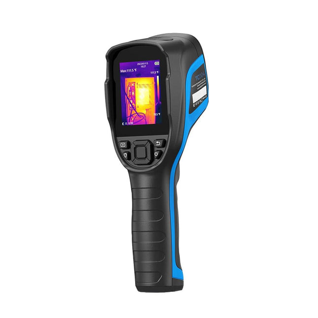
The TOPDON TC004 Thermal Imaging Camera offers a wide temperature range from -20°C to 350°C (-4°F to +662°F) with a 12-hour battery life. It features a high-resolution 256 x 192 pixel infrared camera, ensuring clear, detailed images.
With a thermal sensitivity of 0.05°C, it can detect subtle temperature changes. The camera automatically detects center, hot, and cold spots, enhancing visual temperature analysis. Its wide 56° field of view captures more in a single shot without needing focal adjustments.
The TC004 offers precise measurements with ±2°C accuracy, a NETD of less than 40 mK, and a resolution down to 0.1°C. It supports both standalone and PC modes, allowing users to upload and project images for easy analysis. The built-in LED light enables usage in low-light conditions, and the professional software simplifies data sharing.
Features
Wide Temp Ranging from −20°C to 350°C (−4°F to 662°F)
Real-time Photo and Video Recording
5 Color Palettes for More Possibilities
Tripod Mountable for a Stable View
High and Low Temperature Alarm
Monitor Temperature Change with Waveform Graphs
Long-lasting 12 Hour Battery Life
PC Image Analysis and Instant Projection
Built-in LED Light
Specifications
TC004
TC004 SE
TC004 Lite
Display
2.8" Color TFT (320 x 240 Pixels)
2.8" Color TFT (320 x 240 Pixels)
2.8" Color TFT (320 x 240 Pixels)
IR light resolution
256 x 192 Pixels
256 x 192 Pixels
160 x 120 Pixels
Spectral range
8~14 μm
8~14 μm
8~14 μm
FOV
52.5° x 39.5°
56° x 42°
40° x 30°
Storage
2 GB RAM + 16 GB TF card
32 GB Built-in
512 MB Built-in
Measuring range
−20~350°C (−4~662°F)
−20~550°C (−4~1022°F)
−20~550°C (−4~1022°F)
Temperature resolution
0.1°C (0.18°F)
0.1°C (0.18°F)
0.1°C (0.18°F)
Measuring modes
Center spot/hot spot/cold spot
Center spot/hot spot/cold spot
Center spot/hot spot/cold spot
Measuring accuracy
±2°C or ±2%
±2°C or ±2%
±2°C or ±2%
Frame rate
25 Hz
25 Hz
25 Hz
Focal length
3.2 mm (0.12")
3.2 mm (0.12")
2.6 mm (0.1")
NETD
<40 mK
<40 mK
<40 mK
Magnification
1x/2x/4x (digital zoom)
1x/2x/4x (digital zoom)
1x/2x/4x (digital zoom)
Tripod screw hole
Yes
Yes
Yes
High/Low temperature alarm
Yes
Yes
Yes
LED flashlight
Yes
Yes
No
Video recording
Yes
Yes
No
Auto shutdown
5 min, 10 min, 20 min, OFF
5 min, 10 min, 20 min, OFF
5 min, 10 min, 20 min, OFF
Battery
Built-in 5000 mAh battery
Built-in 5300 mAh battery
Built-in 2900 mAh battery
Charging time
4 h
4 h
4 h
Standby time
12 h
16 h (High Brightness)21 h (Low Brightness)
15 h
Operating system
Standalone use/Windows devices
Standalone use/Windows devices
Standalone use
PC-based analysis
Supports image analysis with PC
Yes
No
Dimensions
240 x 70 x 90 mm
240 x 70 x 90 mm
240 x 70 x 90 mm
Weight
520 g
520 g
520 g
Included
1x TOPDON TC004 Thermal Imaging Camera
1x USB Power Supply
4x Plugs (EU, UK, US, and AU)
1x USB Cable
1x Storage Bag
1x Manual
Downloads
Datasheet
Manual
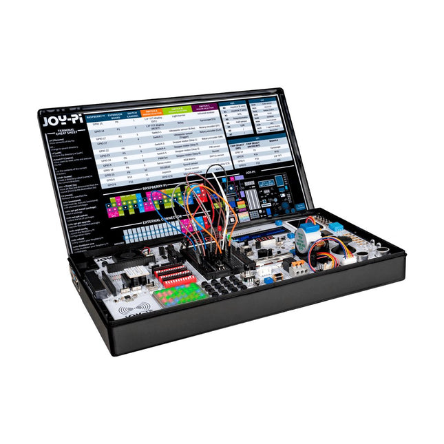
The Joy-Pi Advanced is a compact and powerful device that allows you to realize your projects quickly and easily. Whether you already have a lot of experience, or next to none, the Joy-Pi Advanced lets you unleash your creativity. Thanks to its compatibility with a wide range of platforms, including Raspberry Pi, Raspberry Pi Pico, Arduino Nano, BBC micro:bit, and NodeMCU ESP32, you can easily and quickly access your preferred platform.
In addition, the Joy-Pi Advanced features more than 30 stations, lessons, and modules, giving you an unlimited variety of ways to get your projects done. With the self-developed learning center, you can not only improve your skills but also create new projects. The learning center offers a wealth of information and tutorials that will guide you step by step through your projects.
Joy-Pi Advanced is characterized in particular by its intelligent switch units, which allow an extended use of the available pins. A total of three switch units are integrated, each equipped with 12 individual switches that provide precise control of the connected sensors and modules. This system solves the well-known problem of limited pin count that occurs with conventional microcontrollers. The switch units allow you to operate a large number of sensors and modules in parallel by switching them on and off individually. This simulates multiple pin assignment, allowing you to exploit the full power of your projects without compromising functionality.
By combining innovative adapter boards and the micro:bit slot, you can achieve seamless compatibility with a wide range of microcontrollers such as Raspberry Pi Pico, NodeMCU ESP32, micro:mit and Arduino Nano. The specially developed adapter boards are designed to perfectly match the respective microcontroller. By plugging the microcontroller onto the appropriate adapter board and then plugging it into the micro:bit slot, the Joy-Pi Advanced quickly and easily becomes compatible with the different microcontrollers. This allows seamless integration of your preferred platform and the ability to combine the strengths of the different microcontrollers in your projects. This way, you can fully focus on your creative projects without worrying about the compatibility of different microcontrollers. The Joy-Pi Advanced simplifies the development process and gives you the possibility to design your projects flexibly and individually.
Features
Highly integrated development platform & learning center
Fast, easy & wireless combination of various sensors & actuators
Installation option for Raspberry Pi 4
Compatible with various microcontrollers
Self-developed, didactic learning platform for Raspberry Pi & Windows
Specifications
Compatible to
Raspberry Pi 4, Arduino Nano, NodeMCU ESP32, BBC micro:bit, Raspberry Pi Pico
Installed sensors, actuators & components
39
Learning platform
Over 40 entries in the know-ledge database, 10 projects, 10 learning tasks, 14 visions
Displays
7-segment display, 16x2 display, 1.8“ TFT display, 0.96" OLED display, 8x8 RGB matrix
Sensors
DS18B20, shock sensor, hall sensor, barometer, sound sensor, gyroscope, PIR sensor, Light barrier, NTC, Light sensor, 6x touch sensor, color sensor, ultrasonic distance sensor, DHT11 temperature & humidity sensor
Control
Joystick, 5x switches, potentiometer, rotary encoder, 4x4 button matrix, relays, PWM fan
Motors
Servo interface, Stepper motor interface, Vibration motor
Measuring & conversion modules
Analog-Digital Converter, Level converter, voltmeter, Variable voltage supply
Other components
RTC real time clock, buzzer, EEPROM memory, infrared receiver, breadboard, RFID reader
Adapter boards
Adapter for NodeMCU ESP32, Arduino Nano & Raspberry Pi Pico, Board connectors for Raspberry Pi & External Boards
Electronic components
Infrared remote control, RFID chip, RFID card, 6x alligator clips, microSD card reader, servo motor, stepper motor, 32 GB microSD card
Components
40x resistors, 3x green LEDs, 3x yellow LEDs, 3x red LEDs, 1x transistor, 5x buttons, 1x potentiometer, 2x capacitors
Other accessories
Screw assortment, screwdriver, accessory storage bag, power supply & power cable, servo mount
Power supply
Built-in power supply: 36 W, 12 V, 3 A Case connector: Small device plug C8
Voltage outputs
12 V, 5 V, 3.3 V, Variable voltage output (2-11 V)
Data buses & signal outputs
I²C, SPI, Analog to digital converter
Battery (RTC)
CR2032
Dimensions
327 x 200 x 52 mm
Required
Raspberry Pi 4 with at least 2 GB RAM
Downloads
Joy-Pi website
Datasheet
Manual
MDP-P906 has a built-in cooling fan, and maximum output power of up to 300 W, which meets a wider range of testing needs and application scenarios. Through 2.4 GHz wireless communication, it can be connected to MDP-M01 Smart Digital Monitor module to realize the free combination of multiple channels of 300 W per channel.
MDP-P906 has the index, stability and reliability comparable to a professional power supply. It can output pure current, and provide powerful functions such as programmable output, timing output, timing control, automatic compensation, boost mode, etc., making itself a real cost-effective, smart and customized programmable linear DC power supply.
MDP-P906 adopts a precision CNC machined aluminum alloy shell, with fine workmanship, novel, mini and beautiful appearance, it completely subverts the rigid image of traditional desktop power supply. With stackable modular design and wireless communication function, MDP-P906 can work independently or paired, both on the workbench, and be carried out for on-site maintenance. MDP-P906 is a perfect solution for electronic engineer, especially field application engineers to meet different needs of power sources.
Built-in silent cooling fan, instant cooling, ensure a stable and efficient output!
Smart linear compensation, constant voltage & constant current
Positive & negative output, series boost, parallel current sharing
Applications
Universal tests and teaching experiments in R&D laboratory
Maintenance of digital products
Property verification and fault diagnosis of devices and circuits
Emergency power supply for model airplanes and vehicles
Power supply testing of RF and microwave circuits or modules
Quality control and quality inspection
Supply purified power for high-accuracy digital-analog hybrid circuits and Hi-Fi audio devices
Specifications
Input
DC 4.2-30 V/14 A (Max)QC 3.0/PD2.0, 20 V/5 A (Max)
Output
0-30 V/0-10 A, 300 W (Max)
Conversion efficiency
95%
Output resolution
10 mV/2 mA, up to 1 mV/1 mA via Display Control module
Output accuracy
0.03%+5 mV0.05%+2 mV
Adjustment rate
Load adjustment rate <±0.01%Power adjustment rate <±0.01%
Ripple and noise
<250 uVrms, 3 mVpp; 2 mArms
Transient response
<4 uS
Safety protections
Input over-voltage, under-voltage, reverse connection protection, output over-current, back-flow protection and over-temperature protection
Others
Automatically shut-down and enter micro-power modeSupport USB firmware upgrade
Dimensions
112 x 66 x 20 mm
Weight
181 g
Included
1x MDP-P906 Digital Power Supply
2x Output Cable
1x User Manual
Downloads
User Manual v1.1
Firmware v1.32
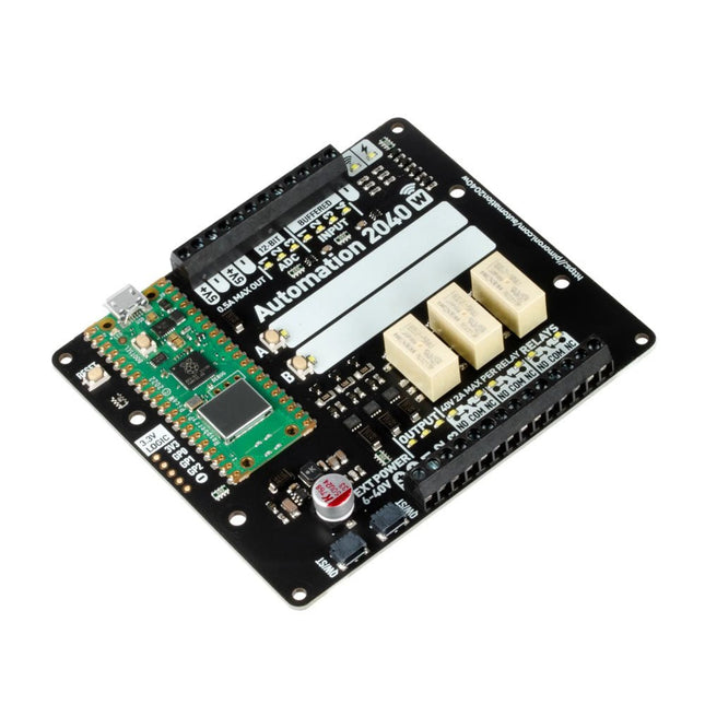
An all-in-one, Pico W powered industrial/automation controller with 2.46 GHz wireless connectivity, relays and a plethora of inputs and outputs. Compatible with 6 V to 40 V systems.
Automation 2040 W is a Pico W / RP2040 powered monitoring and automation board. It contains all the great features from the Automation HAT (relays, analog channels, powered outputs and buffered inputs) but now in a single compact board and with an extended voltage range so you can use it with more devices. Great for controlling fans, pumps, solenoids, chunky motors, electronic locks or static LED lighting (up to 40 V).
All the channels (and the buttons) have an associated indicator LED so you can see at a glance what's happening with your setup, or test your programs without having hardware connected.
Features
Raspberry Pi Pico W Aboard
Dual Arm Cortex M0+ running at up to 133 Mhz with 264 kB of SRAM
2 MB of QSPI flash supporting XiP
Powered and programmable by USB micro-B
2.4 GHz wireless
3x 12-bit ADC inputs up to 40 V
4x digital inputs up to 40 V
3x digital sourcing outputs at V+ (supply voltage)
4 A max continuous current
2 A max current at 500 Hz PWM
3x relays (NC and NO terminals)
2 A up to 24 V
1 A up to 40 V
3.5 mm screw terminals for connecting inputs, outputs and external power
2x tactile buttons with LED indicators
Reset button
2x Qw/ST connectors for attaching breakouts
M2.5 mounting holes
Fully assembled
No soldering required.
C/C++ and MicroPython libraries
Schematic
Dimensional drawing
Power
Board is compatible with 12 V, 24 V and 36 V systems
Requires supply 6-40 V
Can provide 5 V up to 0.5 A for lower voltage applications
Software
Pirate-brand MicroPython
Getting Started with Raspberry Pi Pico
MicroPython examples
MicroPython function reference
C++ examples
C++ function reference
Getting Started with Automation 2040 W
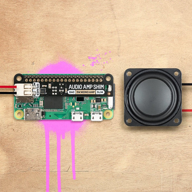
SHIM is an old Yorkshire term meaning 'Shove Hardware In Middle' - we use it for Raspberry Pi add-ons that are designed to be sandwiched between your Pi and a HAT or mini HAT. This one has a clever friction fit header that slips handily over your GPIO pins, doesn't need soldering*, and is easily removable. The MAX98357A combined DAC / amplifier chip takes high-quality digital audio from your Pi and amplifies it so it can be used with an unpowered speaker. The push-fit connectors make it straightforward to connect up your speaker, whether it's a bookshelf or floor-standing speaker, the speaker in an old radio, or any other speaker you might have laying around. Because Audio Amp SHIM adds no extra bulk to your Pi it's perfect for building into a compact enclosure - you could use it to make a tiny MP3 player to play local files or stream from services like Spotify, give a vintage radio the ability to play digital radio streams or incorporate bleepy noises into your very own retro handheld. It's also a handy way to add audio output to your Pi Zero or Pi 400! Please note: Raspberry Pi and speakers are not included with this board. Features MAX98357A DAC / amplifier chip Mono 3W audio out Push-fit speaker terminals SHIM-format board with friction-fit connectors 2x mounting holes (M2.5) for if you want to secure everything together with bolts Fully-assembled No soldering required (*unless you're using a Pi that comes without a header) Compatible with all 40-pin header Raspberry Pi models
Software The easiest way to get everything set up is to use Pimoroni's Pirate Audio software and installer which configures I2S audio, as well as installing Mopidy and our custom Pirate Audio plugins which will let you stream Spotify and play local files. Here's how to get started: Set an SD card up with the latest version of Raspberry Pi OS. Connect to Wi-Fi or a wired network. Open a terminal and type the following:git clone https://github.com/pimoroni/pirate-audiocd pirate-audio/mopidysudo ./install.sh
Reboot your Pi Downloads MAX98357A Datasheet Pirate Audio software Schematic
The SparkFun Qwiic OpenLog is the smarter and better looking cousin to the extremely popular OpenLog but now we've ported the original serial based interface to I²C! Thanks to the added Qwiic connectors, you can daisy chain multiple I²C devices and log them all without taking up your serial port. The Qwiic OpenLog can store, or 'log', huge amounts of serial data and act as a black box of sorts to store all the data that your project generates, for scientific or debugging purposes. Utilizing our handy Qwiic system, no soldering is required to connect it to the rest of your system. However, we still have broken out 0.1'-spaced pins in case you prefer to use a breadboard. Like its predecessor, the SparkFun Qwiic OpenLog runs off of an onboard ATmega328, running at 16 MHz thanks to the onboard resonator. The ATmega328 has been sure to feature the Optiboot bootloader loaded, which allows the OpenLog to be compatible with the “Arduino Uno” board setting in the Arduino IDE. It is important to be aware that the Qwiic OpenLog draws approximately 2 mA-6 mA in idle (nothing to record) mode, however, during a full record the OpenLog can draw 20 mA to 23 mA depending on the microSD card being used. The Qwiic OpenLog also supports clock stretching, which means it performs even better than the original and will record data up to 20,000 bytes per second at 400 kHz. As the receive buffer fills up this OpenLog will hold the clock line, letting the master know that it is busy. Once the Qwiic OpenLog is finished with a task, it releases the clock thus allowing the data to continue flowing without corruption. For even better performance the OpenLog Artemis is the tool you need, featuring logging speeds up to 500000 bps. Features Continuous data logging at 20,000 bytes per second without corruption Compatible with high speed 400 kHz I²C Compatible with 64 MB to 32 GB microSD cards (FAT16 or FAT32) Preloaded Uno bootloader so upgrading the firmware is as easy as loading a new sketch Valid I²C Addresses: 0x08 to 0x77 2x Qwiic Connectors Downloads Schematic Eagle Files Hookup Guide Arduino Library GitHub
The Raspberry Pi Compute Module 5 Development Kit provides an ideal platform for prototyping embedded solutions. This all-in-one kit contains the Compute Module 5, the Compute Module 5 IO Board and all necessary accessories to start your product design.
Compute Module 5 (CM5104032)
2.4 GHz quad-core 64-bit Arm Cortex-A76 CPU
VideoCore VII GPU, supporting OpenGL ES 3.1 and Vulkan 1.3
4 GB LPDDR4X-4267 SDRAM
32 GB MLC eMMC memory
1x Dual 4Kp60 HDMI display output
1x 4Kp60 HEVC decoder
1x Dual-band 802.11ac Wi-Fi and Bluetooth 5.0
2x USB 3.0 interfaces, supporting simultaneous 5 Gbps operation
1x Gigabit Ethernet, with IEEE 1588 support
2x 4-lane MIPI camera/display transceivers
1x PCIe 2.0 interface for fast peripherals
30 GPIOs, supporting 1.8 V or 3.3 V operation
Peripherals: UART, SPI, I²C, I²S, SDIO, and PWM
Compute Module 5 IO Board
1x Standard 40-pin GPIO
2x Full-size HDMI 2.0
2x 4-lane MIPI DSI/CSI-2 FPC (22-pin, 0.5 mm pitch cable)
2x USB 3.0
1x Gigabit Ethernet jack with PoE+ support (requires a separate Raspberry Pi PoE+ HAT+)
1x M.2 M-key PCIe socket (for 2230, 2242, 2260 and 2280 modules)
1x microSD card socket (for use with Lite modules)
1x RTC battery socket
1x 4-pin fan connector
Compute Module 5 IO Case
The metal case transforms the IO Board into a fully enclosed, industrial-grade computer. Designed specifically for the Raspberry Pi Compute Module 5, the IO Case features a built-in fan that connects to the IO Board's 4-pin fan connector, ensuring enhanced thermal performance.
Included
1x Raspberry Pi Compute Module 5 (Wireless, 4 GB RAM, 32 GB eMMC)
1x Raspberry Pi Compute Module 5 IO Board (supplied pre-fitted inside the IO Case)
1x Raspberry Pi Compute Module 5 IO Case
1x Raspberry Pi Compute Module 5 Cooler
1x Raspberry Pi Antenna Kit
1x Raspberry Pi 27 W USB-C PD Power Supply (EU)
2x Raspberry Pi HDMI to HDMI cables
1x Raspberry Pi USB-A to USB-C cable
Downloads
Datasheet (Compute Module 5)
Datasheet (IO Board)
Datasheet (IO Case)
Datasheet (Cooler)
Datasheet (Antenna Kit)
The FLIRC Raspberry Pi Zero Case is compatible with Raspberry Pi Zero W and the newer Raspberry Pi Zero 2 W.
The design of the FLIRC Zero Case is based on the original FLIRC case. As with the original, the aluminum housing serves as protection and, thanks to the contact point on the processor, as a passive cooler. Ideal for silent operation.
In addition to a normal cover that encloses and protects the Raspberry Pi Zero, there is a second cover that allows access to the GPIO pins through a small opening.
Enhance your Arduino projects with the Ardi Relay Shield, a versatile 4-channel optoisolated relay board. Designed to handle AC (250 V, 7 AMP) and DC (30 V, 10 AMP) power, this shield empowers you to easily control a wide range of electrical devices.
Equipped with four LED relay indicators, the Ardi Relay Shield provides visual feedback on the status of each relay, ensuring you stay informed and in control of your circuit. The shield also features four 3-pin screw terminals (NC, NO, COM) for convenient and secure connections.
Designed in the Arduino form factor, this shield seamlessly integrates with your Arduino Uno, allowing you to expand its capabilities and create interactive projects. Whether you're automating home appliances, building intelligent systems, or working on industrial applications, the Ardi Relay Shield is the reliable choice for robust and efficient relay control.
Features
4-channel optoisolated relay so better electrical isolation between High and Low side voltage.
4x Relay shield compatible with both 3.3 V and 5 V MCU
Onboard 4 Status LED to indicate each relay ON/OFF State
High-quality relays
Provides NO/NC interfaces with Screw terminals.
Mounts directly onto ArdiPi, Ardi32 or other Arduino compatible boards
Specifications
Max Switching Voltage: 250 V AC/30 V DC
Max Switching Current: 7 A/10 A
Max Switching Power: 2770 VA/240 W
Frequency: 1 Hz
Initial Contact Resistance: 50 mΩ max at 6 V DC/1 A
Operate Time: 10ms max
Release Time: 5ms max
Life Expectancy Electrical: 100,000 operations (rated load)
Life Expectancy Mechanical: 10,000,000 operations (no load)
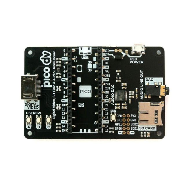
This board is an all-digital conversion of Raspberry Pi's VGA reference design, great for if you want to start hacking on video and/or audio output from a Raspberry Pi Pico and piping it straight into a modern monitor.Features
HDMI connector
PCM5100A DAC for line out audio over I²S (datasheet)
SD card slot
Reset button
Socket headers to install your Raspberry Pi Pico
Three user-controllable switches
Rubber feet
Compatible with Raspberry Pi Pico
No soldering required (as long as your Pico has header pins attached)
Programmable with C/C++
Note: Raspberry Pi Pico is not included. Your Pico will need to have pin headers soldered to it (with the pins pointing downwards) to attach to our add-on boards.Downloads
Schematic
GitHub
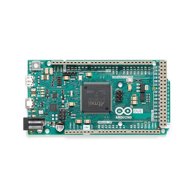
The board contains everything needed to support the microcontroller; simply connect it to a computer with a micro-USB cable or power it with an AC-to-DC adapter or battery to get started. The Due is compatible with all Arduino shields that work at 3.3V and are compliant with the 1.0 Arduino pinout.
The Due follows the 1.0 pinout:
TWI: SDA and SCL pins that are near to the AREF pin.
IOREF: allows an attached shield with the proper configuration to adapt to the voltage provided by the board. This enables shield compatibility with a 3.3V board like the Due and AVR-based boards which operate at 5V.
An unconnected pin, reserved for future use.
Specifications
Operating Voltage
3.3 V
Input Voltage
7-12 V
Digital I/O
54
Analog Input Pins
12
Analog Output Pins
2 (DAC)
Total DC Output Current on all I/O Lines
130 mA
DC Current per I/O Pin
20 mA
DC Current for 3.3 V Pin
800 mA
DC Current for 5 V Pin
800 mA
Flash Memory
512 KB all available for the user applications
SRAM
96 KB
Clock Speed
84 MHz
Length
101.52 mm
Width
53.3 mm
Weight
36 g
Please note: Unlike most Arduino boards, the Arduino Due board runs at 3.3V. The maximum voltage that the I/O pins can tolerate is 3.3V. Applying voltages higher than 3.3V to any I/O pin could damage the board.
This rugged, passive aluminum cooling case is made specifically for the Raspberry Pi 5 and offers a sleek design that ensures both durability and effective heat dissipation. The case is exclusively compatible with the Raspberry Pi 5 and provides a passive cooling solution, eliminating the need for a fan while still managing heat efficiently.
Features
High quality aluminum construction: Made from high quality aluminum, this case is built to last and withstand regular use.
Optimized heat dissipation: The passive cooling design uses the aluminum structure to keep your Raspberry Pi 5 cool without the need for a fan.
Full port accessibility: Every port on the Raspberry Pi 5 is easily accessible, from the microSD card slot to USB, micro HDMI and GPIO ports.
GPIO cable support: A reserved interface for the GPIO cable ensures that you can continue to use this important function without having to remove the case.
Convenient power switch: The case has an integrated power switch that allows you to turn your device on and off.
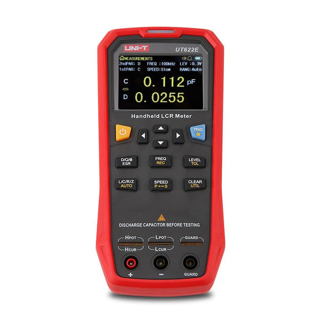
The UT622E handheld LCR meter features powerful functions, high accuracy, fast speed, and long standby time. With a clear and intuitive 2.8-inch TFT LCD display, large-capacity rechargeable battery, and 100 kHz test frequency, the meter can be used for longstanding accurate and convenient measurement in any occasion.
It is suitable for the measurement and screening of inductance, capacitance, and resistance in laboratories, production lines, maintenance points, etc.
Features
Max. test frequency: 100 kHz
Accuracy: 0.1%
Display count: 99999
Max. test rate: 20 times/s
DCR: Yes
Connectivity: Mini-USB
Display: 2.8" TFT LCD
Specifications
Testfrequency
100 Hz, 120 Hz, 1 kHz, 10 kHz, 100 kHz
Test level
0.1 Vmrs, 0.3 Vrms, 1 Vrms
Output impedance
100 Ω
Measurement parameters
Primary: L/C/R/Z/DCRSecondary: D/Q/Θ/ESR
DSR speed test
Fast (20 times/s), medium (5 times/s), or slow (2 times/s)
Range
Auto/Hold
Tolerance range
1%~20%
Equivalent mode
Series/Parallel
Clearing connection
Open/Short circuit
Fuse of test ports
0.1 A/250 V
Communication interface
Mini-USB
MAX reading of primary parameters
99999
MIN resolution
0.0001
Maximum accuracy
0.10%
L
0.00 µH~99.999 H
C
0.00 pF~99.999 mF
Z/R
0.0000 Ω~9.9999 MΩ
ESR
0.0000 Ω~999.99 Ω
D
0.0000~9.9999
Q
0.0000~99999
Θ
-179.9°~179.9°
DCR
0.01 mΩ~20.000 MΩ
Power supply
3.7 V/1800 mAh lithium polymer battery
Display
2.8" TFT LCD (320x240)
Dimensions
93 x 192 x 44 mm
Weight
420 g
Included
UT622E LCR meter
Short circuit board
Four-terminal kelvin test leads
USB cable
Manual
Downloads
Datasheet
Manual
Software
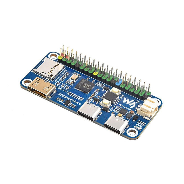
Waveshare RP2040-PiZero is a high-performance and cost-effective microcontroller board with onboard DVI interface, TF card slot and PIO-USB port, compatible with Raspberry Pi 40-pin GPIO header, easy to develop and integrate into the products.
Features
RP2040 microcontroller chip designed by Raspberry Pi
Dual-core ARM Cortex M0+ processor, flexible clock running up to 133 MHz
264 KB of SRAM, and 16 MB of onboard Flash memory
Onboard DVI interface can drive most HDMI screens (DVI compatibility required)
Supports using as a USB host or slave via onboard PIO-USB port
Onboard TF card slot for reading and writing TF card
Onboard Lithium battery recharge/discharge header, suitable for mobile scenarios
USB 1.1 with device and host support
Drag-and-drop programming using mass storage over USB
Low-power sleep and dormant modes
2x SPI, 2x I²C, 2x UART, 4x 12-bit ADC, 16x controllable PWM channels
Accurate clock and timer on-chip
Temperature sensor
Accelerated floating-point libraries on-chip
Downloads
Wiki
Programmable Robot Kit with 344 Parts
variAnt runs and acts almost like its natural role model. Its patented walking mechanism was especially developed for the fine-boned anatomy of an insect and is driven by compact micro-geared motors.
The autonomous robot ant explores its entire environment with the help of 12 analogue sensors. This allows it to detect obstacles, markings, movements or light sources based on the slightest differences in brightness.
The control unit in the rear, which is equipped with a nano-board, offers a wide range of flexible connection options in combination with the breadboard in the head. After the exciting setup, ready-made and expandable code modules ensure an easy and quick introduction to Arduino programming up to the first experiments with artificial intelligence.
The kit already comes with a USB rechargeable 9 V Li-Ion battery, which supplies the robot ant with power for at least 5 hours.
Robot ant as a programmable kit
Compatible with Arduino IDE
Patented mechanics and sensors
Features of variAnt
24 high-quality acrylic parts
12 variable environmental sensors
2 reed sensors for step counting
2 freely programmable buttons
8 freely usable digital I/Os
15 pluggable status LEDs
Specifications
Content: 344 parts
Construction time: about 4-8 hours (no soldering required)
Dimensions: 25 x 22.5 x 9 cm (L x W x H)
Weight: 210/232 g (without/with battery)
Necessary tools
PC or tablet, micro-USB and USB-C cable, flat pliers, diagonal pliers, carpet knife, permanent marker
Downloads
Manual
Arduino library
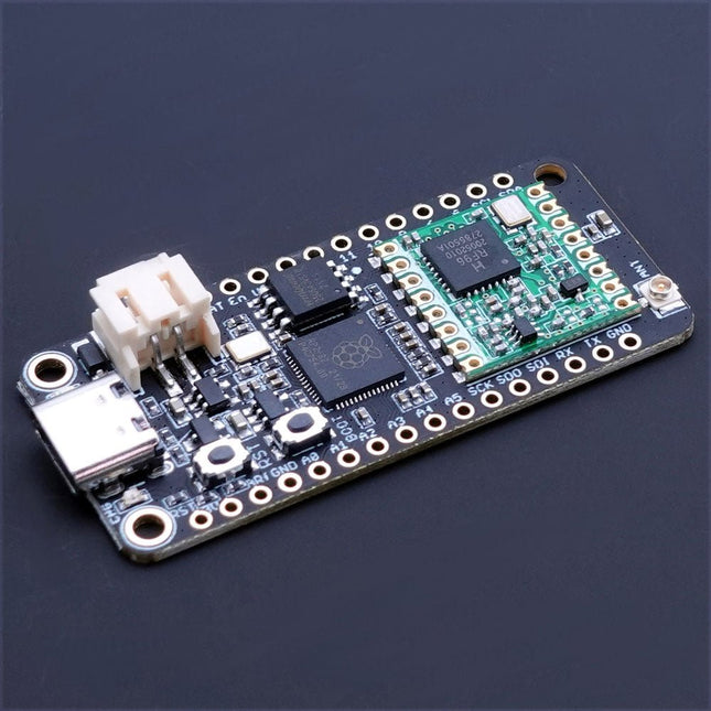
The Challenger RP2040 LoRa is an Arduino/CircuitPython compatible Adafruit Feather format microcontroller board based on the Raspberry Pi Pico (RP2040) chip.The transceiver features a LoRa long range modem that provides ultra-long range spread spectrum communication and high interference immunity whilst minimizing current consumption.LoRaThe integrated module LoRa module (RFM95W) can achieve a sensitivity of over -148 dBm utilizing a low cost crystal and bill of materials. The high sensitivity combined with the integrated +20 dBm power amplifier yields industry leading link budget making it optimal for any application requiring range or robustness. LoRa also provides significant advantages in both blocking and selectivity over conventional modulation techniques, solving the traditional design compromise between range, interference immunity and energy consumption.The RFM95W is connected to the RP2040 via SPI channel 1 and a few GPIO’s that is required for signaling. A U.FL connector is used to attach your LoRa antenna to the board.
168 dB maximum link budget
+20 dBm – 100 mW constant RF output vs. V supply
+14 dBm high efficiency PA
Programmable bit rate up to 300 kbps
High sensitivity: down to -148 dBm
Bullet-proof front end: IIP3 = -12.5 dBm
Excellent blocking immunity
Low RX current of 10.3 mA, 200 nA register retention
Fully integrated synthesizer with a resolution of 61 Hz
FSK, GFSK, MSK, GMSK, LoRaTM and OOK modulation
Built-in bit synchronizer for clock recovery
Preamble detection
127 dB Dynamic Range RSSI
Automatic RF Sense and CAD with ultra-fast AFC
Packet engine up to 256 bytes with CRC
Specifications
Microcontroller
RP2040 from Raspberry Pi (133 MHz dual-core Cortex-M0)
SPI
Two SPI channels configured (second SPI connected to RFM95W)
I²C
One I²C channel configured
UART
One UART channel configured
Analog inputs
4 analog input channels
Radio module
RFM95W from Hope RF
Flash memory
8 MB, 133 MHz
SRAM memory
264 KB (divided into 6 banks)
USB 2.0 controller
Up to 12 MBit/s full speed (integrated USB 1.1 PHY)
JST Battery connector
2.0 mm pitch
On board LiPo charger
450 mA standard charge current
Dimensions
51 x 23 x 3,2 mm
Weight
9 g
Downloads
Datasheet
Design files
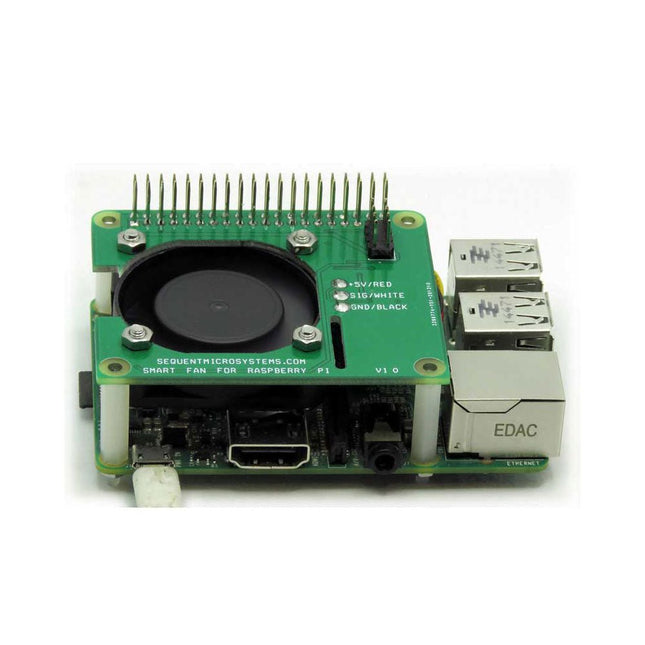
Raspberry Pi cooling is a must. From the simplest passive heat sink, through elaborate fan blowers and even to an exotic water-cooled idea, many options are available.
Sequent Microsystems Smart Fan has the form factor of the Raspberry Pi HAT. Its own tinny 32-bit processor receives commands from Raspberry Pi through the I²C interface. A step-up power supply converts the 5 V provided by Raspberry Pi to 12 V, ensuring precise speed control. Using pulse width modulation, it powers the fan just enough to maintain a constant temperature of the Raspberry Pi processor.
The Smart Fan preserves all the GPIO pins, allowing any number of cards to be stacked on top of Raspberry Pi. If another add-on card has to dissipate power, a secondary Smart Fan can be added to the stack.
DIN-Rail Mounting
Together with multiple add-on cards, the Smart Fan can be installed on the DIN-Rail, for sturdy industrial applications.
Stack Level Jumper
Two Smart Fans can be installed on top of each Raspberry Pi. The assumption is that you have one more card in the stack which requires cooling. The bottom side of the Smart Fan has a jumper which needs to be installed on the second fan, in order for the Raspberry Pi to differentiate the two I²C addresses.
Features
40 x 40 x 10 mm fan with 6 CFM airflow
Step-up 12 V power supply for precise fan speed control
PWM Controller modulates the fan to keep constant Pi temperature
Draws less than 100 mA of power
Stackable to itself, 2 fans can be added to Raspberry Pi
Fully stackable allows adding other cards to Raspberry Pi
Uses only I²C interface, leaves full use of all GPIO pins
Super quiet and efficient
Included
Smart Fan HAT
40 x 40 x 10 mm Fan with mounting Screws
Mounting Hardware
Downloads
User's Guide
Open Source Hardware Schematic
2D CAD Drawing
Command line
Python Libraries
Node-Red Nodes