Trade products
-
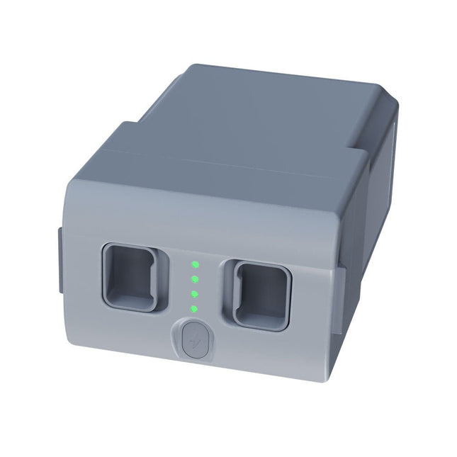
Unitree Unitree Go2 Spare Battery (15,000 mAh)
With a capacity of 15,000 mAh, the Unitree Go2 battery provides a robust power source that enables your robot to complete tasks with ease. Whether for complex exploration, research projects, or fun excursions, this powerful battery delivers the energy your robot needs. The runtime of the Unitree Go2 battery varies depending on the application and usage. Based on the functions and activities employed, the battery can offer between 2 to 4 hours of operation. This flexibility allows you to customize the robot as needed, enabling longer exploration missions or more extensive projects. The Unitree Go2 battery is a reliable companion for your robotics adventures. With its impressive capacity and adaptable runtime, it ensures your robot performs powerfully and with endurance, without frequent recharging. Whether you need the Unitree Go2 battery as a replacement or an upgrade for your robot, this powerful energy storage solution provides the perfect balance of performance and reliability. Specifications Rated voltage: DC 28.8 V Limited charging voltage: DC 33.6 V Charging current: 9 A Rated capacity: 15,000 mAh, 432 Wh Standard: IS 16046 (Part 2) / IEC 62133-2 Self-developed battery management system (BMS) Dimensions: 120 x 80 x 182 mm Functions: Power indicator Self-discharge protection of battery storage Equilibrium charge protection Overcharge protection Discharge protection Short circuit protection Battery charge detection protection
€ 795,00
Best Price
-
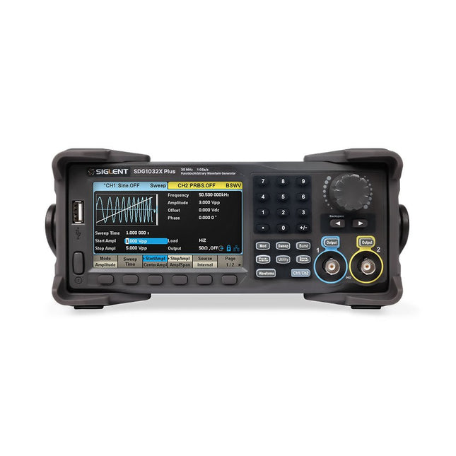
Siglent Siglent SDG1032X Plus 2-ch Arbitrary Waveform Generator (30 MHz)
The Siglent SDG1032X Plus is a high-performance dual-channel function/arbitrary waveform generator with a 30 MHz max frequency, 16-bit resolution, and 1 GSa/s sampling rate for superior signal fidelity. It features TrueArb for low-distortion waveforms, EasyPulse for jitter-free pulses, and robust sequence playback. With ±10 V amplitude, a 4.3" display, and versatile modulation, it's a reliable choice for engineers and researchers. Features Dual Channels: Independent output with maximum frequency of 30 MHz High Sampling Rate: 1 GSa/s for precise waveform generation High Vertical Resolution: 16-bit resolution for accurate signal reproduction TrueArb Technology: Generates low-distortion arbitrary waveforms with high fidelity EasyPulse Technology: Produces jitter-free square and pulse signals with fine control over rise/fall times Arbitrary Waveform Length: Supports up to 8 Mpts per channel for complex waveform design Wide Amplitude Range: ±10 V maximum output amplitude Built-in Modulation Functions: AM, FM, PM, PWM, PSK, FSK, ASK, and more Multi-Pulse Output: Enables measurement of power equipment switching parameters PRBS Pattern Generation: Supports up to 40 Mbps for advanced testing needs Sweep and Burst Modes: Flexible test capabilities with adjustable parameters Sequence Playback Function: Stores and plays back complex waveforms efficiently Frequency Counter: Measures frequencies up to 200 MHz with high precision User-Friendly Display: 4.3" color LCD with a clear interface Remote Control Support: Built-in WebServer for control via a web browser Compact Design: Portable and space-saving form factor Specifications Bandwidth 30 MHz Channels 2 Sampling rate 1 GSa/s (4x Interpolation) Vertical resolution 16 bits (per channel) Waveform length 8 Mpts Max. amplitude ±10 V Display 4.3" color TFT LCD (480 x 272) Interfaces USB Host, USB Device, LAN Dimensions 260 x 107 x 296 mm Weight 4.35 kg Included 1x Siglent SDG1032X Plus Arbitrary Function Generator 1x Power Cord 1x USB Cable 1x Guarantee Card 1x Quick Start Guide Downloads Datasheet User Manual Programming Guide Software
€ 446,49
-

Siglent Siglent SPD4306X 4-ch DC Power Supply (400 W)
The Siglent SPD4306X is a 4-channel DC Linear Programmable Power Supply equipped with a 4.3-inch TFT-LCD display, friendly human-machine interface, and excellent performance indicators. Real-time waveform display provides engineers with an informative user interface. SPD4306X offers a total output power of 400 W with a resolution of 1 mV/1 mA. The maximum voltage and current for each channel are as follows: CH1: 15 V/1.5 A CH2: 30 V/6 A CH3: 30 V/6 A CH4: 15 V/1 A Features Rated output power: 400 W Rated voltage: 32 V, 12 V, 30 V Up to four high-precision power supplies with independent controllable outputs, supporting CH2 and CH3 series and parallel connections Clear graphical interface with waveform and timer display modes 5-digit voltage and current display with minimum resolution of 1 mV, 1 mA Fast output response time: <50us The high current channel support remote voltage compensation sense function. The maximum compensation voltage is 0.6 V Overvoltage protection and overcurrent protection or safe and accurate operation Equipped with a 4.3-inch TFT-LCD display (480 x 272 resolution) USB and LAN standard communication USB-GPIB module is optional Excellent channel density with up to 4 channels in a 3U half rack package Internal data storage for setups and parameters Embedded Web Server with instrument communication that doesn’t require software installation Fully SCPI programming command set support as well as a LabView driver for remote control and system automation Specifications SPD4323X SPD4121X SPD4306X Channel Output CH1: Voltage 0 to 6 V Current 0 to 3.2 ACH2: Voltage 0 to 32 V Current 0 to 3.2 ACH3: Voltage 0 to 32 V Current 0 to 3.2 ACH4: Voltage 0 to 6 V Current 0 to 3.2 A CH1: Voltage 0 to 15 V Current 0 to 1.5 ACH2: Voltage 0 to 12 V Current 0 to 10 ACH3: Voltage 0 to 12 V Current 0 to 10 ACH4: Voltage 0 to 15 V Current 0 to 1.5 A CH1: Voltage 0 to 15 V Current 0 to 1.5 ACH2: Voltage 0 to 30 V Current 0 to 6 ACH3: Voltage 0 to 30 V Current 0 to 6 ACH4: Voltage 0 to 15 V Current 0 to 1 A Resolution 1 mV, 1 mA 1 mV, 1 mA 1 mV, 1 mA Setting Accuracy Voltage: ±(0.03% of reading+10) mV, Current: ±(0.3% of reading+10) mA Voltage: ±(0.03% of reading+10) mV, Current: ±(0.3% of reading+10) mA Voltage: ±(0.03% of reading+10) mV, Current: ±(0.3% of reading+10) mA Readback Accuracy Voltage: ±(0.03% of reading+10) mV, Current: ±(0.3% of reading+10) mA Voltage: ±(0.03% of reading+10) mV, Current: ±(0.3% of reading+10) mA Voltage: ±(0.03% of reading+10) mV, Current: ±(0.3% of reading+10) mA Display 4.3" TFT-LCD 5-digit voltage and current display 4.3" TFT-LCD 5-digit voltage and current display 4.3" TFT-LCD 5-digit voltage and current display Output power 240 W 285 W 400 W Included 1x Siglent SPD4306X Power Supply 1x Power cord (EU) 1x Output test cord (3 A) 1x USB cable 1x Quick start guide Downloads Datasheet Manual Quick start
€ 1.101,10
-
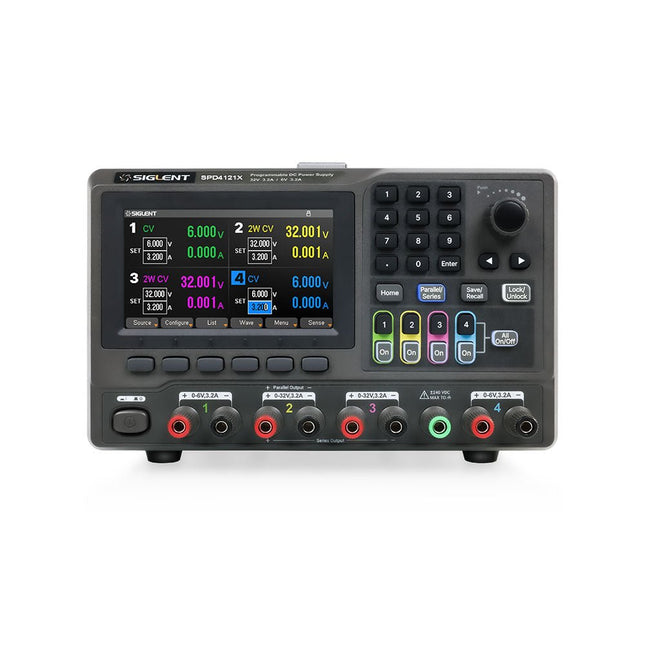
Siglent Siglent SPD4121X 4-ch DC Power Supply (285 W)
The Siglent SPD4121X is a 4-channel DC Linear Programmable Power Supply equipped with a 4.3-inch TFT-LCD display, friendly human-machine interface, and excellent performance indicators. Real-time waveform display provides engineers with an informative user interface. SPD4121X offers a total output power of 285 W with a resolution of 1 mV/1 mA. The maximum voltage and current for each channel are as follows: CH1: 15 V/1.5 A CH2: 12 V/10 A CH3: 12 V/10 A CH4: 15 V/1.5 A Features Rated output power: 285 W Rated voltage: 32 V, 12 V, 30 V Up to four high-precision power supplies with independent controllable outputs, supporting CH2 and CH3 series and parallel connections Clear graphical interface with waveform and timer display modes 5-digit voltage and current display with minimum resolution of 1 mV, 1 mA Fast output response time: <50us The high current channel support remote voltage compensation sense function. The maximum compensation voltage is 0.6 V Overvoltage protection and overcurrent protection or safe and accurate operation Equipped with a 4.3-inch TFT-LCD display (480 x 272 resolution) USB and LAN standard communication USB-GPIB module is optional Excellent channel density with up to 4 channels in a 3U half rack package Internal data storage for setups and parameters Embedded Web Server with instrument communication that doesn’t require software installation Fully SCPI programming command set support as well as a LabView driver for remote control and system automation Specifications SPD4323X SPD4121X SPD4306X Channel Output CH1: Voltage 0 to 6 V Current 0 to 3.2 ACH2: Voltage 0 to 32 V Current 0 to 3.2 ACH3: Voltage 0 to 32 V Current 0 to 3.2 ACH4: Voltage 0 to 6 V Current 0 to 3.2 A CH1: Voltage 0 to 15 V Current 0 to 1.5 ACH2: Voltage 0 to 12 V Current 0 to 10 ACH3: Voltage 0 to 12 V Current 0 to 10 ACH4: Voltage 0 to 15 V Current 0 to 1.5 A CH1: Voltage 0 to 15 V Current 0 to 1.5 ACH2: Voltage 0 to 30 V Current 0 to 6 ACH3: Voltage 0 to 30 V Current 0 to 6 ACH4: Voltage 0 to 15 V Current 0 to 1 A Resolution 1 mV, 1 mA 1 mV, 1 mA 1 mV, 1 mA Setting Accuracy Voltage: ±(0.03% of reading+10) mV, Current: ±(0.3% of reading+10) mA Voltage: ±(0.03% of reading+10) mV, Current: ±(0.3% of reading+10) mA Voltage: ±(0.03% of reading+10) mV, Current: ±(0.3% of reading+10) mA Readback Accuracy Voltage: ±(0.03% of reading+10) mV, Current: ±(0.3% of reading+10) mA Voltage: ±(0.03% of reading+10) mV, Current: ±(0.3% of reading+10) mA Voltage: ±(0.03% of reading+10) mV, Current: ±(0.3% of reading+10) mA Display 4.3" TFT-LCD 5-digit voltage and current display 4.3" TFT-LCD 5-digit voltage and current display 4.3" TFT-LCD 5-digit voltage and current display Output power 240 W 285 W 400 W Included 1x Siglent SPD4121X Power Supply 1x Power cord (EU) 1x Output test cord (3 A) 1x USB cable 1x Quick start guide Downloads Datasheet Manual Quick start
€ 871,20
-

Holybro Holybro QAV 250 ARF Drone Kit
The QAV250 Kit is the perfect way to get started developing on either PX4 or Ardupilot. It pairs a carbon fiber 250 racing frame and essential electronics with Pixhawk 6C mini autopilot. The kit is easy to assemble. No soldering needed. Specifications Micro Power Module (PM06 v2) Motors: 2207 KV1950 Wheelbase: 250 mm Dimensions: 198 x 235 x 70 mm Weight: 347 g Included Carbon fiber 250 airframe with hardware Micro Power Module (PM06 v2) Motors: 2207 KV1950 5' Plastic Props Fully assembled Power Management Board with ESCs (BLHeli S ESC 20A) Battery Straps Note: LiPo battery is not included.
€ 214,95
Best Price
-
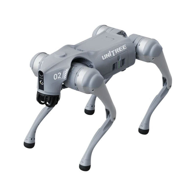
Unitree Unitree Go2 Edu Plus Quadruped Robot
Temporary Delay in the Delivery of Unitree Robots Like many other suppliers, we are currently experiencing delays in the delivery of Unitree robots. A shipment from our supplier is currently held in customs, which has unfortunately led to later-than-planned deliveries for previously placed orders. We are actively working with our supplier to resolve this issue and expect more clarity soon, but at this time, we cannot provide any guarantees. Additionally, a new shipment is already on its way, though it will take some time to arrive. Since other suppliers are facing similar challenges, switching to a different provider is unlikely to result in a faster solution. Our top priority remains fulfilling existing orders. If you have any questions or would like to update your order, please do not hesitate to contact our customer service team. We will keep you informed of any further developments. Unitree Go2 series consists of quadruped robots for the research & development of autonomous systems in the fields of human-robot interaction (HRI), SLAM & transportation. Due to the four legs, as well as the 12DOF, this robot can handle a variety of different terrains. The Go2 comes with a perfected drive & power management system, which enables a speed (depending on the version) of up to 3.7 m/s or 11.88 km/h with an operating time of up to 4 hours. Furthermore, the motors have a torque of 45 N.m at the body/thighs and at the knees, which also allow jumps or backflips. Features Super Recognition System: 4D LIDAR L1 Max Running Speed: approx. 5 m/s Peak Joint Torque: approx. 45 N.m Wireless Module: WiFi 6/Bluetooth/4G Ultra-long battery Endurance: approx. 2-4 h (long battery life measured in real life) Intelligent Side-follow System: ISS 2.0 Specifications Tracking module: Remote-controlled or automatic tracking Front camera: Image tansmission Resolution 1280x720, FOV 120°, Ultra wide angle lens deliver rich clarity Front lamp: Brightly lights the way ahead 4D LiDAR L1: 360°x90° omnidirectional ultra-wide-angle scanning allows automatic avoidance with small blind spot and stable operation 12 knee joint motors: Strong and powerful, Beautiful and simple, Brandy new visual experience Intercom microphone: Effective communication with no scenario restrictions Self-retracting strap: Easy to carry and load things More stable, more powerful with advanced devices: 3D LiDAR, 4G ESIM Card, WiFi 6 with Dual-band, Bluetooth 5.2 for stable connection and remote control Powerful Computing Core: Motion controller, High-performance ARM processor, Improved Al algorithm processor, External ORIN NX/NANO Smart battery: Standard 8000 mAh battery, Long-endurance 15000 mAh battery, Protection from over-temp, overcharge and short-circuit Speaker for music play: Listen to music as your pleasure Unitree Go2 Variants The Go2 impresses not only with its technical capabilities, but also with a modern and slim design that gives it a futuristic look and makes it a real eye-catcher. The Go2 Air is specially designed for demos and presentations. With its basic features, it offers a solid basis for demonstrating the movement capabilities and functionality of a four-legged robot. Important: The Go2 Air is delivered without a controller. This can be purchased optionally. With a powerful 8-core high-performance CPU, the Pro and Edu offer impressive computing power required for complex tasks and demanding calculations. This enables faster and more efficient data processing and makes the Pro and Edu a reliable partner for your projects. From the Edu version onwards, the Go2 is programmable and opens up endless possibilities for developing and researching your own robotics applications. The Go2 is also able to handle a step height of up to 14 cm. This makes it an ideal tool for research, education and entry into the world of robotics. The Go2 Edu comes with a remote controller that gives you easy and intuitive control. You also get a docking station with impressive computing power of 100 TOPS, which is equipped with powerful AI algorithms and offers you technical support. Go2 Edu is equipped with a powerful 15000 mAh battery that gives it an impressive runtime of up to 4 hours. This long operating time allows the robot to carry out longer exploration missions and complete demanding tasks. Model Comparison Air Pro Edu/Edu Plus Dimensions (standing) 70 x 31 x 40 cm 70 x 31 x 40 cm 70 x 31 x 40 cm Dimensions (crouching) 76 x 31 x 20 cm 76 x 31 x 20 cm 76 x 31 x 20 cm Material Aluminium alloy + High strength engineering plastic Aluminium alloy + High strength engineering plastic Aluminium alloy + High strength engineering plastic Weight (with battery) about 15 kg about 15 kg about 15 kg Voltage 28~33.6 V 28~33.6 V 28~33.6 V Peaking capacity about 3000 W about 3000 W about 3000 W Payload ≈7 kg (MAX ~ 10 kg) ≈8 kg (MAX ~ 10 kg) ≈8 kg (MAX ~ 12 kg) Speed 0~2.5 m/s 0~3.5 m/s 0~3.7 m/s (MAX ~ 5 m/s) Max Climb Drop Height about 15 cm about 16 cm about 16 cm Max Climb Angle 30° 40° 40° Basic Computing Power N/A 8-core High-performance CPU 8-core High-performance CPU Aluminum knee joint motor 12 set 12 set 12 set Intra-joint circuit (knee) ✓ ✓ ✓ Joint Heat Pipe Cooler ✓ ✓ ✓ Range of Motion Body: −48~48° Body: −48~48° Body: −48~48° Thigh: −200°~90° Thigh: −200°~90° Thigh: −200°~90° Shank: −156°~−48° Shank: −156°~−48° Shank: −156°~−48° Max Torque N/A about 45 N.m about 45 N.m Super-wide-angle 3D LiDAR ✓ ✓ ✓ Wireless Vector Positioning Tracking Module N/A ✓ ✓ HD Wide-angle Camera ✓ ✓ ✓ Foot-end force sensor N/A N/A ✓ Basic Action ✓ ✓ ✓ Auto-scaling strap N/A ✓ N/A Upgraded Intelligent OTA ✓ ✓ ✓ RTT 2.0 Image Transmission ✓ ✓ ✓ App Basic Remote Control ✓ ✓ ✓ App Data Viewing ✓ ✓ ✓ App Graphical Programme ✓ ✓ ✓ Front Lamp (3 W) ✓ ✓ ✓ WiFi 6 with Dual-band ✓ ✓ ✓ Bluetooth 5.2/4.2/2.1 ✓ ✓ ✓ 4G Module N/A CN/GB CN/GB Voice Function N/A ✓ ✓ Music Playback N/A ✓ ✓ ISS 2.0 Intelligent side-follow system N/A ✓ ✓ Intelligent detection and avoidance ✓ ✓ ✓ Secondary development N/A N/A ✓ Manual controller Optional Optional ✓ High computing power module N/A N/A Edu: 40 TOPS computing power Edu Plus: 100 TOPS computing power NVIDIA Jetson Orin (optional) Smart Battery Standard (8000 mAh) Standard (8000 mAh) Long endurance (15000 mAh) Battery Life 1-2 h 1-2 h 2-4 h Charger Standard (33.6 V, 3.5 A) Standard (33.6 V, 3.5 A) Fast charge (33.6 V, 9 A) Included 1x Unitree Go2 Edu Plus 1x Unitree Go2 Remote Controller 1x Unitree Go2 Battery (15000 mAh) 1x Unitree Docking station with 100 TOPS computing power Downloads Documentation iOS/Android apps GitHub
€ 14.999,00
Best Price
-
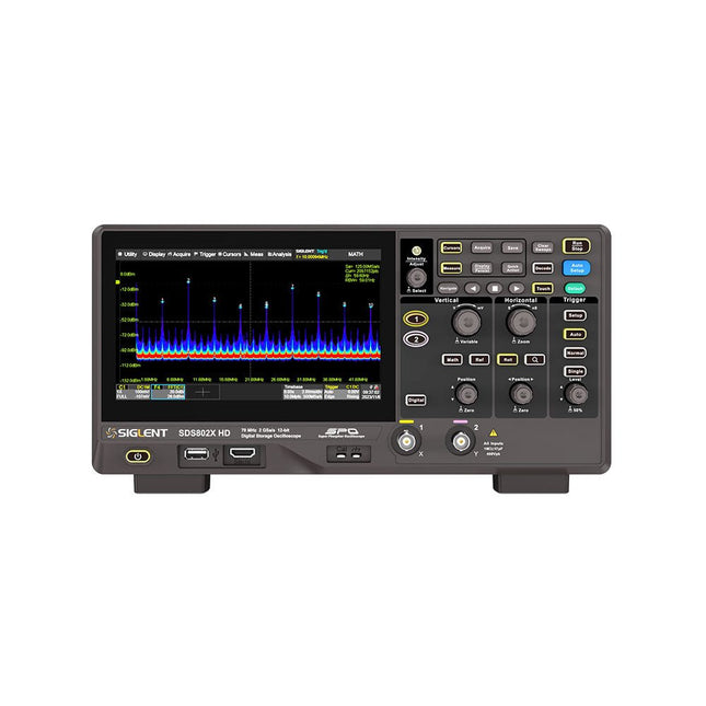
Siglent Siglent SDS822X HD 2-ch Oscilloscope (200 MHz)
The Siglent SDS822X HD digital storage oscilloscope is based on 2 GSa/s, 12-bit Analog-Digital Converters and front ends with excellent noise floor performance. With a 200 MHz bandwidth, and a maximum record length of 100 Mpts, and the capability to analyze 2 analog channels alongside 16 digital channels, the SDS822X HD is perfectly suited for mixed signal analysis. Features 12-bit High Resolution 12-bit Analog-Digital Convertors with sample rate up to 2 GSa/s Front ends with 70 μVrms noise floor @ 200 MHz bandwidth 2/4 analog channels, up to 700 MHz bandwidth SPO technology Waveform capture rate up to 120,000 wfm/s (normal mode), and 500,000 wfm/s (sequence mode) Supports 256-level intensity grading and color temperature display modes. Up to 50 Mpts record length Digital trigger system Intelligent trigger: Edge, Slope, Pulse width, Window, Runt, Interval, Dropout, Pattern, Video (HDTV supported), Qualified, Nth edge, Delay, Setup/Hold time. Serial bus triggering and decoder, supports protocols I²C, SPI, UART, CAN, LIN. Segmented acquisition (Sequence) mode, dividing the maximum record length into multiple segments (up to 80,000), according to trigger conditions set by the user, with a very small dead time between segments to capture the qualifying event. History waveform record (History) function, the maximum recorded waveform length is 80,000 frames. Automatic measurements on 50+ parameters, supports statistics with histogram, track, trend, Gating measurement, and measurements on Math, History and Ref. 4 Math traces (2 Mpts FFT, addition, subtraction, multiplication, division, integration, differential, square root, etc.), supports formula editor. Abundant data analysis functions such as Search, Navigate, Counter, Bode plot and Power Analysis High Speed hardware-based Mask Test function, with Mask Editor tool for creating user-defined masks 16 digital channels (optional) 25 MHz waveform generator (optional) 7" TFT-LCD display with 1024 x 600 resolution; Capacitive touch screen supports multi-touch gestures. Interfaces include: USB Hosts, USB Device (USBTMC), LAN (VXI-11/Telnet/Socket), Pass/Fail, Trigger Out Built-in web server supports remote control over the LAN port using a web browser. Supports SCPI remote control commands. Supports external mouse and keyboard. Supports NTP. Specifications Analog Channels 2 Bandwidth 200 MHz Vertical resolution 12-bit Sample rate (Max.) One channel mode: 100 Mpts/chTwo channel mode: Mpts/chFour channel mode: 25 Mpts/ch Memory depth (Max.) One channel mode: 50 Mpts/chTwo channel mode: 25 Mpts/ch Waveform capture rate (Max.) Normal mode: 120,000 wfm/sSequence mode: 500,000 wfm/s Trigger type Edge, Slope, Pulse width, Window, Runt, Interval, Dropout, Pattern, Video, Qualified, Nth edge, Delay, Setup/Hold time, Serial Serial trigger and decode (Standard) I²C, SPI, UART, CAN, LIN Measurement 50+ parameters, statistics, histogram, trend, and track supported Math 4 traces 2 Mpts FFT, Filter, +, -, x, ÷, ∫dt, d/dt, √, Identity, Negation, Absolute, Sign, ex, 10x, ln, lg, Interpolation, MaxHold, MinHold, ERES, Average. Supports formula editor Data analysis Search, Navigate, History, Mask Test, Counter, Bode plot, and Power Analysis Digital channel (optional) 16-channel; maximum sample rate up to 1 GSa/s; record length up to 10 Mpts USB AWG module (option) One channel, 25 MHz, sample rate of 125 MHz, wave length of 16 kpts, isolated output I/O 2x USB 2.0 Host, USB 2.0 Device, 10/100 M LAN, Auxiliary output (TRIG OUT, PASS/FAIL), SBUS (Siglent MSO) Probe (Standard) Passive probe PB470 for each channel Display 7 TFT-LCD with capacitive touch screen (1024x600) Included 1x Siglent SDS822X Oscilloscope 2x Passive probe (200 MHz) PP520 1x Power cord (EU) 1x USB cable 1x Certificate of calibration 1x Quick start Downloads Datasheet Manual Programming guide
€ 635,25
-

Siglent Siglent SSA3032X Plus Spectrum Analyzer (9 kHz – 3.2 GHz)
The Siglent SSA3032X Plus spectrum analyzer is a powerful and flexible tool for RF signal and network analysis. With a frequency range of 3.2 GHz, the analyzer delivers reliable automatic measurements and multiple modes of operation: spectrum analyzer the base, optional functions include RF power measurement, vector signal modulation analysis, reflection measurement, and EMI test. Applications include broadcast monitoring/evaluation, site surveying, S-parameter measurement, analog/digital modulation analysis, EMI pre-compliance test, research and development, education, production, and maintenance. Features Spectrum Analyzer Frequency Range from 9 kHz to 3.2 GHz –161 dBm/Hz Displayed Average Noise Level (Typ.) –98 dBc/Hz. @ 10 kHz Offset Phase Noise (1 GHz, Typ.) Level Measurement Uncertainty <0.7 dB (Typ.) 1 Hz Minimum Resolution Bandwidth (RBW) Preamplifier (Std.) Tracking Generator (incl. free of charge) Analog and Digital Signal Modulation Analysis Mode (opt.) Reflection Measurement Kit (opt.) EMI Filter and Quasi-Peak Detector Kit (opt.) Advanced Measurement Kit (opt.) 10.1-inch Multi-Touch Screen , Mouse and Keyboard supported Web Browser Remote Control on PC and Mobile Terminals and File Operation Specifications SSA3015X Plus SSA3021X Plus SSA3032X Plus SSA3075X Plus Frequency Range 9 kHz ~ 1.5 GHz 9 kHz ~ 2.1 GHz 9 kHz ~ 3.2 GHz 9 kHz ~ 7.5 GHz Resolution Bandwidth 1 Hz ~ 1 MHz 1 Hz ~ 1 MHz 1 Hz ~ 1 MHz 1 Hz ~ 3 MHz Phase Noise <–99 dBc/Hz <–98 dBc/Hz <–98 dBc/Hz <–98 dBc/Hz Total Amplitude Accuracy <1.2 dB <0.7 dB <0.7 dB <0.7 dB Display Average Noise Level –156 dBm/Hz –161 dBm/Hz –161 dBm/Hz –165 dBm/Hz Included Siglent SSA3032X Plus spectrum analyzer USB cable Power cord Quick start guide Downloads Datasheet Manual Documentation Firmware
€ 2.951,19
-

Siglent Siglent SSA3015X Plus Spectrum Analyzer (9 kHz – 1.5 GHz)
The Siglent SSA3015X Plus spectrum analyzer is a powerful and flexible tool for RF signal and network analysis. With a frequency range of 1.5 GHz, the analyzer delivers reliable automatic measurements and multiple modes of operation: spectrum analyzer the base, optional functions include RF power measurement, vector signal modulation analysis, reflection measurement, and EMI test. Applications include broadcast monitoring/evaluation, site surveying, S-parameter measurement, analog/digital modulation analysis, EMI pre-compliance test, research and development, education, production, and maintenance. Features Spectrum Analyzer Frequency Range from 9 kHz to 1.5 GHz –156 dBm/Hz Displayed Average Noise Level (Typ.) –99 dBc/Hz. @ 10 kHz Offset Phase Noise (1 GHz, Typ.) Level Measurement Uncertainty <1.2 dB (Typ.) 1 Hz Minimum Resolution Bandwidth (RBW) Preamplifier (Std.) Tracking Generator (incl. free of charge) Analog and Digital Signal Modulation Analysis Mode (opt.) Reflection Measurement Kit (opt.) EMI Filter and Quasi-Peak Detector Kit (opt.) Advanced Measurement Kit (opt.) 10.1-inch Multi-Touch Screen , Mouse and Keyboard supported Web Browser Remote Control on PC and Mobile Terminals and File Operation Specifications SSA3015X Plus SSA3021X Plus SSA3032X Plus SSA3075X Plus Frequency Range 9 kHz ~ 1.5 GHz 9 kHz ~ 2.1 GHz 9 kHz ~ 3.2 GHz 9 kHz ~ 7.5 GHz Resolution Bandwidth 1 Hz ~ 1 MHz 1 Hz ~ 1 MHz 1 Hz ~ 1 MHz 1 Hz ~ 3 MHz Phase Noise <–99 dBc/Hz <–98 dBc/Hz <–98 dBc/Hz <–98 dBc/Hz Total Amplitude Accuracy <1.2 dB <0.7 dB <0.7 dB <0.7 dB Display Average Noise Level –156 dBm/Hz –161 dBm/Hz –161 dBm/Hz –165 dBm/Hz Included Siglent SSA3015X Plus spectrum analyzer USB cable Power cord Quick start guide Downloads Datasheet Manual Documentation Firmware
€ 1.402,39
-
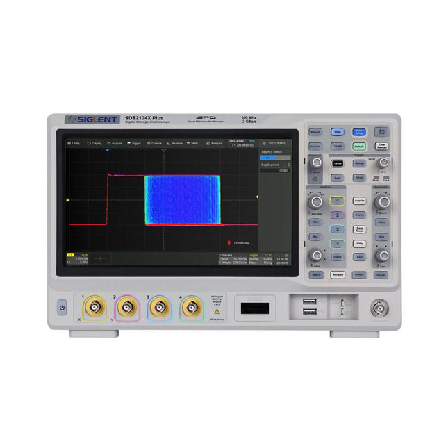
Siglent Siglent SDS2104X Plus 4-ch Oscilloscope (100 MHz)
Siglent's SDS2000X Plus series Digital Storage Oscilloscopes are available in bandwidths of 100 MHz, 200 MHz, and 350 MHz, have a maximum sample rate of 2 GSa/s, a maximum record length of 200 Mpts/ch, and up to 4 analog channels + 16 digital channels mixed-signal analysis ability. The SDS2000X Plus series employs Siglent’s SPO technology with a maximum waveform capture rate of up to 120,000 wfm/s (normal mode, up to 500,000 wfm/s in Sequence mode), 256-level intensity grading display function plus a color temperature display mode. It also employs an innovative digital trigger system with high sensitivity and low jitter. The trigger system supports multiple powerful triggering modes including serial bus triggering. History waveform recording, Sequence acquisition, Search and Navigate functions allow for extended waveform records to be captured, stored, and analyzed. An impressive array of measurement and math capabilities, options for a 50 MHz waveform generator, as well as serial decoding, mask test, bode plot, and power analysis are also features of the SDS2000X Plus. A 10-bit acquisition mode helps to satisfy applications that require more than 8-bit resolution. The large 10.1’’ capacitive touch screen supports multi-touch gestures, while the remote web control, mouse and external keyboard support greatly improve the operating efficiency of the SDS2000X Plus. Features 100 MHz, 200 MHz, 350 MHz (upgradable to 500 MHz) models Real-time sampling rate up to 2 GSa/s Record length up to 200 Mpts Serial bus triggering and decoder, supports I²C, SPI, UART, CAN, LIN, CAN FD, FlexRay, I²S and MIL-STD-1553B Provide 10 bit mode, Vertical and Horizontal Zoom Capacitive touch screen supports multi-touch gestures Siglent SDS2000X Plus Oscilloscopes SDS2102X Plus SDS2104X Plus SDS2204X Plus SDS2354X Plus Bandwidth 100 MHz 100 MHz 200 MHz 350 MHz Channels 2 4 4 4 Real-time sampling rate 2 GSa/s 2 GSa/s 2 GSa/s 2 GSa/s Capture rate 120,000 wfm/s 120,000 wfm/s 120,000 wfm/s 120,000 wfm/s Memory depth 200 Mpts/ch 200 Mpts/ch 200 Mpts/ch 200 Mpts/ch Included Siglent SDS2104X Plus Oscilloscope Passive probes Power cord USB cable Manual Downloads Datasheet Manual Quick guide Manual Firmware
€ 1.160,63
-

Siglent Siglent SDS2102X Plus 2-ch Oscilloscope (100 MHz)
Siglent's SDS2000X Plus series Digital Storage Oscilloscopes are available in bandwidths of 100 MHz, 200 MHz, and 350 MHz, have a maximum sample rate of 2 GSa/s, a maximum record length of 200 Mpts/ch, and up to 4 analog channels + 16 digital channels mixed-signal analysis ability. The SDS2000X Plus series employs Siglent’s SPO technology with a maximum waveform capture rate of up to 120,000 wfm/s (normal mode, up to 500,000 wfm/s in Sequence mode), 256-level intensity grading display function plus a color temperature display mode. It also employs an innovative digital trigger system with high sensitivity and low jitter. The trigger system supports multiple powerful triggering modes including serial bus triggering. History waveform recording, Sequence acquisition, Search and Navigate functions allow for extended waveform records to be captured, stored, and analyzed. An impressive array of measurement and math capabilities, options for a 50 MHz waveform generator, as well as serial decoding, mask test, bode plot, and power analysis are also features of the SDS2000X Plus. A 10-bit acquisition mode helps to satisfy applications that require more than 8-bit resolution. The large 10.1’’ capacitive touch screen supports multi-touch gestures, while the remote web control, mouse and external keyboard support greatly improve the operating efficiency of the SDS2000X Plus. Features 100 MHz, 200 MHz, 350 MHz (upgradable to 500 MHz) models Real-time sampling rate up to 2 GSa/s Record length up to 200 Mpts Serial bus triggering and decoder, supports I²C, SPI, UART, CAN, LIN, CAN FD, FlexRay, I²S and MIL-STD-1553B Provide 10 bit mode, Vertical and Horizontal Zoom Capacitive touch screen supports multi-touch gestures Siglent SDS2000X Plus Oscilloscopes SDS2102X Plus SDS2104X Plus SDS2204X Plus SDS2354X Plus Bandwidth 100 MHz 100 MHz 200 MHz 350 MHz Channels 2 4 4 4 Real-time sampling rate 2 GSa/s 2 GSa/s 2 GSa/s 2 GSa/s Capture rate 120,000 wfm/s 120,000 wfm/s 120,000 wfm/s 120,000 wfm/s Memory depth 200 Mpts/ch 200 Mpts/ch 200 Mpts/ch 200 Mpts/ch Included Siglent SDS2102X Plus Oscilloscope Passive probes Power cord USB cable Manual Downloads Datasheet Manual Quick guide Manual Firmware
€ 855,20
-

€ 65,90€ 42,95
Best Price
-

€ 79,90€ 54,95
Best Price
-
€ 44,90€ 34,95
Best Price
-
€ 79,90€ 44,95
Best Price
-

€ 199,90€ 179,95
Best Price
-

€ 79,90€ 44,95
Best Price
-
€ 92,90€ 69,95
Best Price
-

€ 84,75€ 64,95
Best Price
-

€ 72,60€ 49,80
Best Price
-

€ 154,90€ 104,95
Best Price
-

€ 77,75€ 54,95
Best Price
-

€ 104,75€ 79,95
Best Price
-

€ 102,90€ 79,95
Best Price


