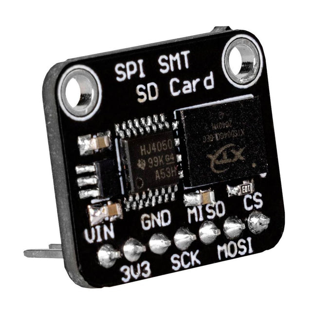
This flash memory allows you to store and read data externally via the SPI interface of your microcontroller. The control of the module is exactly the same as with a conventional SD card and is therefore particularly simple. The module is especially suitable for mobile setups, where normal SD cards could slip out of the SD card slot. Specifications Special feature 3 V and 5 V operation due to the integrated voltage converter Supply voltage Vcc 3-5 V Logic level Vcc Interface SPI Memory size 512 MB Clock frequency Up to 50 MHz Dimensions 18 x 22 x 12 mm Weight 3 g
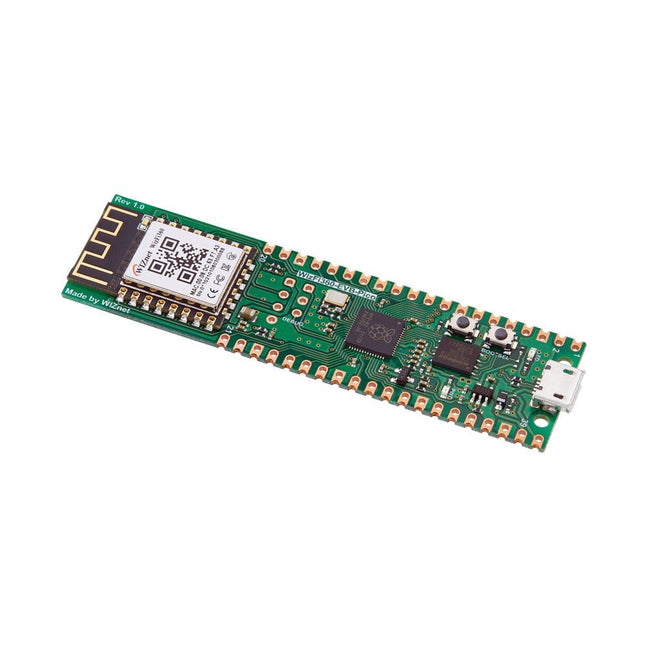
Raspberry Pi Pico EVB combined with the WizFi360-PAWizFi360-EVB-Pico is based on Raspberry Pi RP2040 and adds Wi-Fi connectivity using WizFi360. It is pin-compatible with Raspberry Pi Pico board and can be used for IoT Solution development.Specifications
RP2040 microcontroller with 2 MByte Flash
Dual-core cortex M0+ at up to 133 MHz
264 kByte multi-bank high performance SRAM
External Quad-SPI Flash with eXecute In Place (XIP)
Includes WizFi360-PA
Supports Hardwired Internet Protocols: TCP, UDP, WOL over UDP, ICMP, IGMPv1/v2, IPv4, ARP, PPPoE
WiFi 2.4G, 802.11 b/g/n
Support Station / SoftAP / SoftAP+Station operation modes
Support “Data pass-through” and “AT command data transfer” mode
Support serial AT command configuration
Support TCP Server / TCP Client / UDP operating mode
Support configuration of operating channel 0 ~ 13
Support auto 20 MHz / 40 MHz bandwidth
Support WPA_PSK / WPA2_PSK encryption
Support built-in unique MAC address and user configurable
Industrial grade (operating temperature range: -40°C ~ 85°C)
CE, FCC certification
Includes 16 Mbit Flash Memory
Micro-USB B port for power and data (and for reprogramming the Flash)
40 pin 21×51 ‘DIP’ style 1mm thick PCB with 0.1' through-hole pins also with edge castellations
3-pin ARM Serial Wire Debug (SWD) port
Built-in LDO
DownloadsDocumentation
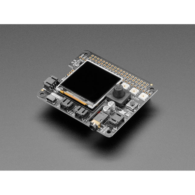
This carrier board combines a 2.4" TFT display, six addressable LEDs, onboard voltage regulator, a 6-pin IO connector, and microSD slot with the M.2 pin connector slot so that it can be used with compatible processor boards in our MicroMod ecosystem. We've also populated this carrier board with Atmel's ATtiny84 with 8kb of programmable flash. This little guy is preprogrammed to communicate with the processor over I²C to read button presses.
Features
M.2 MicroMod Connector
240 x 320 pixel, 2.4" TFT display
6 Addressable APA102 LEDs
Magnetic Buzzer
USB-C Connector
3.3 V 1 A Voltage Regulator
Qwiic Connector
Boot/Reset Buttons
RTC Backup Battery & Charge Circuit
microSD
Phillips #0 M2.5 x 3 mm screw included
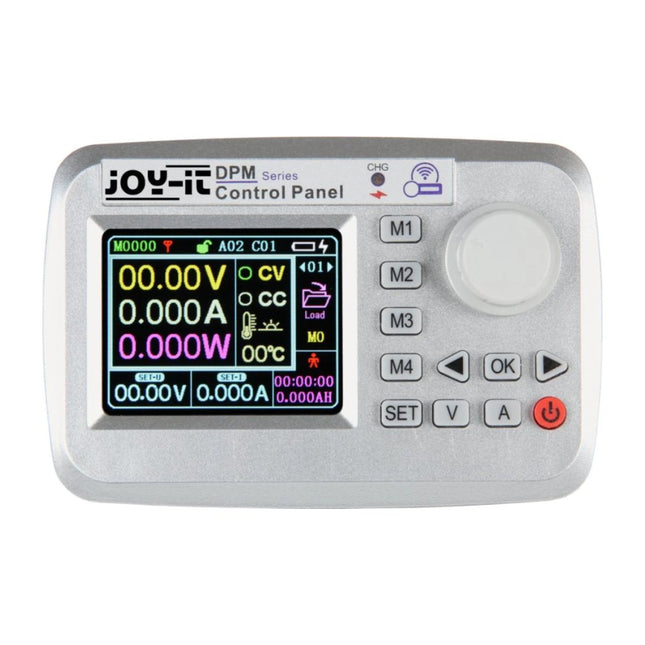
SPECIFICATIONS WIRELESS TRANSMISSION METHOD radiofrequency transmission RANGE up to 10 meters COMMUNICATION ADRESS 0 - 99 COMMUNICATION CHANNEL 0 - 30 BATTERY OF CONTROL PANEL 3.7 V 2000 mAh DISPLAY SIZE 2.4 Inch (6.35cm) DIMENSIONS 120 x 80 x 25mm WEIGHT 108 g ITEMS SHIPPED Control panel, cables
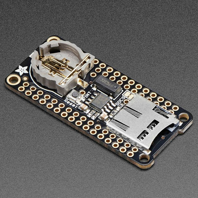
This FeatherWing will make it easy to add data logging to any Feather Board you might have. You get both an I²C real-time clock (PCF8523) with 32 KHz crystal and battery backup, and a microSD socket that connects to the SPI port pins (+ extra pin for CS). Note: FeatherWing doesn't come with a microSD card. A CR1220 coin cell is required to use the RTC battery-backup capabilities. If you're not using the RTC part of the FeatherWing, a battery is not required. To talk to the microSD card socket Arduino's default SD library is recommended. Some light soldering is required to attach the headers onto the Wing. Pinouts Power pins On the bottom row, the 3.3 V (second from left) and GND (fourth from left) pin are used to power the SD card and RTC (to take a load off the coin cell battery when main power is available) RTC & I²C Pins In the top right, SDA (rightmost) and SCL (to the left of SDA) are used to talk to the RTC chip.
SCL - I²C clock pin to connect to your microcontroller's I2C clock line. This pin has a 10 kΩ pull-up resistor to 3.3 V
SDA - I²C data pin to connect to your microcontroller's I2C data line. This pin has a 10 kΩ pull-up resistor to 3.3 V There's also a breakout for INT which is the output pin from the RTC. It can be used as an interrupt output or it could also be used to generate a square wave. Note that this pin is an open drain - you must enable the internal pull-up on whatever digital pin it is connected to. SD & SPI Pins Starting from the left you've got SPI Clock (SCK) - output from feather to wing SPI Master Out Slave In (MOSI) - output from feather to wing SPI Master In Slave Out (MISO) - input from wing to feather These pins are in the same location on every Feather. They are used for communicating with the SD card. When the SD card is not inserted, these pins are completely free. MISO is tri-stated whenever the SD CS (chip select) pin is pulled high
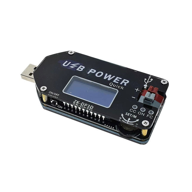
The ZK-DP3D CNC USB-C DC-DC Converter is a versatile, high-precision voltage and current regulator designed for a wide range of applications. Featuring a digital control interface with adjustable voltage (1-30 V) and current (0-2 A), it offers a precision LCD display for monitoring input/output voltage, current, power, and more.
Equipped with intelligent fast-charge protocol support (QC2.0/3.0, FCP, SCP, AFC) and multiple safety protections, it is ideal for powering devices such as USB fans, routers, and batteries. Its compact design includes push-type terminals for easy connectivity and a high power output of up to 15 W, ensuring reliability and convenience for both hobbyists and professionals.
Specifications
Input voltage
4-13 V (3 input interfaces: USB, MicroUSB and USB-C)
Output voltage
1-30 V
Output current
0-2 A
Output power
Less than 15 W
Voltage display
Resolution 0.01 V, Accuracy ±(0.5% + 3 digits)
Current display
Resolution 0.001 A, Range 0-2 A, Accuracy ±(0.5% + 3 digits)
Power display
0.00-15.00 W
Operating current
approx. 30 mA
Dimensions
92 x 40 x 16 mm
Weight
41 g
USB-C to LoRa Dongle is a powerful and versatile LoRa device that lets you connect beyond boundaries. With its exceptional range and easy connectivity, it allows you to seamlessly communicate with devices up to 5 km away. LoRa Dongle is the perfect solution for anyone looking to establish long-range wireless communication in a variety of applications.
This dongle provides direct USB interface control, eliminating the need for a deep understanding of LoRa transmission concepts. They seamlessly connect with devices like Raspberry Pi, SBCs, PCs, and laptops, simplifying the creation of IoT LoRa gateways. The USB LoRa Dongles function as transmitters and receivers, accommodating various message formats, including text, hexadecimal, and decimal.
Features
Device with the most recent LoRa module, offering up to a 5-kilometer data transmission range and higher speeds.
Use new generation LoRa spread spectrum to ensure stable communication
Type C interface for LoRa configuration/Power
Status LED for power and data transmission
Serial TX/RX pin breakout in Header and Screw terminal form
Onboard jumper for operating mode selection
Specifications
Carrier Frequency (License Free ISM): 868 MHz
Chip: Based on SX1262 RF chip
Range: 5Km
Transmitting Power: 22 dBm
Receiving Sensitivity: -147 dbm
Data Rate: Up to 62.5 kbps
Interface: Type C
Communication Port: UART serial
Supply Voltage: 5 V
Operating Voltage: 3.3 V
Operating Temperature: -20 to 70°C
Included
1x USB-C to LoRa Dongle
1x Antenna (868 MHz)
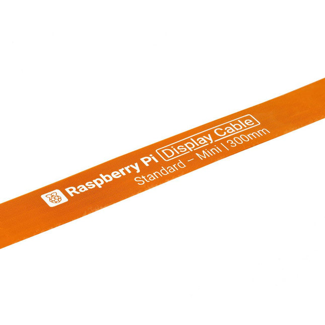
Raspberry Pi 5 provides two four-lane MIPI connectors, each of which can support either a camera or a display. These connectors use the same 22-way, 0.5 mm-pitch “mini” FPC format as the Compute Module Development Kit, and require adapter cables to connect to the 15-way, 1 mm-pitch “standard” format connectors on current Raspbery Pi camera and display products.These mini-to-standard adapter cables for cameras and displays (note that a camera cable should not be used with a display, and vice versa) are available in 200 mm, 300 mm and 500 mm lengths.
ESP32-S3-EYE is a small-sized AI development board. It is based on the ESP32-S3 SoC and ESP-WHO, Espressif’s AI development framework. The ESP32-S3-EYE board consists of two parts: the main board (ESP32-S3-EYE-MB) features the ESP32-S3-WROOM-1 module, a 2-Megapixel camera, a SD card slot, a digital microphone, a USB port, and function buttons; and the sub board (ESP32-S3-EYE-SUB) integrates an LCD display. The main board and sub board are connected through pin headers. ESP32-S3-EYE offers plenty of storage, with an 8 MB Octal PSRAM and a 8 MB flash. It also supports image transmission via Wi-Fi and debugging through a Micro-USB port. Specifications Camera The 2 MP camera OV2640 has a 66.5° field of view and a maximum resolution of 1600x1200. You can change the resolution when developing applications. Module Power LED The LED (green) turns on when USB power is connected to the board. If it is not turned on, it indicates either the USB power is not supplied, or the 5 V to 3.3 V LDO is broken. Software can configure GPIO3 to set different LED statuses (turned on/off, flashing) for different statuses of the board. Note: GPIO3 must be set up in open-drain mode. Pulling GPIO3 up may burn the LED. Pin Headers Connect the female headers on the sub board. 5 V to 3.3 V LDO Power regulator that converts a 5 V supply into a 3.3 V output for the module. Digital Microphone The digital I²S MEMS microphone features 61 dB SNR and –26 dBFS sensitivity, working at 3.3 V. FPC Connector Connects the main board and the sub board. Function Button There are six function buttons on the board. Users can configure any functions as needed except for the RST button. ESP32-S3-WROOM-1 The ESP32-S3-WROOM-1 module embeds the ESP32-S3R8 chip variant that provides Wi-Fi and Bluetooth 5 (LE) connectivity, as well as dedicated vector instructions for accelerating neural network computing and signal processing. On top of the integrated 8 MB Octal SPI PSRAM offered by the SoC, the module also comes with 8 MB flash, allowing for fast data access. ESP32-S3-WROOM-1U module is also supported. MicroSD Card Slot Used for inserting a MicroSD card to expand memory capacity. 3.3 V to 1.5 V LDO Power regulator that converts a 3.3 V supply into a 1.5 V output for the camera. 3.3 V to 2.8 V LDO Power regulator that converts a 3.3 V supply into a 2.8 V output for the camera. USB Port A Micro-USB port used for 5 V power supply to the board, as well as for communication with the chip via GPIO19 and GPIO20. Battery Soldering Points Used for soldering a battery socket to connect an external Li-ion battery that can serve as an alternative power supply to the board. If you use an external battery, make sure it has built-in protection circuit and fuse. The recommended specifications of the battery: capacity > 1000 mAh, output voltage 3.7 V, input voltage 4.2 V – 5 V. Battery Charger Chip 1 A linear Li-ion battery charger (ME4054BM5G-N) in ThinSOT package. The power source for charging is the USB Port. Battery Red LED When the USB power is connected to the board and a battery is not connected, the red LED blinks. If a battery is connected and being charged, the red LED turns on. When the battery is fully charged, it turns off. Accelerometer Three-axis accelerometer (QMA7981) for screen rotation, etc.
Features
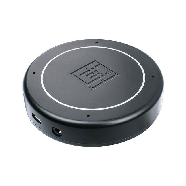
Plug & Play (No driver required), compatible with Windows 10/8/7, Mac, Linux and Android that support OTG.
Voice Pick-up device, Far-field voice pick-up up to 5m and supports 360° pick-up pattern
Acoustic algorithms implemented:
DOA(Direction of Arrival),
AEC(Automatic Echo Cancellation),
AGC(Automatic Gain Control),
NS(Noise Suppression)
Built-in audio jack, which allows for plugging in headphones or speakers (speaker not included)
Applications
Voice pick-up device
Home/Office automation device
In-car voice assistant
Healthcare device
Voice interaction robot
Other applications
Specifications
XVF-3000 from XMOS
4 High-Performance Digital Microphones
Supports Far-field Voice Capture
Speech Algorithms On-Chip
12 Programmable RGB LED Indicators
Microphones: MEMS MSM261D4030H1CPM
Sensitivity: -26 dBFS (Omnidirectional)
Acoustic Overload Point: 120 dB SPL
SNR: 63 dB
Power Supply: 5V DC from Micro USB or Expansion Header
Dimensions: 77mm (Diameter)
3.5mm Audio Jack Output Socket
The Raspberry Pi A+ Case has been designed to fit both the Pi 3 Model A+ and the Pi 1 Model A+. The high-quality ABS construction consists of two parts. The base features cut-outs to allow access to the microSD Card and the the HDMI, audio/video and USB ports, as well as the power connector.
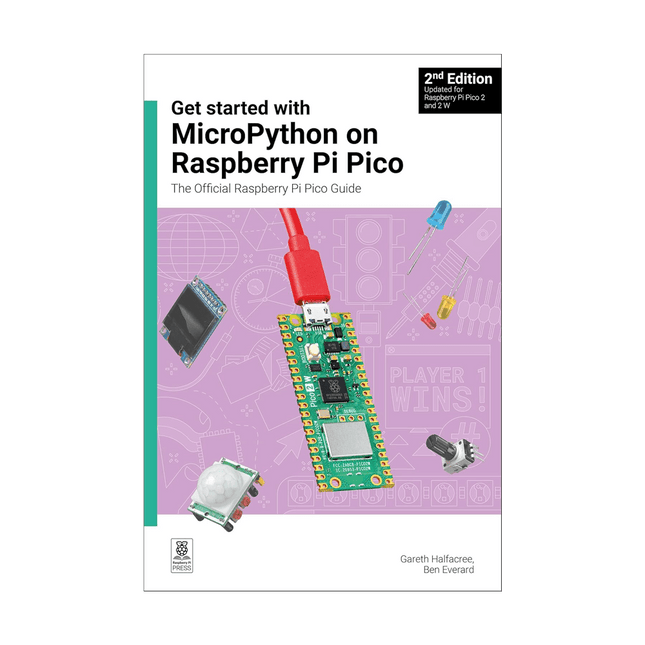
Fully updated for Raspberry Pi Pico W, this book gets you started with Raspberry Pi Pico – whether you’re using Raspberry Pi Pico for a home project, industrial automation, or learning (or teaching!) electronics and programming.
Microcontrollers, like the RP2040 chip at the heart of Raspberry Pi Pico, are computers stripped back to their bare essentials. You don’t use monitors or keyboards with them – instead, you program them over USB to take their input from (and send their output to) on-board input/output pins.
Using these programmable connections, you can light LEDs, make noises, send text to screens, and much more. In this book, you will learn how to use the beginner-friendly MicroPython language to write programs, and you’ll connect up hardware to make your Raspberry Pi Pico interact with the world around it. Using these skills, you can create your own electromechanical projects, whether for fun or to make your life easier.
Fully updated for Raspberry Pi Pico W and the latest version of MicroPython, this book shows you how to:
Get started with Raspberry Pi Pico and Pico W
Work with various electronic components
Create your own programmable electronic contraptions
Turn Raspberry Pi Pico W into a network-connected node for the Internet of Things
Link your Pico W to your smartphone, tablet, or another Pico W with Bluetooth Low Energy (BLE)
Whether you’re using Raspberry Pi Pico for a home project, industrial automation, or learning (or teaching!) electronics and programming, this book will show you how.
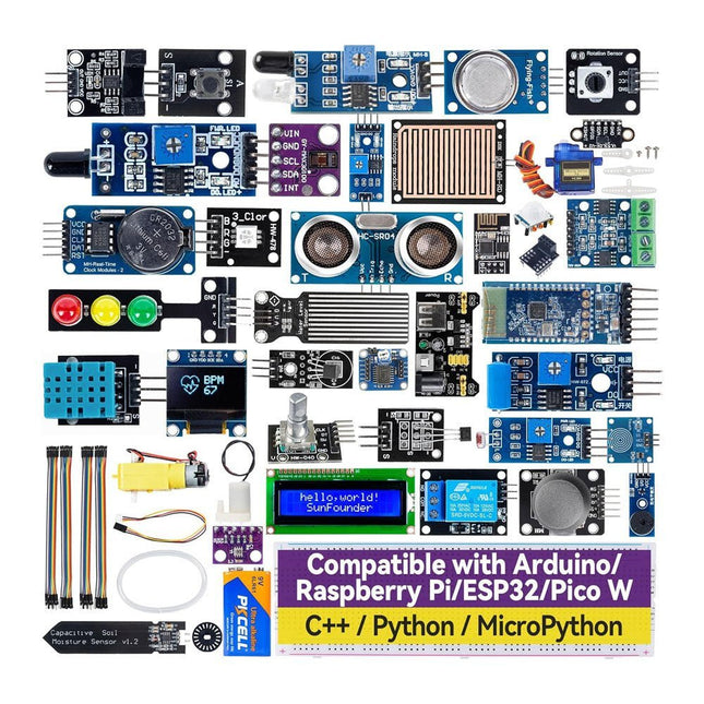
Discover endless creativity with the Universal Maker Sensor Kit, designed for use with Raspberry Pi, Pico W, Arduino, and ESP32. This versatile kit offers compatibility across popular development platforms, including Arduino Uno R4 Minima/WiFi, Uno R3, Mega 2560, Raspberry Pi 5, 4, 3B+, 3B, Zero, Pico W, and ESP32.
Featuring over 35 sensors, actuators, and displays, it's perfect for projects ranging from environmental monitoring and smart home automation to robotics and interactive gaming. Step-by-step tutorials in C/C++, Python, and MicroPython guide beginners and experienced makers alike through 169 exciting projects.
Features
Wide Compatibility: Fully supports Arduino (Uno R3, Uno R4 Minima/WiFi, Mega 2560), Raspberry Pi (5, 4, 3B+, 3B, Zero, Pico W), and ESP32, enabling extensive flexibility across numerous development platforms. Includes instructions for building 169 projects.
Comprehensive Components: Features more than 35 sensors, actuators, and display modules suitable for diverse projects such as environmental monitoring, smart home automation, robotics, and interactive game controllers.
Detailed Tutorials: Provides clear, step-by-step tutorials covering Arduino, Raspberry Pi, Pico W, ESP32, and each included component. Tutorials are available in C/C++, Python, and MicroPython, catering effectively to both beginners and experienced makers.
Suitable for All Skill Levels: Offers structured projects designed to guide users seamlessly from beginner to advanced proficiency in electronics and programming, enhancing creativity and technical expertise.
Included
Breadboard
Button Module
Capacitive Soil Moisture Module
Flame Sensor Module
Gas/Smoke Sensor Module (MQ2)
Gyroscope & Accelerometer Module (MPU6050)
Hall Sensor Module
Infrared Speed Sensor Module
IR Obstacle Avoidance Sensor Module
Joystick Module
PCF8591 ADC DAC Converter Module
Photoresistor Module
PIR Motion Module (HC-SR501)
Potentiometer Module
Pulse Oximeter and Heart Rate Sensor Module (MAX30102)
Raindrop Detection Module
Real Time Clock Module (DS1302)
Rotary Encoder Module
Temperature Sensor Module (DS18B20)
Temperature and Humidity Sensor Module (DHT11)
Temperature, Humidity & Pressure Sensor (BMP280)
Time of Flight Micro-LIDAR Distance Sensor (VL53L0X)
Touch Sensor Module
Ultrasonic Sensor Module (HC-SR04)
Vibration Sensor Module (SW-420)
Water Level Sensor Module
I²C LCD 1602
OLED Display Module (SSD1306)
RGB LED Module
Traffic Light Module
5 V Relay Module
Centrifugal Pump
L9110 Motor Driver Module
Passive Buzzer Module
Servo Motor (SG90)
TT Motor
ESP8266 Module
JDY-31 Bluetooth Module
Power Supply Module
Documentation
Online Tutorial
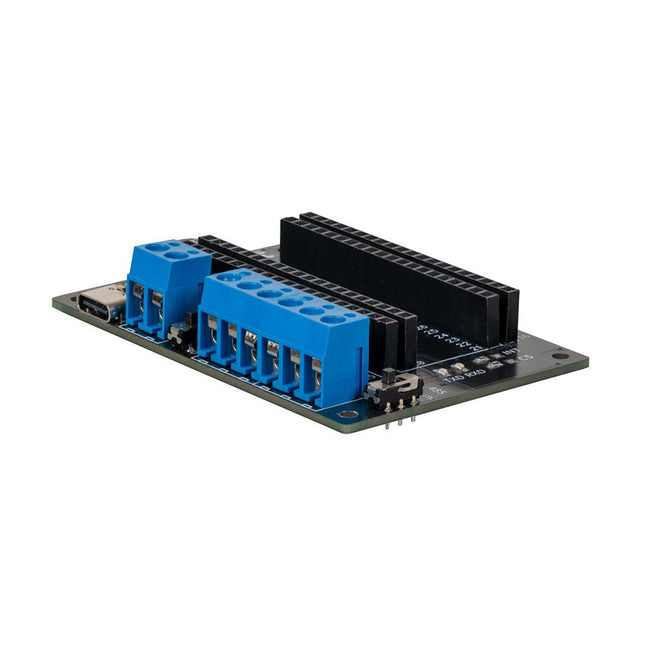
This expansion board allows you to add an RS485 and a CAN interface to a Raspberry Pi Pico.
The board also offers the option of operating it either via a standard USB-C connection with 5 V or via a screw terminal that accepts a voltage of 6 to 12 V. The voltage applied to the screw terminal is reduced to 5 V by a voltage converter integrated on the board.
Features
Power can be supplied via a USB-C connection with 5 V or via a screw terminal that draws between 6 and 12 V. In the latter case, a built-in voltage converter reduces the voltage to 5 V.
To increase the versatility and range of functions, the connection pins of the Raspberry Pi Pico have been routed to the outside.
The expansion board also offers the option of communication via the RS485 and CAN interfaces.
Specifications
CAN Interface
SPI, CAN
RS485 Interface
Serial, RS485
Power supply
5 V DC (USB-C)
Screw terminal
6-12 V DC
Logic level
3.3 V
Terminating resistor CAN
120 Ω (can be activated and deactivated as required)
Terminating resistor RS485
120 Ω (can be activated and deactivated as required)
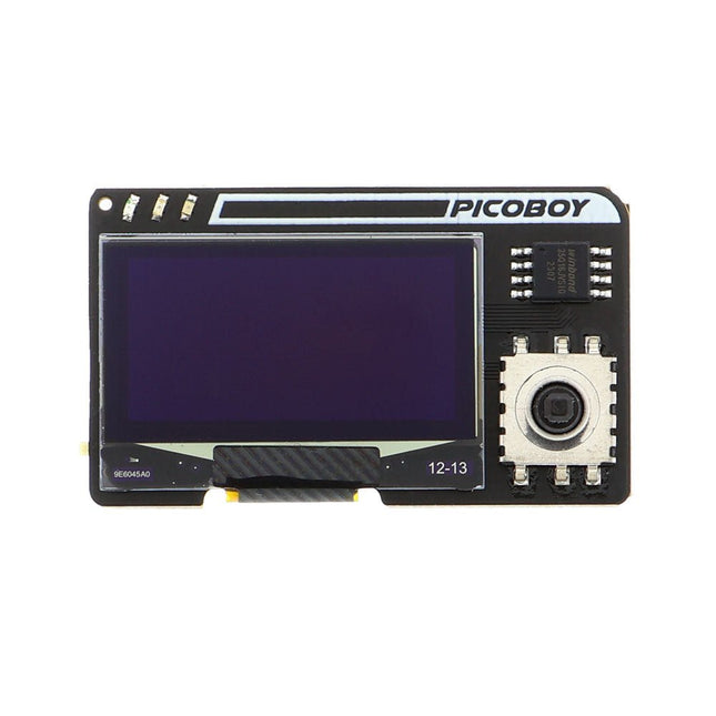
The Picoboy is a powerful mini handheld measuring just 3 x 5 cm. It is suitable for learning programming, developing your own games or simply playing with it. An introduction to programming with the Arduino IDE and MicroPython is available. All you need is a PC, the PicoBoy and a USB-C cable. As the PicoBoy is compatible with the Raspberry Pi Pico and the Arduino IDE, there are countless other tutorials, examples and libraries on the internet to make programming easier. Specifications 1.3' OLED display with 128 x 64 pixels (black/white) RP2040 microcontroller makes it compatible with the Raspberry Pi Pico 2x 133 MHz ARM M0+ 2 MB Flash 264 KB RAM USB-C interface for programming and data transfer 3 Pre-installed games 5-way joystick Acceleration sensor (can now also be used in Python!) Power supply via USB-C or a CR2032 button cell Dimensions: 49,2 x 29,1 x 14,5 mm Downloads GitHub
The iCEBreaker FPGA board is an open-source educational FPGA development board.
The iCEBreaker is great for classes and workshops teaching the use of the open source FPGA design flow through Yosys, nextpnr, IceStorm, Icarus Verilog, Amaranth HDL and others. This means the board is low cost and has a nice set of features to allow for the design of interesting classes and workshop exercises. At the same time it allows the user to use the proprietary vendor tools if they choose to.
After the workshop the boards can be easily used as a development board as most GPIO are exposed, broken out and configurable through jumpers on the back of the board. There is only a minimal amount of buttons and LED that can't be disconnected and used for your own purposes.
Documentation
Workshop
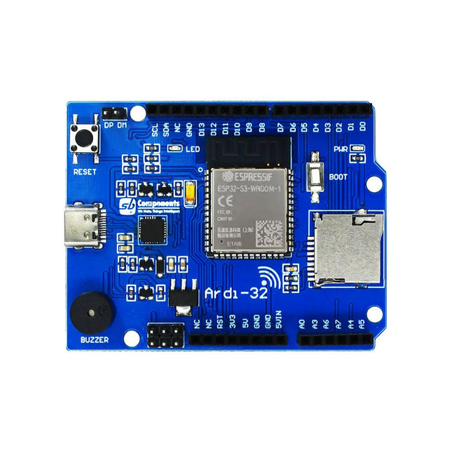
Ardi32 is the ultimate Arduino Uno alternative packed with powerful specs and exciting features in the Arduino Uno form factor. Ardi32 is powered by the latest ESP32-S3-WROOM-1. The built-in Wi-Fi and Bluetooth connectivity makes the board ideal for IoT projects or projects requiring wireless communication.
Features
Powered by powerful ESP32-S3-WROOM-1 module with inbuild WiFi and BLE support.
Arduino Uno form factor, so you can connect 3.3 V compatible Arduino shields
SD card slot for storage and data transfer
The facility of USB-C interface for programming and to the power board
Boot and Reset buttons are available to operate in various modes.
Multifunction GPIO breakout supporting general I/O, UART, I²C, SPI, ADC & PWM functions.
Multi-tune Buzzer to add audio alert into the project
Multi-platform support like Arduino IDE, Espressif IDF, and MicroPython/CircuitPython
Comes with HID support, so the device can simulate a mouse or keyboard
Specifications
ESP32-S3 series of SoCs having Xtensa dual-core 32-bit LX7 microprocessor
4 GHz Wi-Fi (802.11 b/g/n) and Bluetooth 5 (LE)
Flash up to 16 MB, PSRAM up to 8 MB
Board supply 5 V and GPIO pins operating voltage 3.3 V
22 multipurpose GPIOs breakout in Arduino style for easy peripheral and shield interfacing
I²C, SPI, and UART communications protocol support
Cross-platform development and multiple programming language support
Features
Synchronous mode: Auto, Normal, Single, None, Scan
Rising/Falling edge trigger
Modes of vertical precise, horizontal precise measurement and triggering threshold
Auto Measurement: frequency, cycle time, duty cycle, DC RMS voltage/Vpp /Vmax/Vmin/Vavg
Inbuilt signal generator/10 Hz-1 MHz square wave (duty adjustable) or 10 Hz-20 KHz
Sine/Square/Triangle/Sawtooth wave
Specifications
Analog bandwidth
1 MHz
Max sample rate
10 Msa/s
Max sample memory depth
8K
Analog input impedance
1 MΩ
Max input voltage
±40 V (X1)
Coupling
AC/DC
Vertical sensitivity
20 mv/Div~10 V/Div (1-2-5)
Horizontal sensitivity
1 uS/Div~2 S/Div (1-2-5)
Storage
Built-in 8 MB U disk storage for waveform data and images
Power supply
Internal 550 mAh Lithium battery, recharging through Micro USB port
Display
2.8' Full Color TFT LCD (320x240 pixels)
Dimensions
100 x 56.5 x 10.7 mm
Downloads
User Manual
Source Code
App
Learn about data-driven farming using AI, Machine learning and IoT with free curated curriculums and lessons from Microsoft. Students can immerse themselves with hands-on activities and build a garden monitoring system with this kit.
Features
Easy-to-use and low-cost hardware kit: combines an affordable hardware kit with FREE curriculums and activities for students’ hands-on experience in precision agriculture techniques to food production.
New tools for STEAM Education learners: students learn about AI, Machine learning, and IoT by building a garden monitoring system.
Easily use with Raspberry Pi 4: with atmospheric and environmental sensors to understand their soil's health, analyze data, and make decisions.
Real-time data collection: The student-built IoT devices connect to custom Microsoft Excel workbooks that collect real-time data using Excel’s Data Streamer.
Building your own Machine Learning models: using Lobe.ai, students apply the technique to predict nutrient deficiencies in their plants and identifying pests in their garden.
Introducing Microsoft responsible AI framework: engaging students with some of the social and ethical challenges raised by this new technology.
Applications
Combined with software and curriculum & resources, you can get hands-on experience, learn about artificial intelligence, machine learning, the Internet of Things, data science and then apply the knowledge in growing plants in the real world.
This kit is highly suitable for use in different scenarios, no matter in the classroom, at home, at maker spaces/ fab labs or through distance learning courses:
School garden monitoring
Home garden monitoring
Distance teaching /learning
Online courses
Hobby and DIY projects
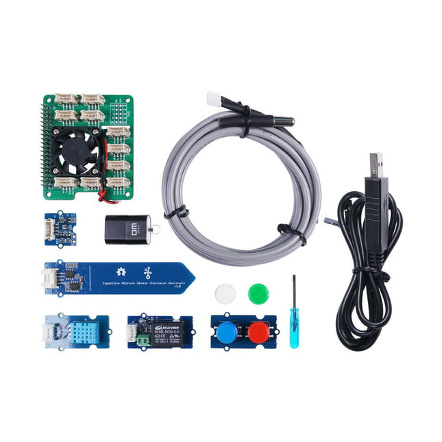
Included
1x Grove Base Hat for Raspberry Pi with a Fan
1x One Wire Temperature Sensor
1x Grove Capacitive Soil Moisture Sensor
1x Grove Sunlight Sensor
1x Grove Temperature & Humidity Sensor
1x Grove Relay
1x Grove Dual Button
1x micro SD Card with Card Reader (32 GB)
1x USB to TTL Serial Cable
1x Screwdriver
Downloads
FarmBeats for Student Kit Brochure
FarmBeats Student Image
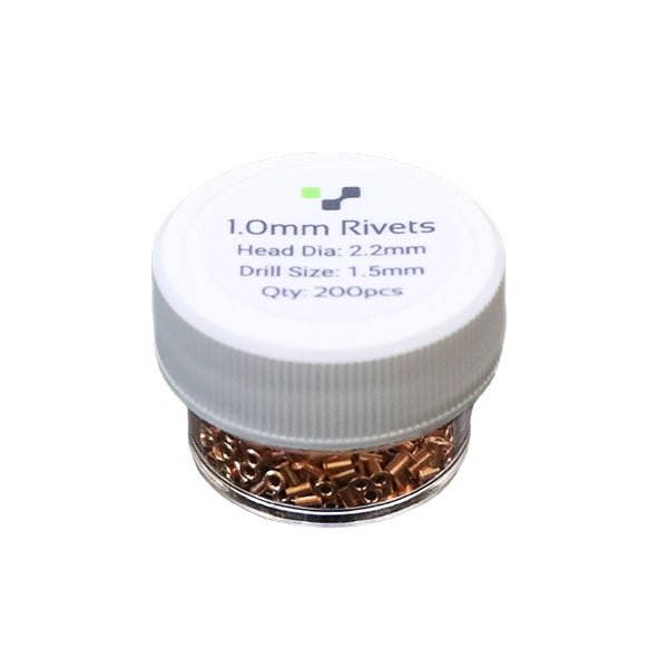
Do you need a way to connect the top and bottom layers? Rivets are the key!Rivets are little copper tubes that make a mechanical connection between the top and bottom layer. We found rivets to be the easiest way to create vias. Be sure to pick up the corresponding rivet tool if you don't have one!
Pack of 200
Inner Diameter - 1.0mm
Head Diameter - 2.2mm
Drill Size: 1.5mm (or 1.6mm)
Confused on how to use them? Checkout our tutorial here.
Features
1.54" IPS TFT display with 240x240 resolution that can show text or video
Stereo speaker ports for audio playback - either text-to-speech, alerts or for creating a voice assistant.
Stereo headphone out for audio playback through a stereo system, headphones, or powered speakers.
Stereo microphone input - perfect for making your very own smart home assistants
Two 3-pin JST STEMMA connectors that can be used to connect more buttons, a relay, or even some NeoPixels!
STEMMA QT plug-and-play I2C port can be used with any of Adafruits 50+ I2C STEMMA QT boards or can be used to connect to Grove I²C devices with an adapter cable.
5-Way Joystick + Button for user interface and control.
Three RGB DotStar LEDs for colorful LED feedback.
The STEMMA QT port means you can attach heat image sensors like the Panasonic Grid-EYE or MLX90640. Heat-Sensitive cameras can be used as a person detector, even in the dark! An external accelerometer can be attached for gesture or vibration sensing such as machinery/industrial predictive maintenance projects
Please note: A Raspberry Pi 4 is not included.
The SparkFun JetBot AI Kit V3.0 is a great launchpad for creating entirely new AI projects for makers, students, and enthusiasts interested in learning AI and building fun applications. It’s straightforward to set up and use and is compatible with many popular accessories.
Several interactive tutorials show you how to harness AI's power to teach the SparkFun JetBot to follow objects, avoid collisions, and more. The Jetson Nano Developer Kit (not included in this kit) offers useful tools like the Jetson GPIO Python library and is compatible with standard sensors and peripherals; including some new python compatibility with the SparkFun Qwiic ecosystem.
Additionally, the included image is delivered with the advanced functionality of JetBot ROS (Robot Operating System) and AWS RoboMaker Ready with AWS IoT Greengrass already installed. SparkFun’s JetBot AI Kit is the only kit currently on the market ready to move beyond the standard JetBot examples and into the world of connected and intelligent robotics.
This kit includes everything you need to get started with JetBot minus a Phillips head screwdriver and an Ubuntu desktop GUI. If you need these, check out the includes tabs for some suggestions from our catalogue. Please be aware that the ability to run multiple neural networks in parallel may only be possible with a full 5V-4A power supply.
Features
SparkFun Qwiic ecosystem for I²C communication
The ecosystem can be expanded using 4x Qwiic connectors on GPIO header
Example Code for Basic Motion, Teleoperation, Collision avoidance, & Object Following
Compact form factor to optimize existing neural net from NVIDIA
136° FOV camera for machine vision
Pre-flashed MicroSD card
Chassis assembly offers expandable architecture
No soldering required
Included
64 GB MicroSD card - pre-flashed SparkFun JetBot image:
Nvidia Jetbot base image with the following installed: SparkFun Qwiic python library package
Driver for Edimax WiFi adapter
Greengrass
Jetbot ROS
Leopard Imaging 136FOV wide-angle camera & ribbon cable
EDIMAX WiFi Adapter
SparkFun Qwiic Motor Driver
SparkFun Micro OLED Breakout (Qwiic)
All hardware & prototyping electronics needed to complete your fully functional robot!
Required
NVIDIA Jetson Nano Developer Kit
Downloads
Assembly Guide