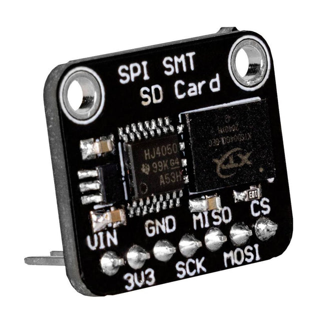
This flash memory allows you to store and read data externally via the SPI interface of your microcontroller.
The control of the module is exactly the same as with a conventional SD card and is therefore particularly simple.
The module is especially suitable for mobile setups, where normal SD cards could slip out of the SD card slot.
Specifications
Special feature
3 V and 5 V operation due to the integrated voltage converter
Supply voltage Vcc
3-5 V
Logic level
Vcc
Interface
SPI
Memory size
512 MB
Clock frequency
Up to 50 MHz
Dimensions
18 x 22 x 12 mm
Weight
3 g
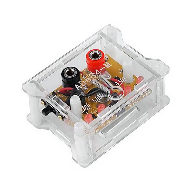
The AD584 4-ch Voltage Reference Module is designed to provide stable and accurate reference voltages of 2.5 V, 5 V, 7.5 V, and 10 V. It incorporates the AD584 integrated circuit, known for its high accuracy and stability.
Features
Multiple Output Voltages: The module can output four different reference voltages (2.5 V, 5 V, 7.5 V, and 10 V) accessible through a single port.
Microcontroller-based Switching: An onboard microcontroller facilitates switching between the four voltage outputs, with LED indicators displaying the active selection.
User-Friendly Operation: A single button allows for easy cycling through the available reference voltages.
Transparent Housing: The module is encased in a transparent housing, offering protection while allowing users to view the internal components.
Power Supply Options: It can be powered via a built-in lithium battery (not included) or through a 5 V DC input. A charging indicator provides status updates during charging.
Output Interface: Equipped with 4mm banana sockets for secure and reliable connections.
Included
1x AD584 4-ch Voltage Reference Module with Housing
Downloads
Datasheet
The Raspberry Pi A+ Case has been designed to fit both the Pi 3 Model A+ and the Pi 1 Model A+. The high-quality ABS construction consists of two parts. The base features cut-outs to allow access to the microSD Card and the the HDMI, audio/video and USB ports, as well as the power connector.
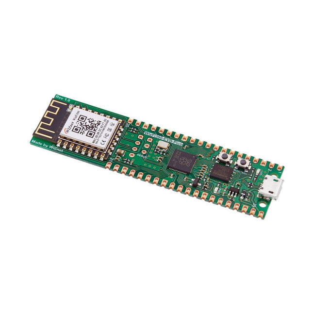
Raspberry Pi Pico EVB combined with the WizFi360-PAWizFi360-EVB-Pico is based on Raspberry Pi RP2040 and adds Wi-Fi connectivity using WizFi360. It is pin-compatible with Raspberry Pi Pico board and can be used for IoT Solution development.Specifications
RP2040 microcontroller with 2 MByte Flash
Dual-core cortex M0+ at up to 133 MHz
264 kByte multi-bank high performance SRAM
External Quad-SPI Flash with eXecute In Place (XIP)
Includes WizFi360-PA
Supports Hardwired Internet Protocols: TCP, UDP, WOL over UDP, ICMP, IGMPv1/v2, IPv4, ARP, PPPoE
WiFi 2.4G, 802.11 b/g/n
Support Station / SoftAP / SoftAP+Station operation modes
Support “Data pass-through” and “AT command data transfer” mode
Support serial AT command configuration
Support TCP Server / TCP Client / UDP operating mode
Support configuration of operating channel 0 ~ 13
Support auto 20 MHz / 40 MHz bandwidth
Support WPA_PSK / WPA2_PSK encryption
Support built-in unique MAC address and user configurable
Industrial grade (operating temperature range: -40°C ~ 85°C)
CE, FCC certification
Includes 16 Mbit Flash Memory
Micro-USB B port for power and data (and for reprogramming the Flash)
40 pin 21×51 ‘DIP’ style 1mm thick PCB with 0.1' through-hole pins also with edge castellations
3-pin ARM Serial Wire Debug (SWD) port
Built-in LDO
DownloadsDocumentation
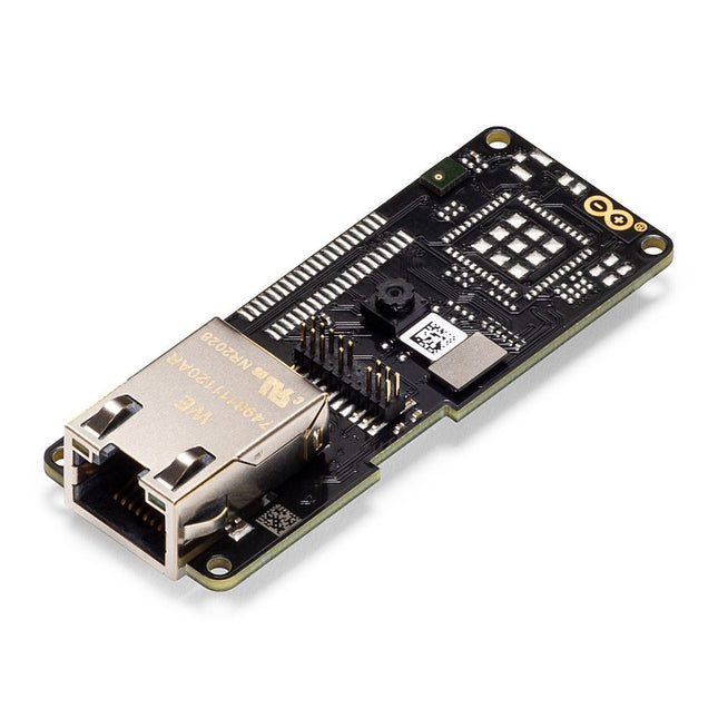
W6100-EVB-Pico is a microcontroller evaluation board based on the Raspberry Pi RP2040 and fully hardwired TCP/IP controller W6100 – and basically works the same as Raspberry Pi Pico board but with additional Ethernet via W6100. Features RP2040 microcontroller with 2 MByte Flash Dual-core cortex M0+ at up to 133 MHz 264 kByte multi-bank high performance SRAM External Quad-SPI Flash with eXecute In Place (XIP) High performance full-crossbar bus fabric 30 multi-function General Purpose I/O (4 can be used for ADC) 1.8-3.3 V I/O voltage (Note: Pico I/O voltage is fixed at 3.3 V) 12-bit 500 ksps Analogue to Digital Converter (ADC) Various digital peripherals 2x UART, 2x I²C, 2x SPI, 16x PWM channels 1x Timer with 4 alarms, 1x Real Time Counter 2x Programmable IO (PIO) blocks, 8 state machines total Flexible, user-programmable high-speed I/O Can emulate interfaces such as SD card and VGA Includes W6100 Supports Hardwired Internet Protocols: TCP, UDP, IPv6, IPv4, ICMPv6, ICMPv4, IGMP, MLDv1, ARP, PPPoE Supports 8 independent SOCKETs simultaneously with 32 KB memory Internal 16 Kbytes Memory for TX/RX Buffers SPI Interface Micro-USB B port for power and data (and for reprogramming the Flash) 40-pin 21x51 ‘DIP’ style 1 mm thick PCB with 0.1' through-hole pins also with edge castellations 3-pin ARM Serial Wire Debug (SWD) port 10 / 100 Ethernet PHY embedded Supports Auto Negotiation Full / Half Duplex 10 / 100 Based Built-in RJ45 (RB1-125BAG1A) Built-in LDO (LM8805SF5-33V) Downloads Documents Getting started on GitHub Firmware
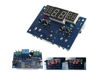
The Intelligent Digital Thermostat Temperature Controller is a small switch controller (77x51mm) which allows you to create your own thermostat. With its NTC Sensor and its LED displays, you are able to switch up to 10A 220V depending on the measured temperature.
This carrier board combines a 2.4" TFT display, six addressable LEDs, onboard voltage regulator, a 6-pin IO connector, and microSD slot with the M.2 pin connector slot so that it can be used with compatible processor boards in our MicroMod ecosystem. We've also populated this carrier board with Atmel's ATtiny84 with 8kb of programmable flash. This little guy is preprogrammed to communicate with the processor over I²C to read button presses.
Features
M.2 MicroMod Connector
240 x 320 pixel, 2.4" TFT display
6 Addressable APA102 LEDs
Magnetic Buzzer
USB-C Connector
3.3 V 1 A Voltage Regulator
Qwiic Connector
Boot/Reset Buttons
RTC Backup Battery & Charge Circuit
microSD
Phillips #0 M2.5 x 3 mm screw included
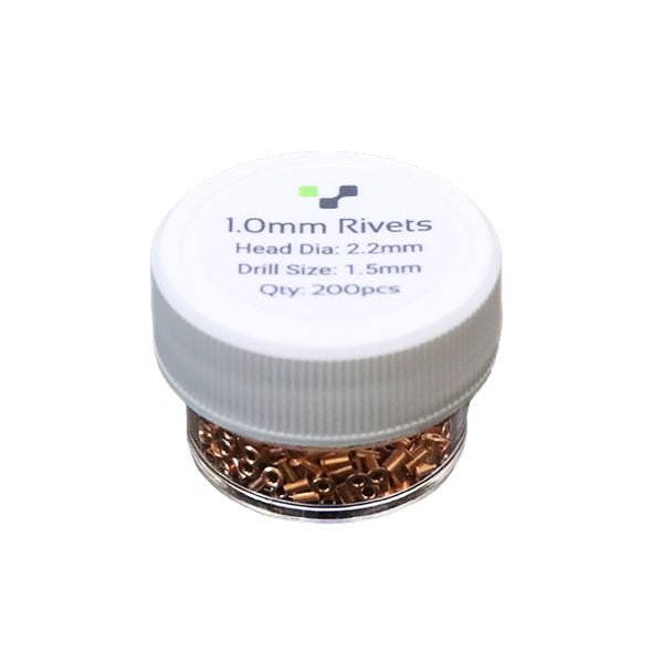
Do you need a way to connect the top and bottom layers? Rivets are the key!
Rivets are little copper tubes that make a mechanical connection between the top and bottom layer. We found rivets to be the easiest way to create vias. Be sure to pick up the corresponding rivet tool if you don't have one!
Pack of 200
Inner Diameter - 1.0mm
Head Diameter - 2.2mm
Drill Size: 1.5mm (or 1.6mm)
Confused on how to use them? Checkout our tutorial here.
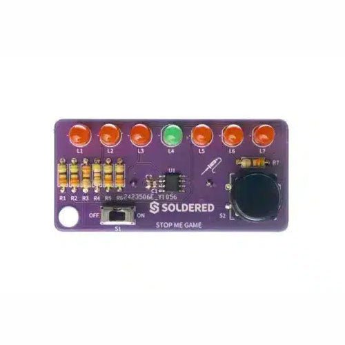
If you are looking for a simple way to learn soldering, or just want to make a small gadget that you can carry, this set is a great opportunity. Stop me game is an educational kit which teaches you how to solder, and in the end, you get to have your own small game. The LEDs go up and down, and your goal is to press the button as soon as the green LED turns on. With every correct answer, the game gets a bit harder – the time you have to press the button shortens. How many correct answers can you get?
It’s based on ATtiny404 microcontroller, programmed in Arduino. At its back, you’ll find CR2032 battery which makes the kit portable. There’s keychain holder as well. Soldering process is easy enough based on the mark on the PCB.
Included
1x PCB
1x ATtiny404 microcontroller
7x LEDs
1x Pushbutton
1x Switch
7x Resistors (330 ohm)
1x CR2032 battery holder
1x Battery CR2032
1x Keychain holder
The Sparkfun Qwiic GPIO is an I²C device based around the TCA9534 I/O Expander IC from Texas Instruments. The board adds eight IO pins that you can read and write just like any other digital pin on your controller. The details of the I²C interface have been taken care of in an Arduino library so you can call functions similar to Arduino's pinMode and digitalWrite, allowing you to focus on your creation! The TCA9534's pins are broken out to easy-to-use latch terminals; never screw another wire into place! The terminals are relatively roomy themselves, so feel free to latch multiple wires into a ground or power terminal. With three customizable address jumpers, you can have up to eight Qwiic GPIO boards connected on a single bus allowing upwards of 64 additional GPIO pins! The default I²C is 0x27 and can be changed by adjusting the jumpers on the board's back. Features Eight Configurable GPIO Pins Available I²C Address: 0x27 (Default) Hardware address pins allow up to eight boards on a single bus Input Polarity Inversion Register Control each I/O pin individually or all at once Open-Drain Active-Low Interrupt Output 2x Qwiic Connectors Dimensions: 60.96 x 38.10 mm
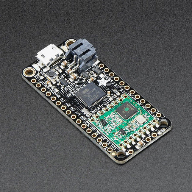
This 900 MHz radio version can be used for either 868 MHz or 915 MHz transmission/reception – the exact radio frequency is determined when you load the software since it can be tuned around dynamically.
At the Feather 32u4's heart is at ATmega32u4 clocked at 8 MHz and at 3.3 V logic. This chip has 32 K of flash and 2 K of RAM, with built in USB so not only does it have a USB-to-Serial program & debug capability built in with no need for an FTDI-like chip, it can also act like a mouse, keyboard, USB MIDI device, etc.
To make it easy to use for portable projects, we added a connector for any 3.7 V Lithium polymer batteries and built in battery charging. You don't need a battery, it will run just fine straight from the micro USB connector. But, if you do have a battery, you can take it on the go, then plug in the USB to recharge. The Feather will automatically switch over to USB power when its available. We also tied the battery thru a divider to an analog pin, so you can measure and monitor the battery voltage to detect when you need a recharge.
Features
Measures 2.0' x 0.9' x 0.28' (51 x 23 x 8 mm) without headers soldered in
Light as a (large?) feather – 5.5 grams
ATmega32u4 @ 8 MHz with 3.3 V logic/power
3.3 V regulator with 500 mA peak current output
USB native support, comes with USB bootloader and serial port debugging
You also get tons of pins – 20 GPIO pins
Hardware Serial, hardware I²C, hardware SPI support
7x PWM pins
10x analog inputs
Built in 100 mA lipoly charger with charging status indicator LED
Pin #13 red LED for general purpose blinking
Power/enable pin
4 mounting holes
Reset button
The Feather 32u4 Radio uses the extra space left over to add an RFM69HCW 868/915 MHz radio module. These radios are not good for transmitting audio or video, but they do work quite well for small data packet transmission when you ned more range than 2.4 GHz (BT, BLE, WiFi, ZigBee)
SX1231 based module with SPI interface
Packet radio with ready-to-go Arduino libraries
Uses the license-free ISM band ('European ISM' @ 868 MHz or 'American ISM' @ 915 MHz)
+13 to +20 dBm up to 100 mW Power Output Capability (power output selectable in software)
50 mA (+13 dBm) to 150 mA (+20 dBm) current draw for transmissions
Range of approx. 350 meters, depending on obstructions, frequency, antenna and power output
Create multipoint networks with individual node addresses
Encrypted packet engine with AES-128
Simple wire antenna or spot for uFL connector
Comes fully assembled and tested, with a USB bootloader that lets you quickly use it with the Arduino IDE. Headrs are also included so you can solder it in and plug into a solderless breadboard. You will need to cut and solder on a small piece of wire (any solid or stranded core is fine) in order to create your antenna.
Lipoly battery and USB cable not included.
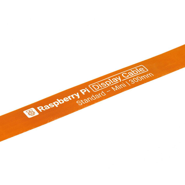
Raspberry Pi 5 provides two four-lane MIPI connectors, each of which can support either a camera or a display. These connectors use the same 22-way, 0.5 mm-pitch “mini” FPC format as the Compute Module Development Kit, and require adapter cables to connect to the 15-way, 1 mm-pitch “standard” format connectors on current Raspbery Pi camera and display products.These mini-to-standard adapter cables for cameras and displays (note that a camera cable should not be used with a display, and vice versa) are available in 200 mm, 300 mm and 500 mm lengths.
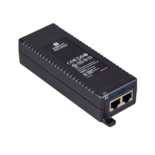
The Raspberry Pi PoE+ Injector adds Power-over-Ethernet (PoE) functionality to a single port of a non-PoE Ethernet switch, delivering both power and data through one Ethernet cable. It provides a plug-and-play, cost-effective solution for incrementally introducing PoE capability into existing Ethernet networks.
The PoE+ Injector is a single-port, 30 W device suitable for powering equipment compliant with IEEE 802.3af and 802.3at standards, including all generations of Raspberry Pi PoE HATs. It supports network pass-through speeds of 10/100/1000 Mbps.
Note: A separate IEC mains cable is required for operation (not included).
Specifications
Data rate
10/100/1000 Mbps
Input voltage
100 to 240 V AC
Output power
30 W
Power output on pins
4/5 (+), 7/8 (–)
Nominal output voltage
55 V DC
Data connectors
Shielded RJ-45, EIA 568A and 568B
Power connector
IEC c13 mains power input (not included)
Storage humidity
Maximum 95%, non-condensing
Operating altitude
–300 m to 3000 m
Operating ambient temperature
10°C to +50°C
Dimensions
159 x 51.8 x 33.5 mm
Downloads
Datasheet
Maker Line is a line sensor with 5 x IR sensors array that is able to track line from 13 mm to 30 mm width.
The sensor calibration is also simplified. There is no need to adjust the potentiometer for each IR sensor. You just have to press the calibrate button for 2 seconds to enter calibration mode. Afterwards you need to sweep the sensors array across the line, press the button again and you are good to go.
The calibration data is saved in EEPROM and it will stay intact even if the sensor has been powered off. Thus, calibration only needs to be carried out once unless the sensor height, line color or background color has changed.
Maker Line also supports dual outputs: 5 x digital outputs for the state of each sensor independently, which is similar to conventional IR sensor, but you get the benefit of easy calibration, and also one analog output, where its voltage represents the line position. Analog output also offers higher resolution compared to individual digital outputs. This is especially useful when high accuracy is required while building a line following robot with PID control.
Features
Operating Voltage: DC 3.3 V and 5 V compatible (with reverse polarity protection)
Recommended Line Width: 13 mm to 30 mm
Selectable line color (light or dark)
Sensing Distance (Height): 4 mm to 40 mm (Vcc = 5 V, Black line on white surface)
Sensor Refresh Rate: 200 Hz
Easy calibration process
Dual Output Types: 5 x digital outputs represent each IR sensor state, 1 x analog output represents line position.
Support wide range of controllers such as Arduino, Raspberry Pi etc.
Downloads
Datasheet
Tutorial: Building A Low-Cost Line Following Robot
The Power Delivery Board uses a standalone controller to negotiate with the power adapters and switch to a higher voltage other than just 5V. This uses the same power adapter for different projects rather than relying on multiple power adapters to provide different output; it can deliver the board as part of SparkFun’s Qwiic connect system, so you won’t have to do any soldering to figure out how things are oriented.
The SparkFun Power Delivery Board takes advantage of the power delivery standard using a standalone controller from STMicroelectronics, the STUSB4500. The STUSB4500 is a USB power delivery controller that addresses sink devices. It implements a proprietary algorithm to negotiate a power delivery contract with a source (i.e. a power delivery wall wart or power adapter) without the need for an external microcontroller. However, you will need a microcontroller to configure the board. PDO profiles are configured in an integrated non-volatile memory. The controller does all the heavy lifting of power negotiation and provides an easy way to configure over I²C.
To configure the board, you will need an I²C bus. The Qwiic system makes it easy to connect the Power Delivery board to a microcontroller. Depending on your application, you can also connect to the I²C bus via the plated through SDA and SCL holes.
Features
Input and output voltage range of 5-20V
Output current up to 5A
Three configurable power delivery profiles
Auto-run Type-C™ and USB PD sink controller
Certified USB Type-C™ rev 1.2 and USB PD rev 2.0 (TID #1000133)
Integrated VBUS voltage monitoring
Integrated VBUS switch gate drivers (PMOS)
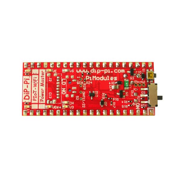
The DiP-Pi Power Master is an Advanced Powering System with embedded sensors interfaces that cover most of possible needs for application based on Raspberry Pi Pico. It can supply the system with up to 1.5 A @ 4.8 V delivered from 6-18 VDC on various powering schemes like Cars, Industrial plant etc., additionally to original micro-USB of the Raspberry Pi Pico. It supports LiPo or Li-Ion Battery with Automatic Charger as also automatic switching from cable powering to battery powering or reverse (UPS functionality) when cable powering lost. Extended Powering Source (EPR) is protected with PPTC Resettable fuse, Reverse Polarity, as also ESD.
The DiP-Pi Power Master contains Raspberry Pi Pico embedded RESET button as also ON/OFF Slide Switch that is acting on all powering sources (USB, EPR or Battery). User can monitor (via Raspberry Pi Pico A/D pins) battery level and EPR Level with PICO’s A/D converters. Both A/D inputs are bridged with 0402 resistors (0 OHM) therefore if for any reason user needs to use those Pico pins for their own application can be easy removed. The charger is automatically charging connected battery (if used) but in addition user can switch charger ON/OFF if their application needs it. DiP-Pi Power Master can be used for cable powered systems, but also for pure Battery Powered System with ON/OFF. Each powering source status is indicated by separate informative LEDs (VBUS, VSYS, VEPR, CHGR, V3V3).
User can use any capacity of LiPo or Li-Ion type; however, must take care to use PCB protected batteries with max discharge current allowed of 2 A. The embedded battery charger is set to charge battery with 240 mA current. This current is set by resistor so if user need more/less can himself to change it.
In Addition to all above features DiP-Pi Power Master is equipped with embedded 1-wire and DHT11/22 sensors interfaces. Combination of the extended powering, battery, and sensors interfaces make the DiP-Pi Power Master ideal for applications like data logger, plants monitoring, refrigerators monitoring etc.
DiP-Pi Power Master is supported with plenty of ready to use examples written in Micro Python or C/C++.
Specifications
General
Dimensions 21 x 51 mm
Raspberry Pi Pico pinout compatible
Independent Informative LEDs (VBUS, VSYS, VEPR, CHGR, V3V3)
Raspberry Pi Pico RESET Button
ON/OFF Slide Switch acting on all powering sources (USB, EPR, Battery)
External Powering 6-18 V DC (Cars, Industrial Applications etc.)
External Power (6-18 VDC) Level Monitoring
Battery Level Monitoring
Inverse Polarity Protection
PPTC Fuse Protection
ESD Protection
Automatic Battery Charger (for PCB protected LiPo, Li-Ion – 2 A Max) Automatic/User Control
Automatic Switch from Cable Powering to Battery Powering and reverse (UPS Functionality)
Various powering schemes can be used at the same time with USB Powering, External Powering and Battery Powering
1.5 A @ 4.8 V Buck Converter on EPR
Embedded 3.3 V @ 600mA LDO
Embedded 1-wire Interface
Embedded DHT-11/22 Interface
Powering Options
Raspberry Pi Pico micro-USB (via VBUS)
External Powering 6-18 V (via dedicated Socket – 3.4/1.3 mm)
External Battery
Supported Battery Types
LiPo with protection PCB max current 2A
Li-Ion with protection PCB max current 2A
Embedded Peripherals and Interfaces
Embedded 1-wire interface
Embedded DHT-11/22 Interface
Programmer Interface
Standard Raspberry Pi Pico C/C++
Standard Raspberry Pi Pico Micro Python
Case Compatibility
DiP-Pi Plexi-Cut Case
System Monitoring
Battery Level via Raspberry Pi Pico ADC0 (GP26)
EPR Level via Raspberry Pi Pico ADC1 (GP27)
Informative LEDs
VB (VUSB)
VS (VSYS)
VE (VEPR)
CH (VCHR)
V3 (V3V3)
System Protection
Direct Raspberry Pi Pico Hardware Reset Button
ESD Protection on EPR
Reverse Polarity Protection on EPR
PPTC 500 mA @ 18 V fuse on EPR
EPR/LDO Over Temperature protection
EPR/LDO Over Current protection
System Design
Designed and Simulated with PDA Analyzer with one of the most advanced CAD/CAM Tools – Altium Designer
Industrial Originated
PCB Construction
2 ozcopper PCB manufactured for proper high current supply and cooling
6 mils track/6 mils gap technology 2 layers PCB
PCB Surface Finishing – Immersion Gold
Multi-layer Copper Thermal Pipes for increased System Thermal Response and better passive cooling
Downloads
Datasheet
Datasheet
Plug a reader into the headers, use a Qwiic cable, scan your 125kHz ID tag, and the unique 32-bit ID will be shown on the screen. The unit comes with a read LED and buzzer, but don't worry, there is a jumper you can cut to disable the buzzer if you want. Utilizing SparkFun's handy Qwiic system, no soldering is required to connect it to the rest of your system. However, we still have broken out 0.1"-spaced pins if you prefer to use a breadboard.
Utilizing the onboard ATtiny84A, the Qwiic RFID takes the six byte ID tag of your 125kHz RFID card, attaches a timestamp to it, and puts it onto a stack that holds up to 20 unique RFID scans at a time. This information is easy to get at with some simple I²C commands.
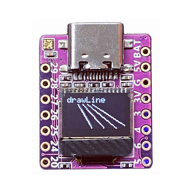
Arduino, MicroPython, and CircuitPython-compatible compact development board powered by Raspberry Pi RP2040
RP2040-0.42LCD is a high-performance development board with integrated 0.42" LCD (70x40 resolution) with flexible digital interfaces.
It incorporates Raspberry Pi's RP2040 microcontroller chip. The RP2040 features a dual-core Arm Cortex-M0+ processor clocked at 133 MHz with 264 KB internal SRAM and 2 MB flash storage.
Specifications
SoC
Raspberry Pi RP2040 dual-core Cortex-M0+ microcontroller at up to 125 MHz, with 264 KB SRAM
Storage
2 MB SPI flash
Display
0.42-inch OLED
USB
1x USB Type-C port for power and programming
Expansion
– Qwiic I²C connector– 7-pin and 8-pin headers with up to 11x GPIOs, 2x SPI, 2x I²C, 4x ADC, 1x UART, 5 V, 3.3 V, VBAT, GND
Misc
– Reset and Boot buttons– RGB LED, power LED
Power supply
– 5 V via USB-C port or Vin– VBAT pin for battery input– 3.3 V regulator with 500 mA peak output
Dimensions
23.5 x 18 mm
Weight
2.5 g
Downloads
GitHub
The EC200U-EU C4-P01 development board features the EC200U-EU LTE Cat 1 wireless communication module, offering a maximum data rate of up to 10 Mbps for downlink and 5 Mbps for uplink. It supports multi-mode and multi-band communication, making it a cost-effective solution.
The board is designed in a compact and unified form factor, compatible with the Quectel multi-mode LTE Standard EC20-CE. It includes an onboard USB-C port, allowing for easy development with just a USB-C cable.
Additionally, the board is equipped with a 40-pin GPIO header that is compatible with most Raspberry Pi HATs.
Features
Equipped with EC200U-EU LTE Cat 1 wireless communication module, multi-mode & multi-band support
Onboard 40-Pin GPIO header, compatible with most Raspberry Pi HATs
5 LEDs for indicating module operating status
Supports TCP, UDP, PPP, NITZ, PING, FILE, MQTT, NTP, HTTP, HTTPS, SSL, FTP, FTPS, CMUX, MMS protocols, etc.
Supports GNSS positioning (GPS, GLONASS, BDS, Galileo, QZSS)
Onboard Nano SIM card slot and eSIM card slot, dual card single standby
Onboard MIPI connector for connecting MIPI screen and is fully compatible with Raspberry Pi peripherals
Onboard camera connector, supports customized SPI cameras with a maximum of 300,000 pixels
Provides tools such as QPYcom, Thonny IDE plugin, and VSCode plugin, etc. for easy learning and development
Comes with online development resources and manual (example in QuecPython)
Specifications
Applicable Regions
Europe, Middle East, Africa, Australia, New Zealand, Brazil
LTE-FDD
B1, B3, B5, B7, B8, B20, B28
LTE-TDD
B38, B40, B41
GSM / GPRS / EDGE
GSM: B2, B3, B5, B8
GNSS
GPS, GLONASS, BDS, Galileo, QZSS
Bluetooth
Bluetooth 4.2 (BR/EDR)
Wi-Fi Scan
2.4 GHz 11b (Rx)
CAT 1
LTE-FDD: DL 10 Mbps; UL 5 Mbps
LTE-TDD: DL 8.96 Mbps; UL 3.1 Mbps
GSM / GPRS / EDGE
GSM: DL 85.6 Kbps; UL 85.6 Kbps
USB-C Port
Supports AT commands testing, GNSS positioning, firmware upgrading, etc.
Communication Protocol
TCP, UDP, PPP, NITZ, PING, FILE, MQTT, NTP, HTTP, HTTPS, SSL, FTP, FTPS, CMUX, MMS
SIM Card
Nano SIM and eSIM, dual card single standby
Indicator
P01: Module Pin 1, default as EC200A-XX PWM0
P05: Module Pin 5, NET_MODE indicator
SCK1: SIM1 detection indicator, lights up when SIM1 card is inserted
SCK2: SIM2 detection indicator, lights up when SIM2 card is inserted
PWR: Power indicator
Buttons
PWK: Power ON/OFF
RST: Reset
BOOT: Forcing into firmware burning mode
USB ON/OFF: USB power consumption detection switch
Antenna Connectors
LTE main antenna + DIV / WiFi (scanning only) / Bluetooth antenna + GNSS antenna
Operating Temperature
−30~+75°C
Storage Temperature
−45~+90°C
Downloads
Wiki
Quectel Resources
The Arduino Pro Portenta Vision Shield brings industry-rated features to your Portenta. This hardware add-on will let you run embedded computer vision applications, connect wirelessly or via Ethernet to the Arduino Cloud or your own infrastructure, and activate your system upon the detection of sound events.
Features
324x324 pixels camera sensor: use one of the cores in Portenta to run image recognition algorithms using the OpenMV for Arduino editor
100 Mbps Ethernet connector: get your Portenta H7 connected to the wired Internet
2 onboard microphones for directional sound detection: capture and analyse sound in real-time
JTAG connector: perform low-level debugging of your Portenta board or special firmware updates using an external programmer
SD-Card connector: store your captured data in the card, or read configuration files
The Vision Shield has been designed to fit on top of the Arduino Portenta family. The Portenta boards feature multicore 32-bit ARM Cortex processors running at hundreds of megahertz, with megabytes of program memory and RAM. Portenta boards come with WiFi and Bluetooth.
Embedded Computer Vision Made Easy
Arduino has teamed up with OpenMV to offer you a free license to the OpenMV IDE, an easy way into computer vision using MicroPython as a programming paradigm. Download the OpenMV for Arduino Editor from our professional tutorials site and browse through the examples we have prepared for you inside the OpenMV IDE. Companies across the whole world are already building their commercial products based on this simple-yet-powerful approach to detect, filter, and classify images, QR codes, and others.
Debugging With Professional Tools
Connect your Portenta H7 to a professional debugger through the JTAG connector. Use professional software tools like the ones from Lauterbach or Segger on top of your board to debug your code step by step. The Vision Shield exposes the required pins for you to plug in your external JTAG.
Camera
Himax HM-01B0 camera module
Resolution
320 x 320 active pixel resolution with support for QVGA
Image sensor
High sensitivity 3.6μ BrightSense pixel technology
Microphone
2 x MP34DT05
Length
66 mm
Width
25 mm
Weight
11 gr
For more information, check out the tutorials provided by Arduino here.
After power on, YDLIDAR G4 start rotating and scanning the environment around it. The scanning distance is 16 m and the device offers a scanning rate of 9,000 times per second.
It makes detailed examinations of its environment and can locate the smallest of objects surrounding it. Featuring a high-precision brushless motor and encoder disc mounted on bearings, it rotates smoothly and has a service life of up to 500,000 hours of operation.
The G4 is an inexpensive solution for projects that require obstacle detection, obstacle avoidance, and/or simultaneous localization and mapping (SLAM). All YDLIDAR products are ROS ready.
Features
360 degree 2D range scanning
Stable performance, high precision
16 m range
Strong resistance to environmental light interference
Brushless motor drive, stable performance
FDA Laser safety standard Class I
360 degree omnidirectional scanning, 5-12 Hz adaptive scanning frequency
OptoMagnetic technology
Wireless data communication
Scanning rate of 9000 Hz
Downloads
Datasheet
User Manual
Development Manual
SDK
Tool
ROS