Features Grove Compatible 3.5mm Connector 6 Disposable Surface Electrodes Power supply voltage: 3.3V-5V 1000mm Cable Leads No additional power supply Specifications Dimensions: 140 mm x 100 mm x 30 mm Weight: 45 g Battery: Exclude Part List 1 x Grove - EMG Detector 1 x Grove Cable 6 x One-off electrode 1 x DC jacket to button connector cable 1000mm
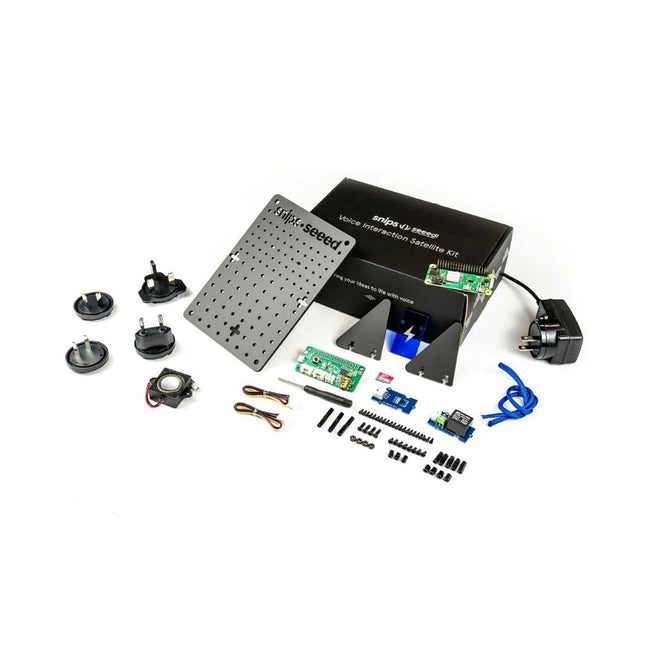
The Voice Interaction Satellite Kit can extend the reach of your base station to each room in your house and enable you to interact with the hardware based on where you issue your commands! You can arrange multiple Satellite Kits throughout your home to add new functionality to Base kit or any other smart speaker, extending your voice control across several rooms.
The Voice Interaction Satellite Kit is powered by a Raspberry Pi Zero W and the ReSpeaker 2-Mics Pi HAT. Along with the kit comes a speaker, a Grove - Temperature Humidity Sensor (SHT31) sensor, a Grove Relay, and a pegboard to hang it on a wall or create a nifty stand.
Note
All Satellite Kits require a Base kit or Raspberry Pi in order to operate as intended.
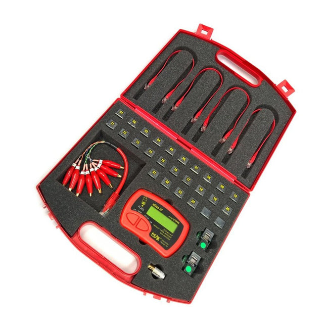
Peak UTP05E is a comprehensive CAT 5/5e/6 network cable analyzer with superb accessories. Easy to use and very fast. Automatically identifies cable type (Straight through, cross-over, token ring etc) and verifies all the connections. Faults are clearly displayed and explained on screen. The Atlas IT will even instruct you on making up standard and special cables, complete with wire colors. Display type is alphanumeric LCD (not backlit).
Features
Automatic connection pattern recognition.
Rapid assessment of all 8 wires within your cable.
Identifies missing connections, shorted connections or incorrect connections.
Will display the identity number of the 'identified' terminators to allow for easy testing and identification of multiple cable runs.
Can display common cable colour codes to help you make up cables.
Included
UTP05 instrument.
2 miniature terminators to plug into another end of the cable run.
4 short patch cables to enable testing of patch panels and wall sockets.
24 miniature identified terminators, great for testing and identifying multiple cable runs.
Pair of RJ11-to-RJ45 adapters to allow for easy testing of RJ11 based cabling.
RJ45 to 8 x gold plated crocodile adapter for testing unterminated cables.
Detailed printed user guide, complete with full-colour Ethernet wiring chart for common cable configurations.
Alkaline battery installed and a spare alkaline battery.
All supplied in a durable padded carry case.
Specifications
Category
Cat 5, 5e, 6 (UTP)
Connection type
RJ45 plug or socket (RJ11 using supplied adapter set)
Lines tested
8 lines (shielding not tested)
Max. cable length
150 metres (500 feet)
Test voltage
±5 V
Test current
±2.5 mA
Temperature range
10°C to 50°C (50°F to 122°F)
Battery operating range
7 V to 13 V
Battery type
GP23, L1128, MN21, V23 (12 V Alkaline)
Instrument dimensions
103 x 70 x 20 mm (4.1 x 2.8 x 0.8")
Terminator dimensions
18 x 15 x 14 mm (0.7 x 0.6 x 0.6")
Downloads
Datasheet
User Guide
Common Ethernet Wiring Diagrams
Avoid socket damage
The FRDM-MCXN947 is a compact and versatile development board designed for rapid prototyping with MCX N94 and N54 microcontrollers. It features industry-standard headers for easy access to the MCU's I/Os, integrated open-standard serial interfaces, external flash memory, and an onboard MCU-Link debugger.
Specifications
Microcontroller
MCX-N947 Dual Arm Cortex-M33 cores @ 150 MHz each with optimized performance efficiency, up to 2 MB dual-bank flash with optional full ECC RAM, External flash
Accelerators: Neural Processing Unit, PowerQuad, Smart DMA, etc.
Memory Expansion
*DNP Micro SD card socket
Connectivity
Ethernet Phy and connector
HS USB-C connectors
SPI/I²C/UART connector (PMOD/mikroBUS, DNP)
WiFi connector (PMOD/mikroBUS, DNP)
CAN-FD transceiver
Debug
On-board MCU-Link debugger with CMSIS-DAP
JTAG/SWD connector
Sensor
P3T1755 I³C/I²C Temp Sensor, Touch Pad
Expansion Options
Arduino Header (with FRDM expansion rows)
FRDM Header
FlexIO/LCD Header
SmartDMA/Camera Header
Pmod *DNP
mikroBUS
User Interface
RGB user LED, plus Reset, ISP, Wakeup buttons
Included
1x FRDM-MCXN947 Development Board
1x USB-C Cable
1x Quick Start Guide
Downloads
Datasheet
Block diagram
With this comprehensive complete set, you can now enter the fascinating world of electronics. In addition to an Oxocard Connect and a breadboard cartridge, it contains 96 electronic components with which you can build a variety of electronic circuits.
Features
Free and unlimited access to the nanopy.io editor with a variety of scripts that you can transfer to your Oxocard Connect at the touch of a button.
Electronics course with 15 experiments that show you step by step how to switch LEDs, connect a servo, generate acoustic signals with a piezo and much more.
Oxocard Connect
High quality microcontroller device with TFT screen, glass cover, joystick, USB-C, as well as revolutionary 16-pin cartridge slot.
The Oxocard Connect represents the next generation of small experimental computers. The universal cartridge slot allows ready-made or self-developed boards to be brought to life instantly by simply plugging them in. Each card comes with drivers and demo programs installed and automatically loaded and started when plugged in.
Breadboard Cartridge
With the Breadboard you can quickly plug in your own circuits. A plug-in board with 17 rows is available for this purpose. Connections: two analog inputs, five digital ports, I²C, SPI, GND/V3.3. access to the 5 V power source of the port. Red LEDs are attached to the digital pins. 5 V can also be injected to power the Oxocard Connect without USB.
Included
1x Oxocard Connect
1x Breadboard Cartridge
Electronic components
1x PIR-Sensor (Motion detector)
1x Thermistor 10 kΩ (Temperature sensor)
1x Photoresistor 10 kΩ (Light sensor)
1x Potentiometer
1x Mikroservo SG92R
1x Piezo (Acoustic signals)
3x LED (green, yellow, red)
2x Buttons
9x Resistances
75x Cables (angled) – various colors and lengths
The LuckFox Pico Ultra is a compact single-board computer (SBC) powered by the Rockchip RV1106G3 chipset, designed for AI processing, multimedia, and low-power embedded applications.
It comes equipped with a built-in 1 TOPS NPU, making it ideal for edge AI workloads. With 256 MB RAM, 8 GB onboard eMMC storage, integrated WiFi, and support for the LuckFox PoE module, the board delivers both performance and versatility across a wide range of use cases.
Running Linux, the LuckFox Pico Ultra supports a variety of interfaces – including MIPI CSI, RGB LCD, GPIO, UART, SPI, I²C, and USB – providing a simple and efficient development platform for applications in smart home, industrial control, and IoT.
Specifications
Chip
Rockchip RV1106G3
Processor
Cortex-A7 1.2 GHz
Neural Network Processor (NPU)
1 TOPS, supports int4, int8, int16
Image Processor (ISP)
Max input 5M @30fps
Memory
256 MB DDR3L
WiFi + Bluetooth
2.4GHz WiFi-6 Bluetooth 5.2/BLE
Camera Interface
MIPI CSI 2-lane
DPI Interface
RGB666
PoE Interface
IEEE 802.3af PoE
Speaker interface
MX1.25 mm
USB
USB 2.0 Host/Device
GPIO
30 GPIO pins
Ethernet
10/100M Ethernet controller and embedded PHY
Default Storage Medium
eMMC (8 GB)
Included
1x LuckFox Pico Ultra W
1x LuckFox PoE module
1x IPX 2.4G 2 db antenna
1x USB-A to USB-C cable
1x Screws pack
Downloads
Wiki
The JOY-iT R301T fingerprint sensor module is capable of image collection and algorithm calculation due to this integrated chip. Another remarkable function of the sensor is, that it can recognize the fingerprint in different conditions, for example humidity, light texture or changes of the skin. This offers a very wide range of possible applications to secure locks and doors among others. The chip can send data via UART, TTL serial and USB to the connected controller.
Specifications
Model
JP2000 sensor
Chip
32 Bit ARM Cortex-M3
Chip storage
96 kB RAM, 1 MB Flash
Power supply
4.2-6.0 V
Working current
Typical: 40 mAPeak: 50 mA
Logic level
3,3/5 V TTL Logic
Fingerprint storage capacity
3000 Prints
Matching mode
1:N Identification1:1 Verification
Adjustable security level
1 - 5 levels(default security level: 3)
False acceptance rate
< 0.001%(on security level 3)
False acceptance rate
< 0.1%(on security level 3)
Response time
Pre-treatment: < 0.45 sMatch: < 1.5 s
Baud rate support
9600 - 921600
UART communication
No parity, Stop Bit: 1
Dimensions
42 x 19 x 8 mm
Included
1x Fingerprint sensor COM-FP-R301T
1x Cable
Downloads
Datasheet
Manual
The CubeCell series is designed primarily for LoRa/LoRaWAN node applications.
Built on the ASR605x platform (ASR6501, ASR6502), these chips integrate the PSoC 4000 series MCU (ARM Cortex-M0+ Core) with the SX1262 module. The CubeCell series offers seamless Arduino compatibility, stable LoRaWAN protocol operation, and straightforward connectivity with lithium batteries and solar panels.
The HTCC-AB02S is a developer-friendly board with an integrated AIR530Z GPS module, ideal for quickly testing and validating communication solutions.
Features
Arduino compatible
Based on ASR605x (ASR6501, ASR6502), those chips are already integrated the PSoC 4000 series MCU (ARM Cortex M0+ Core) and SX1262
LoRaWAN 1.0.2 support
Ultra low power design, 21 uA in deep sleep
Onboard SH1.25-2 battery interface, integrated lithium battery management system (charge and discharge management, overcharge protection, battery power detection, USB/battery power automatic switching)
Good impendence matching and long communication distance
Onboard solar energy management system, can directly connect with a 5.5~7 V solar panel
Micro USB interface with complete ESD protection, short circuit protection, RF shielding, and other protection measures
Integrated CP2102 USB to serial port chip, convenient for program downloading, debugging information printing
Onboard 0.96-inch 128x64 dot matrix OLED display, which can be used to display debugging information, battery power, and other information
Using Air530 GPS module with GPS/Beidou Dual-mode position system support
Specifications
Main Chip
ASR6502 (48 MHz ARM Cortex-M0+ MCU)
LoRa Chipset
SX1262
Frequency
863~870 MHz
Max. TX Power
22 ±1 dBm
Max. Receiving Sensitivity
−135 dBm
Hardware Resource
2x UART1x SPI2x I²C1x SWD3x 12-bit ADC input8-channel DMA engine16x GPIO
Memory
128 Kb FLASH16 Kb SRAM
Power consumption
Deep sleep 21 uA
Interfaces
1x Micro USB1x LoRa Antenna (IPEX)2x (15x 2.54 Pin header) + 3x (2x 2.54 Pin header)
Battery
3.7 V lithium battery (power supply and charging)
Solar Energy
VS pin can be connected to 5.5~7 V solar panel
USB to Serial Chip
CP2102
Display
0.96" OLED (128 x 64)
Operating temperature
−20~70°C
Dimensions
55.9 x 27.9 x 9.5 mm
Included
1x CubeCell HTCC-AB02S Development Board
1x Antenna
1x 2x SH1.25 battery connector
Downloads
Datasheet
Schematic
GPS module (Manual)
Quick start
GitHub
The CubeCell series is designed primarily for LoRa/LoRaWAN node applications.
Built on the ASR605x platform (ASR6501, ASR6502), these chips integrate the PSoC 4000 series MCU (ARM Cortex-M0+ Core) with the SX1262 module. The CubeCell series offers seamless Arduino compatibility, stable LoRaWAN protocol operation, and straightforward connectivity with lithium batteries and solar panels.
The HTCC-AB01 (V2) is an upgraded version of the HTCC-AB01 board.
Features
Arduino compatible
Based on ASR605x (ASR6501, ASR6502), those chips are already integrated the PSoC 4000 series MCU (ARM Cortex-M0+ Core) and SX1262
LoRaWAN 1.0.2 support
Ultra low power design, 3.5 uA in deep sleep
Onboard SH1.25-2 battery interface, integrated lithium battery management system (charge and discharge management, overcharge protection, battery power detection, USB/battery power automatic switching)
Good impendence matching and long communication distance. Onboard solar energy management system, can directly connect with a 5.5~7 V solar panel
Micro USB interface with complete ESD protection, short circuit protection, RF shielding, and other protection measures
Integrated CP2102 USB to serial port chip, convenient for program downloading, debugging information printing
Specifications
Main Chip
ASR6502 (48 MHz ARM Cortex-M0+ MCU)
LoRa Chipset
SX1262
Frequency
863~870 MHz
Max. TX Power
21 ±1 dBm
Max. Receiving Sensitivity
−134 dBm
Hardware Resource
1x UART1x SPI1x I²C1x SWD1x 12-bit ADC input8-channel DMA engine8x GPIO2x PWM
Memory
128 Kb FLASH16 Kb SRAM
Power consumption
Deep Sleep 3.5 uA
Interfaces
1x USB-C1x LoRa Antenna (IPEX 1.0)SH1.25; 11x 2x 2.54 Pin header1x (2x 2.54 Pin header)
Solar Energy
VS pin can be connected to 5.5~7 V solar panel
Battery
3.7 V Lithium battery (power supply and charging)
Operating temperature
−20~70°C
Dimensions
40.6 x 22.9 x 7.6 mm
Included
1x CubeCell HTCC-AB01 (V2) Development Board
1x Antenna
1x 2x SH1.25 battery connector
Downloads
Datasheet
Schematic
Quick start
GitHub
The DE-5050 Insulation Tester is a versatile instrument designed for measuring insulation resistance, low resistance, and AC/DC voltage. Its user-friendly features make it suitable for various electrical testing applications.
Features
Offers five selectable test voltages for different test requirements
Automatically detects AC/DC voltage and displays frequency when AC voltage exceeds 10 V
Stores up to 100 sets of test results with date and time
Switches off automatically after 10 minutes of inactivity
Equipped with a backlit display
Enables zero adjustment for low resistance measurements
Automatic calculation and display of the Dielectric Absorption Ratio (DAR) and Polarization Index (PI) during the insulation resistance test
Specifications
Test Voltages
50 V, 100 V/125 V, 250 V, 500 V, 1000 V
Insulation Resistance Range
Up to 20 GΩ at 500 VUp to 40 GΩ at 1000 V
Voltage Measurement Accuracy
±1%rdg±4dgt (sine wave)
Dimensions
160 x 100 x 46 mm
Weight
380 g (excluding batteries)
Downloads
Datasheet
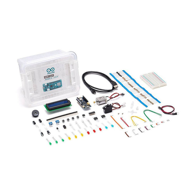
The best way to start exploring the world of connected devices using the Arduino MKR WiFi 1010. The MKR IoT bundle contains all you need to build your first connected devices. Follow the 5 step by step tutorials we have prepared for you and combining the electronic components included in the bundle, you’ll quickly learn how to build devices that connect to the Arduino IoT cloud. All you need to start with IoT This bundle is contains all the hardware and software required to build your first IoT devices with no extra fees. Build 5 IoT projects All the components needed to start your journey into building your own IoT projects. Learn about the Arduino IoT cloud Not only learn about electronic but also about the possibilities the Arduino IoT cloud can offer. Included 1x Arduino MKR1000 WiFi (with mounted headers) 6x Phototransistors 1x Tilt Sensor 1x Temperature sensor (TMP36) 3x Potentiometer 1x Piezo capsule 10x Pushbuttons 1x DC Motor 1x Small servo motor 1x Alphanumeric LCD (16x2 characters) 1x Optocouplers (4N35) 1x H-bridge motor driver (L293D) 2x Mosfet transistors (IRF520) 5x Capacitors 100uF 70x Solid core jumper wires 1x Micro USB cable 1x Breadboard 1x LED (bright white) 3x LEDs (blue) 1x LED (RGB) 8x LED 5 mm (red) 8x LED 5 mm (green) 8x LED 5 mm (yellow) 1x Male pins strip (4x1) 1x Stranded jumper wires (red) 1x Stranded jumper wires (black) 5x Diode 20x 220 Ω resistors 5x 560 Ω resistors 5x 1 KΩ resistors 5x 4.7 KΩ resistors 20x 10 KΩ resistors 5x 1 MΩ resistors 5x 10 MΩ resistors
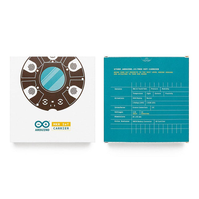
The MKR IoT Carrier comes equipped with 5 RGB LEDs, 5 capacitive touch buttons, a colored display, IMU and a variety of quality sensors. It also features a battery holder for a 18650 Li-Ion battery, SD card holder and Grove connectors.
Data Capture: Map the environment around the carrier using the integrated temperature, humidity, and pressure sensors and collect data about movement using the 6 axis IMU and light, gesture, and proximity sensors. Easily add more external sensors to capture more data from more sources via the on-board Grove connectors (x3).
Data Storage: Capture and store all the data locally on an SD card, or connect to the Arduino IoT Cloud for real-time data capture, storage, and visualization.
Data Visualisation: Locally view real-time sensor readings on the built-in OLED Color Display and create visual or sound prompts using the embedded LEDs and buzzer.
Total Control: Directly control small-voltage electronic appliances using the onboard relays and the five tactile buttons, with the integrated display providing a handy on-device interface for immediate control.
The ATmega328 Uno Development Board (Arduino Uno compatible) is a microcontroller board based on the ATmega328.
It has 14 digital input/output pins (of which 6 can be used as PWM outputs), 6 analogue inputs, a 16 MHz ceramic resonator, a USB connection, a power jack, an ICSP header and a reset button.
It contains everything needed to support the microcontroller; connect it to a computer with a USB cable or power it with a AC-to-DC adapter or battery to get started.
Specifications
Microcontroller
ATmega328
Operating voltage
5 V DC
Input voltage (recommended)
7-12 V DC
Input voltage (limits)
6-20 V DC
Digital I/O pins
14 (of which 6 provide PWM output)
Analogue input pins
6
SRAM
2 kB (ATmega328)
EEPROM
1 kB (ATmega328)
Flash memory
32 kB (ATmega328) of which 0.5 kB used by bootloader
Clock speed
16 MHz
Downloads
Manual
This is a high-performance cooling solution designed to effectively dissipate heat and ensure optimal operating temperatures for the Raspberry Pi. It is an essential accessory for users who want to enhance the performance and longevity of their Raspberry Pi device.
The compact design of the Water cooling kit for Raspberry Pi 5 allows it to be seamlessly installed on the top and bottom of the Raspberry Pi 5, ensuring efficient heat transfer and perfectly protecting the bottom of the Raspberry Pi. Its simple installation process eliminates the need for complex wiring or additional tools, making it friendly to both beginners and experienced Raspberry Pi enthusiasts.
With its powerful cooling performance, the water cooling kit for Raspberry Pi 5 for effectively dissipates heat generated by the Raspberry Pi during intensive tasks or prolonged usage. This helps prevent overheating and ensures stable performance. Efficient water-cooled cooling will allow you to connect multiple Raspberry Pi boards to a set of cooling devices. When using Raspberry Pi in a cluster, you can use a set of water-cooled devices to effectively cool multiple Raspberry Pi boards.
Features
Made for Raspberry Pi: Specially designed for Raspberry Pi 5, 1:1 mold opening, covering all heat sources, including CPU, Wi-Fi, power chip, and eMMC.
Cooling Performance: Effectively dissipates the heat generated by the Raspberry Pi, ensuring optimal operating temperatures and preventing overheating.
Easy to Use: The integrated design of the water pump and cooling fan is convenient for users to install.
RGB Color Lighting: RGB-colored lights are installed at the fan and water pump locations.
Included
1x Water cooling kit
1x Water cooling radiator
1x Black heatsink
2x Silicone hose
1x 12 V/2 A power adapter (US)
4x Hexagonal screw M2.5x10
1x L-key hex wrench
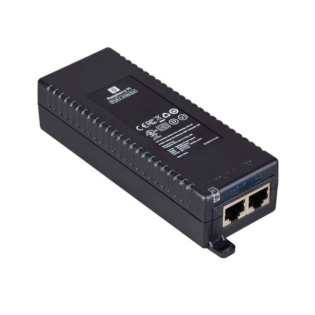
The Raspberry Pi PoE+ Injector adds Power-over-Ethernet (PoE) functionality to a single port of a non-PoE Ethernet switch, delivering both power and data through one Ethernet cable. It provides a plug-and-play, cost-effective solution for incrementally introducing PoE capability into existing Ethernet networks.
The PoE+ Injector is a single-port, 30 W device suitable for powering equipment compliant with IEEE 802.3af and 802.3at standards, including all generations of Raspberry Pi PoE HATs. It supports network pass-through speeds of 10/100/1000 Mbps.
Note: A separate IEC mains cable is required for operation (not included).
Specifications
Data rate
10/100/1000 Mbps
Input voltage
100 to 240 V AC
Output power
30 W
Power output on pins
4/5 (+), 7/8 (–)
Nominal output voltage
55 V DC
Data connectors
Shielded RJ-45, EIA 568A and 568B
Power connector
IEC c13 mains power input (not included)
Storage humidity
Maximum 95%, non-condensing
Operating altitude
–300 m to 3000 m
Operating ambient temperature
10°C to +50°C
Dimensions
159 x 51.8 x 33.5 mm
Downloads
Datasheet
An SMD Magazine rail holds up to eight SMD Magazines. A given rail can be used to hold a project-specific set of magazines indefinitely. Magazines are held at a right angle, ready to be picked and placed by Pixel Pump. Each SMD-Magazine Rail presents up to eight magazines at the perfect angle for you to pick and place their components using Pixel Pump. You can also use these rails to group components for specific projects. They are equipped with non-slip rubber feet and weighted for extra stability.
SMD Magazines are injection-molded containers and a great way to organize and consume SMD parts. They are custom built to store components and present them for picking. They can load up to 12-mm-wide, 9.5-mm tall tapes. They replace those hard-to-find plastic bags while being an excellent source of parts to pick and placing using Pixel Pump. Each SMD-Magazine Rail presents up to eight magazines at the perfect angle for you to pick and place their components using Pixel Pump. You can also use these rails to group components for specific projects. They are equipped with non-slip rubber feet and weighted for extra stability.
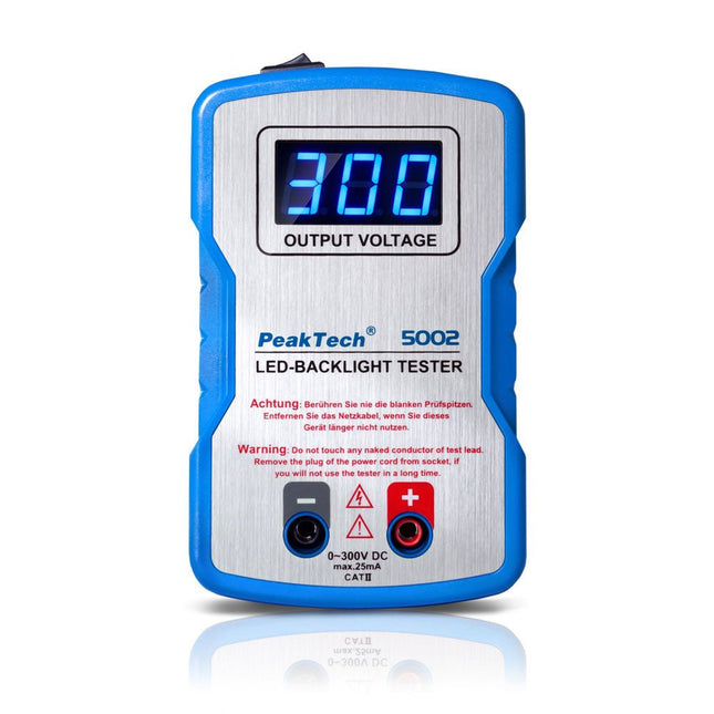
The PeakTech 5002 is a highly practical component tester designed for LEDs and various other electronic components. It delivers an automatically adjustable DC output voltage ranging from 0 to 300 V, adapting to the connected load to prevent damage to sensitive components. This makes it particularly well-suited for use in service and repair workshops.
Features
Output of automatic test voltage from 0 V to 300 V
Suitable for testing individual LEDs or LED panels
Suitable for testing the withstand voltage of electrolytic capacitors
Suitable for Zener voltage testing of Zener diodes
Safety: EN 61010-1
Specifications
Input Voltage
AC 100-240 V (Fuse: 2 A/250 V)
Frequency
50-60 Hz
Power consumption
10 W
Output Voltage
DC 0-300 V
Accuracy
±5% +10 digts.
Output Current
<25 mA
Dimensions
126 x 77 x 36 mm
Weight
141 g
Included
1x PeakTech 5002 LED Tester
2x Test leads
1x Power cable
1x Carrying case
1x Manual
Downloads
Datasheet (English/Deutsch)
Datasheet (Italiano)
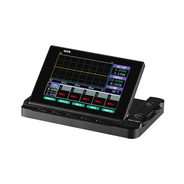
MDP-M01 is a display control module equipped with a 2.8-inch TFT display screen, the screen can be turned 90 degrees, which is convenient for users to view data and waveform. MDP-M01 can realize online display and control with MDP-P906 mini digital power supply modules and other modules of MDP system through 2.4 GHz wireless communication, and can control up to 6 sub-modules at the same time.
Specifications
Screen size
2.8' TFT
Screen resolution
240 x 320
Power
Micro USB power input, or taking power from sub-module via dedicated power cable
Input
DC 5 V/0.3 A
Other functions
Can control up to 6 sub-modulesUpgrade formware through Micro USB
Dimensions
107 x 66 x 13.6 mm
Weight
133 g
Included
1x MDP-M01 Smart Digital Monitor
1x Cable (2.5 mm jack to Micro USB)
Downloads
User Manual v3.4
Firmware v1.32
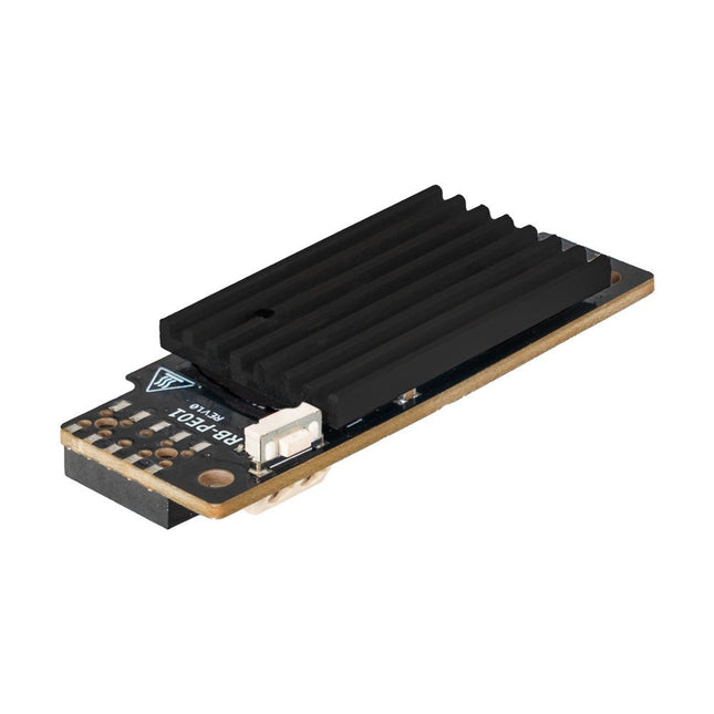
Wide Range Power Supply for Raspberry Pi
With the PiEnergy Mini, you can operate your Raspberry Pi with a voltage of 6 to 36 V DC. You can use the button integrated on the board to both power up and power down your Raspberry Pi.
Communication with the Raspberry Pi is via GPIO4, but this connection can also be cut by removing a resistor to use the pin freely. Thanks to the ultra-flat design, it can also be used in many housings. The pin header is included and not soldered on to keep the design even flatter.
Specifications
Input voltage
6 to 36 V DC
Output voltage
5.1 V
Output current
Up to 3 A (active ventilation recommended for additionally connected loads)
Cable cross-section at the power input
0.2-0.75 mm²
Interface to the Raspberry Pi
GPIO4
Microcontroller
ATtiny5
Further connections
5 V fan connector (2-pin/2.54 mm)Solder pads for external on/off switch
Compatible with
Raspberry Pi 3, 4, 5
Dimensions
23 x 56 x 11 mm
Included
Board with mounted heat sink
Pin header (2x5)
Spacer, screw, nut
Downloads
Datasheet (English)
Datasheet (Italiano)
Manual (English)
Manual (Italiano)
The X500 V2 ARF Kit is an affordable, lightweight, and robust carbon fiber professional drone kit that is easy to assemble (less than 15 minutes). It comes with the X500 V2 Frame Kit and motors, ESCs, power distribution boards and propellers preinstalled. It is perfectly compatible with various flight controllers such as the Holybro Pixhawk series, Durandal, Pix32 V5, etc. There are numerous improvements compared the previous model.
Specifications
Wheelbase: 500 mm
Motor mount pattern: 16x16 mm
Frame body: 144x144 mm, 2 mm thick
Landing gear height: 215 mm
Space between top and bottom plates: 28 mm
Weight: 610 g
Flight time: ~18 minutes hover with no additional payload. Tested with 5000 mAh battery.
Payload: 1500 g (without battery, 70% throttle)
Battery recommendation: 4S 3000-5000 mAh 20C+ with XT60 Lipo battery (not Included)
Included
X500 V2 Frame Kit
With Preinstalled Items:
4x Motors: Holybro 2216 KV920 Motor (4 pcs) with XT30 Plug
4x ESCs (BLHeli S ESC 20A)
6x 1045 Propellers
Power Distribution Board – XT60 plug for battery & XT30 plug for ESCs & peripherals
Note: Depth camera mount is sold separately.
SMA Straight Plug to SMA Straight Plug, 76.2 mm
Specifications
Frequency range
0 to 18 GHz VSWR (≤1.35)
Insertion loss
≤0,22 db
Body
Brass Nickel
Centre contact
Brass Gold
Insulator
PTFE
The only expendable component of the AxiDraw is the small, blue pen-lift servo motor. They do wear out over time but are straightforward to replace. For heavy duty applications, you may wish to keep a spare on hand. This replacement servo motor has been calibrated to the correct range, has the extended servo horn attached, and is ready to install. Includes a few cable ties to keep things neat. Compatible with: AxiDraw V3 AxiDraw V3/A3 AxiDraw SE/A3 AxiDraw V3 XLX Custom assembled AxiDraw models
The EiBotBoard ('EBB') is a USB-based dual stepper motor controller board that is useful for many general purpose robotics applications. Originally designed for the EggBot project, it is the 'brain' of all current models of the EggBot, but also of the AxiDraw and WaterColorBot as well. The EBB was designed by Brian Schmalz of Schmalz Haus LLC. It is an open source (in both hardware and software), PIC18F46J50-based motor controller board. Standard features include two Allegro A4983 16X microstepping motor drivers for bipolar steppers. It also has a separate onboard regulator to power up to two hobby servo motors. It is 2.2 x 2.2 inches square (5.6 x 5.6 cm). We are currently shipping version 2.7 of the EBB, which features several improvements for reliability. Version 2.7 uses a standard USB micro connector and has a switch that by default turns off power to the pen-lift servo motor after one minute of inactivity. You can change the timeout duration or disable this feature using the serial command protocol. Specifications Motor driver ICs: Two Allegro A4983 Stepper motor type: Bipolar (2) Step size: Full, 1/2, 1/4, 1/8, 1/16 Motor connectors: Screw terminal USB jack type: Micro-B Power connector: Barrel Jack, 2.1 x 5.5 mm, center positive Voltage input range: 9-25 V DC Output current adjustment: 46 mA to 1.25 A per phase Downloads/Documentation GitHub