Products
-
Elektor Digital C Programming for Embedded Microcontrollers (E-book)
Technology is constantly changing. New microcontrollers become available every year and old ones become redundant. The one thing that has stayed the same is the C programming language used to program these microcontrollers. If you would like to learn this standard language to program microcontrollers, then this book is for you! ARM microcontrollers are available from a large number of manufacturers. They are 32-bit microcontrollers and usually contain a decent amount of memory and a large number of on-chip peripherals. Although this book concentrates on ARM microcontrollers from Atmel, the C programming language applies equally to other manufacturer’s ARMs as well as other microcontrollers. Features of this book Use only free or open source software. Learn how to download, set up and use free C programming tools. Start learning the C language to write simple PC programs before tackling embedded programming - no need to buy an embedded system right away! Start learning to program from the very first chapter with simple programs and slowly build from there. No programming experience is necessary! Learn by doing - type and run the example programs and exercises. Sample programs and exercises can be downloaded from the Internet. A fun way to learn the C programming language. Ideal for electronic hobbyists, students and engineers wanting to learn the C programming language in an embedded environment on ARM microcontrollers.
€ 29,95
Members: € 26,96
-
Elektor Digital C Programming on Raspberry Pi (E-book)
Develop innovative hardware-based projects in C The Raspberry Pi has traditionally been programmed using Python. Although this is a very powerful language, many programmers may not be familiar with it. C on the other hand is perhaps the most commonly used programming language and all embedded microcontrollers can be programmed using it. The C language is taught in most technical colleges and universities and almost all engineering students are familiar with using it with their projects. This book is about using the Raspberry Pi with C to develop a range of hardware-based projects. Two of the most popular C libraries, wiringPi and pigpio are used. The book starts with an introduction to C and most students and newcomers will find this chapter invaluable. Many projects are provided in the book, including using Wi-Fi and Bluetooth to establish communication with smartphones. Many sensor and hardware-based projects are included. Both wiringPi and pigpio libraries are used in all projects. Complete program listings are given with full explanations. All projects have been fully tested and work. The following hardware-based projects are provided in the book: Using sensors Using LCDs I²C and SPI buses Serial communication Multitasking External and timer interrupts Using Wi-Fi Webservers Communicating with smartphones Using Bluetooth Sending data to the cloud Program listings of all Raspberry Pi projects developed in this book are available on the Elektor website. Readers can download and use these programs in their projects. Alternatively, they can customize them to suit their applications.
€ 32,95
Members: € 29,66
-
Elektor Digital C Programming with Arduino (E-book)
Technology is constantly changing. New microcontrollers become available every year. The one thing that has stayed the same is the C programming language used to program these microcontrollers. If you would like to learn this standard language to program microcontrollers, then this book is for you! Arduino is the hardware platform used to teach the C programming language as Arduino boards are available worldwide and contain the popular AVR microcontrollers from Atmel. Atmel Studio is used as the development environment for writing C programs for AVR microcontrollers. It is a full-featured integrated development environment (IDE) that uses the GCC C software tools for AVR microcontrollers and is free to download. At a glance: Start learning to program from the very first chapter No programming experience is necessary Learn by doing – type and run the example programs A fun way to learn the C programming language Ideal for electronic hobbyists, students and engineers wanting to learn the C programming language in an embedded environment on AVR microcontrollers Use the free full-featured Atmel Studio IDE software for Windows Write C programs for 8-bit AVR microcontrollers as found on the Arduino Uno and MEGA boards Example code runs on Arduino Uno and Arduino MEGA 2560 boards and can be adapted to run on other AVR microcontrollers or boards Use the AVR Dragon programmer/debugger in conjunction with Atmel Studio to debug C programs
€ 39,95
Members: € 35,96
-

Elektor Digital C# Programming for Windows and Android (E-book)
This e-book (pdf), a software-only follow up to the best-selling Elektor Visual Studio C# range of books, is aimed at Engineers, Scientists and Enthusiasts who want to learn about the C# language and development environment. It covers steps from installation, the .NET framework and object oriented programming, through to more advanced concepts including database applications, threading and multi-tasking, internet/network communications and writing DLLs. The DirectX chapters also include video capture. The e-book concludes with several chapters on writing Android applications in C# using the Xamarin add-on. This e-book is based on the Visual Studio 2015 development environment and latest C# additions including WPF applications, LINQ queries, Charts and new commands such as await and async. The latest Visual Studio debugging features (PerfTips, Diagnostic Tool window and IntellTrace) are covered. Finally, the Android chapters include GPS, E-mail and SMS applications. Additionally, the e-book provides free on-line access to extensive, well-documented examples — in a try for yourself style — together with links to the author’s videos, guiding you through the necessary steps to get the expected results.
€ 39,95
Members: € 35,96
-
Elektor Digital Camera Projects Book (E-book)
39 Experiments with Raspberry Pi and Arduino This book is about Raspberry Pi 3 and Arduino camera projects. The book explains in simple terms and with tested and working example projects, how to configure and use a Raspberry Pi camera and USB based webcam in camera-based projects using a Raspberry Pi. Example projects are given to capture images, create timelapse photography, record video, use the camera and Raspberry Pi in security and surveillance applications, post images to Twitter, record wildlife, stream live video to YouTube, use a night camera, send pictures to smartphones, face and eye detection, colour and shape recognition, number plate recognition, barcode recognition and many more. Installation and use of popular image processing libraries and software including OpenCV, SimpleCV, and OpenALPR are explained in detail using a Raspberry Pi. The book also explains in detail how to use a camera on an Arduino development board to capture images and then save them on a microSD card. All projects given in this book have been fully tested and are working. Program listings for all Raspberry Pi and Arduino projects used in this book are available for download on the Elektor website.
€ 29,95
Members: € 26,96
-
Elektor Digital Circuit Simulation with TINA Design Suite & TINACloud (E-book)
TINA Design Suite is a professional, powerful and affordable circuit simulator. It is a circuit designer and PCB design software package for analysing, designing, and real-time testing of analogue, digital, IBIS, VHDL, Verilog, Verilog AMS, SystemC, MCU, and mixed electronic circuits and their PCB layouts. In this book, top-selling Elektor author, Prof. Dr. Dogan Ibrahim aims to teach the design and analysis of electrical and electronic circuits and develop PCB boards using both TINA and TINACloud. The book is aimed at electrical/electronic engineers, undergraduate electronic/electrical engineering students at technical colleges and universities, postgraduate and research students, teachers, and hobbyists. Many tested and working simulation examples are provided covering most fields of analogue and digital electrical/electronic engineering. These include AC and DC circuits, diodes, zener diodes, transistor circuits, operational amplifiers, ladder diagrams, 3-phase circuits, mutual inductance, rectifier circuits, oscillators, active and passive filter circuits, digital logic, VHDL, MCUs, switch-mode power supplies, PCB design, Fourier series, and spectrum. Readers do not need to have any programming experience unless they wish to simulate complex MCU circuits.
€ 39,95
Members: € 35,96
-
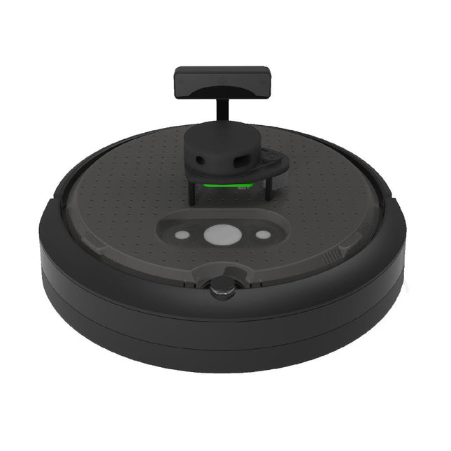
Clearpath Robotics Clearpath Robotics TurtleBot 4 Lite
TurtleBot 4 is the next-generation of the world’s most popular open source robotics platform for education and research, offering better computing power, better sensors and a world class user experience at an affordable price point.TurtleBot 4 Lite is equipped with an iRobot Create 3 mobile base, a powerful Raspberry Pi 4 running ROS 2, OAK-D spatial AI stereo camera, 2D LiDAR and more. All components have been seamlessly integrated to deliver an out-of-the-box development and learning platform.Specifications Base platform iRobot Create 3 Wheels (Diameter) 72 mm Ground Clearance 4.5 mm On-board Computer Raspberry Pi 4 (4 GB) Maximum linear velocity 0.31 m/s in safe mode0.46 m/s without safe mode Maximum angular velocity 1.90 rad/s Maximum payload 9 kg Operation time 2h 30m – 4h depending on load Charging time 2h 30m Lidar RPLIDAR A1M8 Camera OAK-D-Lite User Power VBAT @1.9 A5 V @ Low current3.3 V @ Low current USB Expansion 2x USB 2.0 (Type A)2x USB 3.0 (Type A) Programmable LEDs Create 3 Lightring Buttons and Switches 2x Create 3 User buttons1x Create 3 Power Button Battery 26 Wh Lithium Ion (14.4 V nominal) Charging Dock Included Size (L x W x H) 342 x 339 x 192 mm Weight 3.3 kg DownloadsUser Manual
€ 1.699,00
Best Price
-
Elektor Publishing Coding Modbus TCP/IP for Arduino
Example projects with Node-RED, MQTT, WinCC SCADA, Blynk, and ThingSpeak This comprehensive guide unlocks the power of Modbus TCP/IP communication with Arduino. From the basics of the Modbus protocol right up to full implementation in Arduino projects, the book walks you through the complete process with lucid explanations and practical examples. Learn how to set up Modbus TCP/IP communication with Arduino for seamless data exchange between devices over a network. Explore different Modbus functions and master reading and writing registers to control your devices remotely. Create Modbus client and server applications to integrate into your Arduino projects, boosting their connectivity and automation level. With detailed code snippets and illustrations, this guide is perfect for beginners and experienced Arduino enthusiasts alike. Whether you‘re a hobbyist looking to expand your skills or a professional seeking to implement Modbus TCP/IP communication in your projects, this book provides all the knowledge you need to harness the full potential of Modbus with Arduino. Projects covered in the book: TCP/IP communication between two Arduino Uno boards Modbus TCP/IP communication within the Node-RED environment Combining Arduino, Node-RED, and Blynk IoT cloud Interfacing Modbus TCP/IP with WinCC SCADA to control sensors Using MQTT protocol with Ethernet/ESP8266 Connecting to ThingSpeak IoT cloud using Ethernet/ESP8266
€ 39,95
Best Price
-

Elektor Digital Coding Modbus TCP/IP for Arduino (E-book)
Example projects with Node-RED, MQTT, WinCC SCADA, Blynk, and ThingSpeak This comprehensive guide unlocks the power of Modbus TCP/IP communication with Arduino. From the basics of the Modbus protocol right up to full implementation in Arduino projects, the book walks you through the complete process with lucid explanations and practical examples. Learn how to set up Modbus TCP/IP communication with Arduino for seamless data exchange between devices over a network. Explore different Modbus functions and master reading and writing registers to control your devices remotely. Create Modbus client and server applications to integrate into your Arduino projects, boosting their connectivity and automation level. With detailed code snippets and illustrations, this guide is perfect for beginners and experienced Arduino enthusiasts alike. Whether you‘re a hobbyist looking to expand your skills or a professional seeking to implement Modbus TCP/IP communication in your projects, this book provides all the knowledge you need to harness the full potential of Modbus with Arduino. Projects covered in the book: TCP/IP communication between two Arduino Uno boards Modbus TCP/IP communication within the Node-RED environment Combining Arduino, Node-RED, and Blynk IoT cloud Interfacing Modbus TCP/IP with WinCC SCADA to control sensors Using MQTT protocol with Ethernet/ESP8266 Connecting to ThingSpeak IoT cloud using Ethernet/ESP8266
€ 32,95
Members: € 29,66
-
Elektor Digital Computer Vision (EN) PDF
Computer vision is probably the most exciting branch of image processing, and the number of applications in robotics, automation technology and quality control is constantly increasing. Unfortunately entering this research area is, as yet, not simple. Those who are interested must first go through a lot of books, publications and software libraries. With this book, however, the first step is easy. The theoretically founded content is understandable and is supplemented by many practical examples. Source code is provided with the specially developed platform-independent open source library IVT in the programming language C/C++. The use of the IVT is not necessary, but it does make for a much easier entry and allows first developments to be quickly produced. The authorship is made up of research assistants of the chair of Professor Ruediger Dillmann at the Institut für Technische Informatik (ITEC), Universitaet Karlsruhe (TH). Having gained extensive experience in image processing in many research and industrial projects, they are now passing this knowledge on. Among other subjects, the following are dealt with in the fundamentals section of the book: Lighting, optics, camera technology, transfer standards, camera calibration, image enhancement, segmentation, filters, correlation and stereo vision. The practical section provides the efficient implementation of the algorithms, followed by many interesting applications such as interior surveillance, bar code scanning, object recognition, 3-D scanning, 3-D tracking, a stereo camera system and much more.
€ 19,95
Members: € 17,96
-
Elektor Publishing Consumer Electronics Repair, Reuse and Recycling
A Combat Guide against E-waste and Throwawayism This book is for anyone who enjoys tinkering with analog and digital hardware electronics. Regardless of the sophistication of your workspace, only basic tools are required to achieve truly satisfying results. It is intended as a reference guide among other hardware repair publications you may have in your library. However, the book goes a step further than most other repair guides in addressing issues in the modern era of discarded electronics called e-waste. E-waste should be put to good use. Producing anything new requires not just precious resources and labor, but also energy to make and deliver it to global retail shelves. Your talents and love of electronics can be put to good use by rescuing and resurrecting at least selected units from this endless stream of e-waste. Examples include either restoring through repair, or salvaging reusable electronic and mechanical components for your next project. Smart tips are provided throughout the book, and much information is tabulated for easy reference. The book expands age-old repair and hacking techniques applied for repair on the workbench into clever methods and applications to achieve effective results with discarded or “non-servicable” electronic consumer products. The final chapter provides real-life examples using all of the previously discussed content in a summarized form for each example repair type.
€ 39,95
Members: € 35,96
-

Elektor Digital Consumer Electronics Repair, Reuse and Recycling (E-book)
A Combat Guide against E-waste and Throwawayism This book is for anyone who enjoys tinkering with analog and digital hardware electronics. Regardless of the sophistication of your workspace, only basic tools are required to achieve truly satisfying results. It is intended as a reference guide among other hardware repair publications you may have in your library. However, the book goes a step further than most other repair guides in addressing issues in the modern era of discarded electronics called e-waste. E-waste should be put to good use. Producing anything new requires not just precious resources and labor, but also energy to make and deliver it to global retail shelves. Your talents and love of electronics can be put to good use by rescuing and resurrecting at least selected units from this endless stream of e-waste. Examples include either restoring through repair, or salvaging reusable electronic and mechanical components for your next project. Smart tips are provided throughout the book, and much information is tabulated for easy reference. The book expands age-old repair and hacking techniques applied for repair on the workbench into clever methods and applications to achieve effective results with discarded or “non-servicable” electronic consumer products. The final chapter provides real-life examples using all of the previously discussed content in a summarized form for each example repair type.
€ 32,95
Members: € 29,66
-

Elektor Publishing Control Engineering with Fuzzy Logic
Practical Applications and Project with Arduino, ESP32, and RP2040 Immerse yourself in the fascinating world of control engineering with Arduino and ESP32! This book offers you a practical introduction to classic and modern control methods, including PID controllers, fuzzy logic, and sliding-mode controllers. In the first part, you will learn the basics of the popular Arduino controllers, such as the Arduino Uno and the ESP32, as well as the integration of sensors for temperature and pH measurement (NTC, PT100, PT1000, and pH sensor). You will learn how to use these sensors in various projects and how to visualize data on a Nextion TFT display. The course continues with an introduction to actuators such as MOSFET switches, H-bridges, and solid-state relays, which are used to control motors and actuators. You will learn to analyze and model controlled systems, including PT1 and PT2 control. The book focuses on the implementation of fuzzy and PID controllers for controlling temperature and DC motors. Both the Arduino Uno and the ESP32 are used. The sliding-mode controller is also introduced. In the second-to-last chapter, you will explore the basics of neural networks and learn how machine learning can be used on an Arduino. In the last chapter, there is a practical example of a fuzzy controller for feeding electricity into the household grid. This book is the perfect choice for engineers, students, and electronics engineers who want to expand their projects with innovative control techniques.
€ 44,95
Members: € 40,46
-

Elektor Digital Control Engineering with Fuzzy Logic (E-book)
Practical Applications and Project with Arduino, ESP32, and RP2040 Immerse yourself in the fascinating world of control engineering with Arduino and ESP32! This book offers you a practical introduction to classic and modern control methods, including PID controllers, fuzzy logic, and sliding-mode controllers. In the first part, you will learn the basics of the popular Arduino controllers, such as the Arduino Uno and the ESP32, as well as the integration of sensors for temperature and pH measurement (NTC, PT100, PT1000, and pH sensor). You will learn how to use these sensors in various projects and how to visualize data on a Nextion TFT display. The course continues with an introduction to actuators such as MOSFET switches, H-bridges, and solid-state relays, which are used to control motors and actuators. You will learn to analyze and model controlled systems, including PT1 and PT2 control. The book focuses on the implementation of fuzzy and PID controllers for controlling temperature and DC motors. Both the Arduino Uno and the ESP32 are used. The sliding-mode controller is also introduced. In the second-to-last chapter, you will explore the basics of neural networks and learn how machine learning can be used on an Arduino. In the last chapter, there is a practical example of a fuzzy controller for feeding electricity into the household grid. This book is the perfect choice for engineers, students, and electronics engineers who want to expand their projects with innovative control techniques.
€ 34,95
Members: € 31,46
-
Elektor Digital Control Your Home with Raspberry Pi (E-book)
Secure, Modular, Open-Source and Self-Sufficient Ever since the Raspberry Pi was introduced, it has been used by enthusiasts to automate their homes. The Raspberry Pi is a powerful computer in a small package, with lots of interfacing options to control various devices. This book shows you how you can automate your home with a Raspberry Pi. You’ll learn how to use various wireless protocols for home automation, such as Bluetooth, 433.92 MHz radio waves, Z-Wave, and Zigbee. Soon you’ll automate your home with Python, Node-RED, and Home Assistant, and you’ll even be able to speak to your home automation system. All this is done securely, with a modular system, completely open-source, without relying on third-party services. You’re in control of your home, and no one else. At the end of this book, you can install and configure your Raspberry Pi as a highly flexible home automation gateway for protocols of your choice, and link various services with MQTT to make it your own system. This DIY (do it yourself) approach is a bit more laborious than just installing an off-the-shelf home automation system, but in the process, you can learn a lot, and in the end, you know exactly what’s running your house and how to tweak it. This is why you were interested in the Raspberry Pi in the first place, right? Turn your Raspberry Pi into a reliable gateway for various home automation protocols. Make your home automation setup reproducible with Docker Compose. Secure all your network communication with TLS. Create a video surveillance system for your home. Automate your home with Python, Node-RED, Home Assistant and AppDaemon. Securely access your home automation dashboard from remote locations. Use fully offline voice commands in your own language. Download the software and view the errata for the book on GitHub.
€ 34,95
Members: € 31,46
-

Elektor Digital Controller Area Network Projects (E-book)
The Controller Area Network (CAN) was originally developed to be used as a vehicle data bus system in passenger cars. Today, CAN controllers are available from over 20 manufacturers, and CAN is finding applications in other fields, such as medical, aerospace, process control, automation, and so on. This book is written for students, for practising engineers, for hobbyists, and for everyone else who may be interested to learn more about the CAN bus and its applications. The aim of this book is to teach you the basic principles of CAN networks and in addition the development of microcontroller based projects using the CAN bus. In summary, this book enables the reader to: Learn the theory of the CAN bus used in automotive industry Learn the principles, operation, and programming of microcontrollers Design complete microcontroller based projects using the C language Develop complete real CAN bus projects using microcontrollers Learn the principles of OBD systems used to debug vehicle electronics You will learn how to design microcontroller based CAN bus nodes, build a CAN bus, develop high-level programs, and then exchange data in real-time over the bus. You will also learn how to build microcontroller hardware and interface it to LEDs, LCDs, and A/D converters. The book assumes that the reader has some knowledge on basic electronics. Knowledge of the C programming language will be useful in later chapters of the book, and familiarity with at least one member of the PIC series of microcontrollers will be an advantage, especially if the reader intends to develop microcontroller based projects using the CAN bus.
€ 29,95
Members: € 26,96
-

Elektor Digital Controller Area Network Projects with ARM and Arduino (E-book)
This book details the use of the ARM Cortex-M family of processors and the Arduino Uno in practical CAN bus based projects. Inside, it gives a detailed introduction to the architecture of the Cortex-M family whilst providing examples of popular hardware and software development kits. Using these kits helps to simplify the embedded design cycle considerably and makes it easier to develop, debug, and test a CAN bus based project. The architecture of the highly popular ARM Cortex-M processor STM32F407VGT6 is described at a high level by considering its various modules. In addition, the use of the mikroC Pro for ARM and Arduino Uno CAN bus library of functions are described in detail. This book is written for students, for practising engineers, for hobbyists, and for everyone else who may need to learn more about the CAN bus and its applications. The book assumes that the reader has some knowledge of basic electronics. Knowledge of the C programming language will be useful in later chapters of the book, and familiarity with at least one microcontroller will be an advantage, especially if the reader intends to develop microcontroller based projects using CAN bus. The book should be useful source of reference to anyone interested in finding an answer to one or more of the following questions: What bus systems are available for the automotive industry? What are the principles of the CAN bus? What types of frames (or data packets) are available in a CAN bus system? How can errors be detected in a CAN bus system and how reliable is a CAN bus system? What types of CAN bus controllers are there? What are the advantages of the ARM Cortex-M microcontrollers? How can one create a CAN bus project using an ARM microcontroller? How can one create a CAN bus project using an Arduino microcontroller? How can one monitor data on the CAN bus?
€ 32,95
Members: € 29,66
-
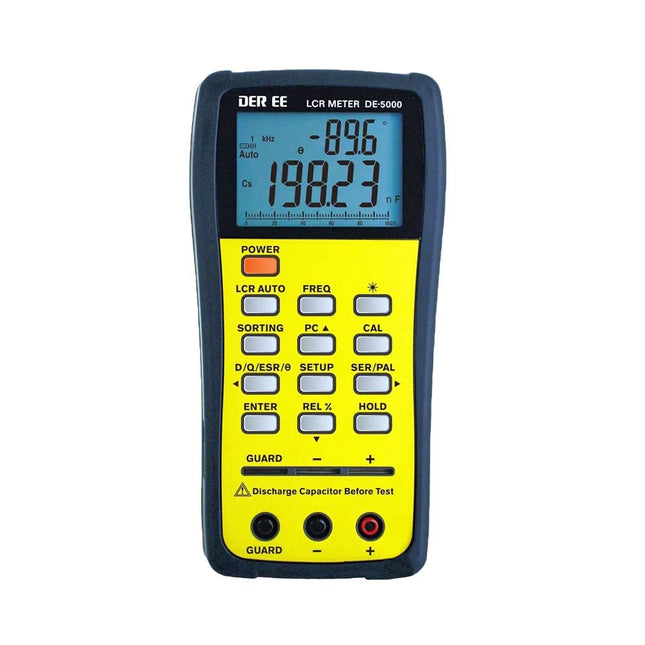
DER EE DER EE DE-5000 LCR Meter (100 kHz)
The DE-5000 is a smart, high-accurate, flexible and easy-to-use portable LCR meter. It features automatic LCR check, 4-wire Kelvin measurement, backlit display with 19999/1999 counts, multiple measurement modes and selectable test frequencies (100 Hz, 120 Hz, 1 kHz, 10 kHz or 100 kHz). The DE-5000 LCR meter is a practical helper for engineers or technicians. Features Auto L.C.R. check Ls/Lp/Cs/Cp/Rs/Rp/DCR with D/Q/θ/ESR measurement 4-wire Kelvin measurement 20,000 / 2,000 counts display Backlight Relative mode Series / Parallel modes Components sorting function Low battery indication Auto power off Specifications Test frequency 100 Hz / 120 Hz / 1 kHz / 10 kHz / 100 kHz Resistance range 20.000 Ω – 200.0 MΩ DCR range 200.00 Ω – 200.0 MΩ Capacitance range 200.00 pF – 20.00 mF Inductance range 20.000 µH – 2.000 KH Display (backlit LCD) 19999 / 1999 counts Selectable tolerance ±0.25%, ±0.5%, ±1%, ±2%, ±5%, ±10%, ±20% Power supply 9 V battery Dimensions 188 x 95 x 52 mm Weight 350 g (excluding battery) Included DE-5000 LCR meter Alligator test lead case (TL-21) AC/DC adaptor Guard line (TL-23) TL-22 SMD tweezers 9 V battery Carrying case Manual Downloads Datasheet
€ 192,39
-
Elektor Academy Pro Design PCBs Like a Pro
Learn KiCad with Peter Dalmaris The Academy Pro Box "Design PCBs like a Pro" offers a complete, structured training programme in PCB design, combining online learning with practical application. Based on Peter Dalmaris’ KiCad course, the 15-week programme integrates video lessons, printed materials (2 books), and hands-on projects to ensure participants not only understand the theory but also develop the skills to apply it in practice. Unlike standard courses, the Academy Pro Box provides a guided learning path with weekly milestones and physical components to design, test, and produce working PCBs. This approach supports a deeper learning experience and better knowledge retention. The box is ideal for engineers, students, and professionals who want to develop practical PCB design expertise using open-source tools. With the added option to have their final project manufactured, participants complete the programme with real results – ready for use, testing, or further development. Learn by doing Build skills. Design real boards. Generate Gerbers. Place your first order. This isn’t just a course – it’s a complete project journey from idea to product. You’ll walk away with: Working knowledge of KiCad’s tools Confidence designing your own PCBs A fully manufacturable circuit board – made by you What's inside the Box (Course)? Both volumes of "KiCad Like a Pro" (valued at €105) Vol 1: Fundamentals and Projects Vol 2: Advanced Projects and Recipes Coupon code to join the bestselling KiCad 9 online course by Peter Dalmaris on Udemy, featuring 20+ hours of video training. You'll complete three full design projects: Breadboard Power Supply Tiny Solar Power Supply Datalogger with EEPROM and Clock Voucher from Eurocircuits for the production of PCBs (worth €85 excl. VAT) Learning Material (of this Box/Course) 15-Week Learning Program ▶ Click here to open Week 1: Setup, Fundamentals, and First Steps in PCB Design Week 2: Starting Your First PCB Project – Schematic Capture Week 3: PCB Layout – From Netlist to Board Design Week 4: Design Principles, Libraries, and Workflow Week 5: Your First Real-World PCB Project Week 6: Custom Libraries – Symbols, Footprints, and Workflow Week 7: Advanced Tools – Net Classes, Rules, Zones, Routing Week 8: Manufacturing Files, BOMs, and PCB Ordering Week 9: Advanced Finishing Techniques – Graphics, Refinement, and Production Quality Week 10: Tiny Solar Power Supply – From Schematic to Layout Week 11: Tiny Solar Power Supply – PCB Layout and Production Prep Week 12: ESP32 Clone Project – Schematic Design and Layout Prep Week 13: ESP32 Clone – PCB Layout and Manufacturing Prep Week 14: Final Improvements and Advanced Features Week 15: Productivity Tools, Simulation, and Automation KiCad Course with 18 Lessons on Udemy (by Peter Dalmaris) ▶ Click here to open Introduction Getting started with PCB design Getting started with KiCad Project: A hands-on tour of KiCad (Schematic Design) Project: A hands-on tour of KiCad (Layout) Design principles and PCB terms Design workflow and considerations Fundamental KiCad how-to: Symbols and Eeschema Fundamental KiCad how-to: Footprints and Pcbnew Project: Design a simple breadboard power supply PCB Project: Tiny Solar Power Supply Project: MCU datalogger with build-in 512K EEPROM and clock Recipes KiCad 9 new features and improvements Legacy (from previous versions of KiCad) KiCad 7 update (Legacy) (Legacy) Gettings started with KiCad Bonus lecture About the Author Dr. Peter Dalmaris, PhD is an educator, an electrical engineer and Maker. Creator of online video courses on DIY electronics and author of several technical books. As a Chief Tech Explorer since 2013 at Tech Explorations, the company he founded in Sydney, Australia, Peter's mission is to explore technology and help educate the world. What is Elektor Academy Pro? Elektor Academy Pro delivers specialized learning solutions designed for professionals, engineering teams, and technical experts in the electronics and embedded systems industry. It enables individuals and organizations to expand their practical knowledge, enhance their skills, and stay ahead of the curve through high-quality resources and hands-on training tools. From real-world projects and expert-led courses to in-depth technical insights, Elektor empowers engineers to tackle today’s electronics and embedded systems challenges. Our educational offerings include Academy Books, Pro Boxes, Webinars, Conferences, and industry-focused B2B magazines – all created with professional development in mind. Whether you're an engineer, R&D specialist, or technical decision-maker, Elektor Academy Pro bridges the gap between theory and practice, helping you master emerging technologies and drive innovation within your organization.
-

Elektor Digital Design your own Embedded Linux Control Centre (E-book)
This book is all about building your own DIY home control system. It presents two innovative ways to assemble such a system: By recycling old PC hardware – possibly extending the life of an old PC, or by using Raspberry Pi. In both cases, the main system outlined in this book will consist of a computer platform, a wireless mains outlet, a controller and a USB webcam – All linked together by Linux. By using the Raspberry Pi in conjunction with Arduino (used as an advanced I/O system board), it is possible to construct a small, compact, embedded control system offering enhanced capacity for USB integration, webcams, thermal monitoring and communication with the outside world. The experience required to undertake the projects within this book are minimal exposure to PC hardware and software, the ability to surf the internet, burn a CD-ROM and assemble a small PCB.
€ 34,95
Members: € 31,46
-

Elektor Digital Designing Tube Amplifiers (E-book)
This book focuses more on practical aspects than on theory, and it has an contemplative nature, as though the author were viewing amplifiers from above. Knowledge elements are integrated and placed in the context of a broad overview. Even now tube amplifiers still sound great perhaps better than ever before. In part that is because we now have access to modern components such as toroidal output transformers, extremely high-quality resistors and capacitors, and many sorts of wire with good acoustic properties. Modern audio sources, such as CD players, and the latest top-end loudspeakers also enable us to appreciate how well tube amplifiers reproduce music even better than before. This new book from Menno van der Veen looks at tube amplifiers from more than just a theoretical perspective. It focuses primarily on the design phase, where decisions must be taken with regard to the purpose and requirements of the amplifier, and it addresses the following questions: How do these aspects relate to subjective and objective criteria? Which circuits sound the best, and why? If you want to develop and market an amplifier, what problems should you expect? What are the significance and meaning of measurements? Are they still meaningful, or have they lost their relevance? Thanks to the enormous processing power of computers, we can now measure more details than ever before. How can these new methods be applied to tube amplifiers? Previously it was sufficient to measure the frequency range, power and distortion of an amplifier in order to characterize the amplifier. Are these measurements still sufficient, or should we start measuring according to how we hear, using real music signals instead of waveforms from signal generators? The author sketches a future where amplifier measurements that conform to our sense of hearing enable us to arrive at new insights. This book focuses more on practical aspects than on theory, and it has an contemplative nature, as though the author were viewing amplifiers from above. Knowledge elements are integrated and placed in the context of a broad overview.
€ 29,95
Members: € 26,96
-
Elektor Digital Develop and Operate Your LoRaWAN IoT Nodes (E-book)
Ready-to-use devices and self-built Arduino nodes in the 'The Things Network' LoRaWAN has developed excellently as a communication solution in the IoT. The Things Network (TTN) has contributed to this. The Things Network was upgraded to The Things Stack Community Edition (TTS (CE)). The TTN V2 clusters were closed towards the end of 2021. This book shows you the necessary steps to operate LoRaWAN nodes using TTS (CE) and maybe extend the network of gateways with an own gateway. Meanwhile, there are even LoRaWAN gateways suitable for mobile use with which you can connect to the TTN server via your cell phone. The author presents several commercial LoRaWAN nodes and new, low-cost and battery-powered hardware for building autonomous LoRaWAN nodes. Registering LoRaWAN nodes and gateways in the TTS (CE), providing the collected data via MQTT and visualization via Node-RED, Cayenne, Thingspeak, and Datacake enable complex IoT projects and completely new applications at very low cost. This book will enable you to provide and visualize data collected with battery-powered sensors (LoRaWAN nodes) wirelessly on the Internet. You will learn the basics for smart city and IoT applications that enable, for example, the measurement of air quality, water levels, snow depths, the determination of free parking spaces (smart parking), and the intelligent control of street lighting (smart lighting), among others.
€ 32,95
Members: € 29,66
-
Elektor Publishing Develop your own Bluetooth Low Energy Applications
For Raspberry Pi, ESP32 and nRF52 with Python, Arduino and Zephyr Bluetooth Low Energy (BLE) radio chips are ubiquitous from Raspberry Pi to light bulbs. BLE is an elaborate technology with a comprehensive specification, but the basics are quite accessible. A progressive and systematic approach will lead you far in mastering this wireless communication technique, which is essential for working in low power scenarios. In this book, you’ll learn how to: Discover BLE devices in the neighborhood by listening to their advertisements. Create your own BLE devices advertising data. Connect to BLE devices such as heart rate monitors and proximity reporters. Create secure connections to BLE devices with encryption and authentication. Understand BLE service and profile specifications and implement them. Reverse engineer a BLE device with a proprietary implementation and control it with your own software. Make your BLE devices use as little power as possible. This book shows you the ropes of BLE programming with Python and the Bleak library on a Raspberry Pi or PC, with C++ and NimBLE-Arduino on Espressif’s ESP32 development boards, and with C on one of the development boards supported by the Zephyr real-time operating system, such as Nordic Semiconductor's nRF52 boards. Starting with a very little amount of theory, you’ll develop code right from the beginning. After you’ve completed this book, you’ll know enough to create your own BLE applications.
€ 39,95
Members: € 35,96
-
Elektor Digital Develop your own Bluetooth Low Energy Applications (E-book)
For Raspberry Pi, ESP32 and nRF52 with Python, Arduino and Zephyr Bluetooth Low Energy (BLE) radio chips are ubiquitous from Raspberry Pi to light bulbs. BLE is an elaborate technology with a comprehensive specification, but the basics are quite accessible. A progressive and systematic approach will lead you far in mastering this wireless communication technique, which is essential for working in low power scenarios. In this book, you’ll learn how to: Discover BLE devices in the neighborhood by listening to their advertisements. Create your own BLE devices advertising data. Connect to BLE devices such as heart rate monitors and proximity reporters. Create secure connections to BLE devices with encryption and authentication. Understand BLE service and profile specifications and implement them. Reverse engineer a BLE device with a proprietary implementation and control it with your own software. Make your BLE devices use as little power as possible. This book shows you the ropes of BLE programming with Python and the Bleak library on a Raspberry Pi or PC, with C++ and NimBLE-Arduino on Espressif’s ESP32 development boards, and with C on one of the development boards supported by the Zephyr real-time operating system, such as Nordic Semiconductor's nRF52 boards. Starting with a very little amount of theory, you’ll develop code right from the beginning. After you’ve completed this book, you’ll know enough to create your own BLE applications.
€ 32,95
Members: € 29,66


