Products
-

Elektor Publishing Apple Macintosh
20+ Macintosh Models, from 1984 to Today (History, Engineering, and Restoration) Apple is not like any other company. More than anyone else, it transformed technology into something people could desire, love, and even identify with—much like a luxury brand. Users were not only buying a tool; they were buying a vision, a way of life. At the center of this transformation stands the Macintosh. First introduced in 1984, it was radically different from everything before. With its graphical interface and mouse, it made computing approachable, even friendly. What now feels obvious—clicking on icons, dragging files, pointing instead of typing commands—was revolutionary at the time. The Macintosh not only changed the way people related to technology. The Macintosh forced the entire industry to rethink the way we use computers. This book tells that story through some of the most significant Macintosh models. Each one is presented not only in words but also in images, because these computers are more than technology—they are design icons, symbols of a unique vision. History, technical detail, and photography come together here, aiming to show each Macintosh as it truly deserves to be seen.
€ 79,95
Members: € 71,96
-

Elektor Digital Arduino & Co – Measure, Control, and Hack (E-book)
Clever Tricks with ATmega328 Pro Mini Boards With a simple Pro Mini board and a few other components, projects that 20 or 30 years ago were unthinkable (or would have cost a small fortune) are realized easily and affordably in this book: From simple LED effects to a full battery charging and testing station that will put a rechargeable through its paces, there’s something for everyone. All the projects are based on the ATmega328 microcontroller, which offers endless measuring, switching, and control options with its 20 input and output lines. For example, with a 7-segment display and a few resistors, you can build a voltmeter or an NTC-based thermometer. The Arduino platform offers the perfect development environment for programming this range of boards. Besides these very practical projects, the book also provides the necessary knowledge for you to create projects based on your own ideas. How to measure, and what? Which transistor is suitable for switching a certain load? When is it better to use an IC? How do you switch mains voltage? Even LilyPad-based battery-operated projects are discussed in detail, as well as many different motors, from simple DC motors to stepper motors. Sensors are another exciting topic: For example, a simple infrared receiver that can give disused remote controls a new lease on life controlling your home, and a tiny component that can actually measure the difference in air pressure between floor and table height!
€ 32,95
Members: € 29,66
-

Elektor Academy Pro Arduino (Programming Course)
This complete Arduino Uno-based microcontroller programming course features a textbook, a component kit, hands-on projects, and a comprehensive online course with simulations. It is ideal for step-by-step learning of embedded systems programming with Arduino using a practical, hands-on approach. A Practical Introduction to Embedded Systems with the Arduino Uno This course is designed for people who are new to embedded systems and looking for a structured, example-driven way to get started. A kit of parts comprising LEDs and resistors, switches, sensors and actuators, displays, a breadboard and wires, and more is included. These are used in the course to illustrate example applications. No prior experience with Arduino or embedded development is required. Each section features hands-on examples and mini projects designed to reinforce key concepts and inspire deeper exploration. By the end of the course, you’ll be able not only to reproduce the examples but also to build on them with your own ideas and applications. What Will You Learn? Microcontroller programming with Arduino using the Uno R3 board Working with Digital I/O, read buttons and encoders, control LEDs and relays Read analog inputs, voltages, and analog sensors Generating analog output signals and PWM Use serial communication like UART, I²C and SPI to control displays and read digital sensors and SD cards Managing time Working with interrupts Real-time sensor input and control via buttons, LEDs, and displays Control actuators like relays and servo motors Who Is It For? Students and self-learners exploring embedded systems Makers and IoT enthusiasts looking to improve their hardware skills Educators and trainers seeking ready-to-teach material What's Inside the Box? Access to the full course on the Elektor Academy Pro Learning Platform Uno R3 microcontroller board + USB cable Book: Programming Microcontrollers in C/C++ Using Arduino Downloadable project files for every module Component Box: 2× LED, red, 5 mm LED, green, 5 mm 3× Resistor, 470 Ω, 0.25 W LDR Potentiometer, 10 kΩ, linear Pushbutton Rotary encoder module Relay module DHT22 Humidity & Temperature Sensor TM1637-compatible 4-digit 7-segment display MPU-6050 IMU with headers SSD1306-compatible I²C OLED display Micro SD card adapter with header Buzzer SG90 Micro Servo ILI9341-compatible SPI 240×320 TFT display 20× Jumper wires Breadboard All Programming Courses (and differences in content) Course Arduino Raspberry Pi Pico with Arduino C/C++ ESP32 with Arduino C/C++ Raspberry Pi Pico with MicroPython ESP32 with MicroPython Online Course Access to Arduino Course Access to Pico with Arduino C/C++ Course Access to ESP32 with Arduino C/C++ Course Access to Pico with MicroPython Course Access to ESP32 with MicroPython Course Board Uno R3 Raspberry Pi Pico ESP32 Raspberry Pi Pico ESP32 Book Programming Microcontrollers in C/C++ Using Arduino Programming Microcontrollers in C/C++ Using Arduino Programming Microcontrollers in C/C++ Using Arduino Programming Microcontrollers in MicroPython Programming Microcontrollers in MicroPython Kit 40-piece Component Box 40-piece Component Box 40-piece Component Box 40-piece Component Box 40-piece Component Box
€ 69,95€ 59,95
Best Price
-
Elektor Digital Arduino 8-bit Sound Generation (E-book)
Arduinonext is an initiative powered by an electronics and microcontrollers specialist team aiming to help all those who are entering in the technology world, using the well-known Arduino platform to take the next step in electronics. We strive to bring you the necessary knowledge and experience for developing your own electronics applications; interacting with environment; measuring physical parameters; processing them and performing the necessary control actions. This is the first title in the 'Hands-On' series in which Arduino platform co-founder, David Cuartielles, introduces board programming, and demonstrates the making of an 8-bit Sound Generator.
€ 7,95
Members: € 7,16
-
Elektor Digital Arduino Compilation (EN) | E-book
This 233-page e-book is packed with Arduino ideas, explanations, tips, diagrams, programs, PCB layouts, and more – enough to provide days of informative, inspiring, and stimulating reading pleasure! The PDF document includes a table of contents with links to the individual projects, allowing you to easily navigate to the sections you’re most interested in. This way, you can quickly and effortlessly switch between projects and find exactly what you’re looking for.
€ 9,95
Members: € 8,96
-
Elektor Publishing Arduino for Radio Amateur Applications
Program and build Arduino-based ham station utilities, tools, and instruments In addition to a detailed introduction to the exciting world of the Arduino microcontroller and its many variants, this book introduces you to the shields, modules, and components you can connect to the Arduino. Many of these components are discussed in detail and used in the projects included in this book to help you understand how these components can be incorporated into your own Arduino projects. Emphasis has been placed on designing and creating a wide range of amateur radio-related projects that can easily be built in just a few days. This book is written for ham radio operators and Arduino enthusiasts of all skill levels, and includes discussions about the tools, construction methods, and troubleshooting techniques used in creating amateur radio-related Arduino projects. The book teaches you how to create feature-rich Arduino-based projects, with the goal of helping you to advance beyond this book, and design and build your own ham radio Arduino projects. In addition, this book describes in detail the design, construction, programming, and operation of the following projects: CW Beacon and Foxhunt Keyer Mini Weather Station RF Probe with LED Bar Graph DTMF Tone Encoder DTMF Tone Decoder Waveform Generator Auto Power On/Off Bluetooth CW Keyer Station Power Monitor AC Current Monitor This book assumes a basic knowledge of electronics and circuit construction. Basic knowledge of how to program the Arduino using its IDE will also be beneficial.
€ 39,95
Members: € 35,96
-
Elektor Digital Arduino for Radio Amateur Applications (E-book)
Program and build Arduino-based ham station utilities, tools, and instruments In addition to a detailed introduction to the exciting world of the Arduino microcontroller and its many variants, this book introduces you to the shields, modules, and components you can connect to the Arduino. Many of these components are discussed in detail and used in the projects included in this book to help you understand how these components can be incorporated into your own Arduino projects. Emphasis has been placed on designing and creating a wide range of amateur radio-related projects that can easily be built in just a few days. This book is written for ham radio operators and Arduino enthusiasts of all skill levels, and includes discussions about the tools, construction methods, and troubleshooting techniques used in creating amateur radio-related Arduino projects. The book teaches you how to create feature-rich Arduino-based projects, with the goal of helping you to advance beyond this book, and design and build your own ham radio Arduino projects. In addition, this book describes in detail the design, construction, programming, and operation of the following projects: CW Beacon and Foxhunt Keyer Mini Weather Station RF Probe with LED Bar Graph DTMF Tone Encoder DTMF Tone Decoder Waveform Generator Auto Power On/Off Bluetooth CW Keyer Station Power Monitor AC Current Monitor This book assumes a basic knowledge of electronics and circuit construction. Basic knowledge of how to program the Arduino using its IDE will also be beneficial.
€ 32,95
Members: € 29,66
-
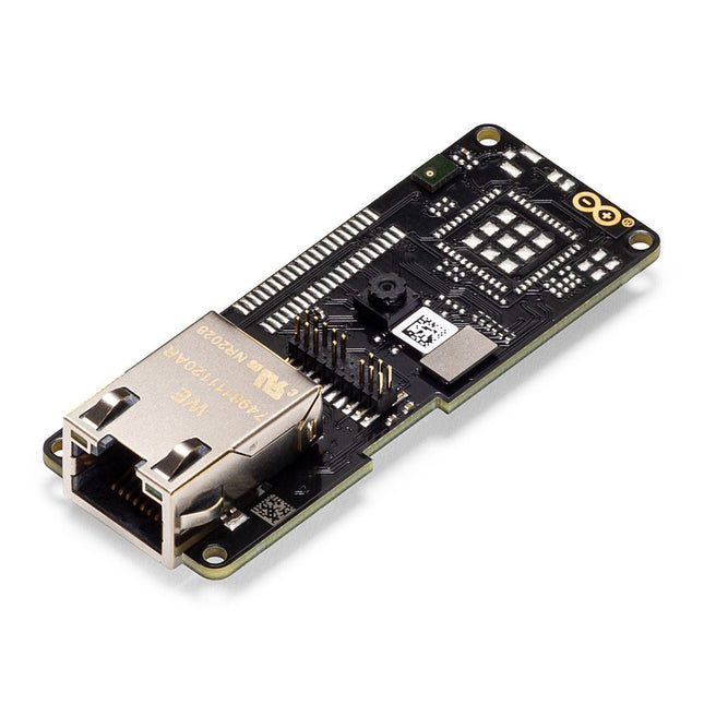
Arduino Arduino Pro Portenta Vision Shield (Ethernet)
The Arduino Pro Portenta Vision Shield brings industry-rated features to your Portenta. This hardware add-on will let you run embedded computer vision applications, connect wirelessly or via Ethernet to the Arduino Cloud or your own infrastructure, and activate your system upon the detection of sound events. Features 324x324 pixels camera sensor: use one of the cores in Portenta to run image recognition algorithms using the OpenMV for Arduino editor 100 Mbps Ethernet connector: get your Portenta H7 connected to the wired Internet 2 onboard microphones for directional sound detection: capture and analyse sound in real-time JTAG connector: perform low-level debugging of your Portenta board or special firmware updates using an external programmer SD-Card connector: store your captured data in the card, or read configuration files The Vision Shield has been designed to fit on top of the Arduino Portenta family. The Portenta boards feature multicore 32-bit ARM Cortex processors running at hundreds of megahertz, with megabytes of program memory and RAM. Portenta boards come with WiFi and Bluetooth. Embedded Computer Vision Made Easy Arduino has teamed up with OpenMV to offer you a free license to the OpenMV IDE, an easy way into computer vision using MicroPython as a programming paradigm. Download the OpenMV for Arduino Editor from our professional tutorials site and browse through the examples we have prepared for you inside the OpenMV IDE. Companies across the whole world are already building their commercial products based on this simple-yet-powerful approach to detect, filter, and classify images, QR codes, and others. Debugging With Professional Tools Connect your Portenta H7 to a professional debugger through the JTAG connector. Use professional software tools like the ones from Lauterbach or Segger on top of your board to debug your code step by step. The Vision Shield exposes the required pins for you to plug in your external JTAG. Camera Himax HM-01B0 camera module Resolution 320 x 320 active pixel resolution with support for QVGA Image sensor High sensitivity 3.6μ BrightSense pixel technology Microphone 2 x MP34DT05 Length 66 mm Width 25 mm Weight 11 gr For more information, check out the tutorials provided by Arduino here.
€ 69,95€ 19,95
Best Price
-
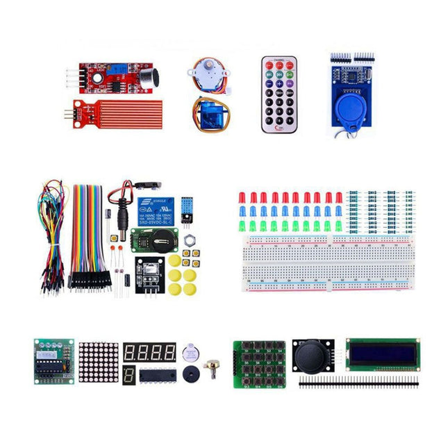
Makerfabs Arduino Uno Experimenting Kit
With this kit you can built all the projects described in the book 'Mastering the Arduino Uno R4'. The kit comes with several LEDs, sensors, actuators, and other components. The purpose of the kit is to make a flying start with hardware and software aspects of projects designed around the Arduino Uno microcontroller system. Included 1x RFID reader module 1x DS1302 clock module 1x 5 V stepper motor 1x '2003' stepper motor drive board 5x Green LED 5x Yellow LED 5x Red LED 2x Rocker switch 1x Flame sensor 1x LM35 sensor module 1x Infrared receiver 3x Light-dependent resistors (LDRs) 1x IR remote controller 1x Breadboard 4x Pushbutton (with four caps) 1x Buzzer 1x Piezo sounder 1x Adjustable resistor (potentiometer) 1x 74HC595 shift register 1x 7-segment display 1x 4-digit 7-segment display 1x 8x8 Dot-matrix display 1x 1602 / I²C LCD module 1x DHT11 Temperature and humidity module 1x Relay module 1x Sound module Set of Dupont cables Set of Breadboard cables 1x Water sensor 1x PS2 Joystick 5x 1 k-ohm resistor 5x 10 k-ohm resistor 5x 220-ohm resistor 1x 4x4 keypad module 1x 9g Servo (25 cm) 1x RFID card 1x RGB module 1x 9 V battery DC jack Not included Mastering the Arduino Uno R4 (Book) Arduino Uno R3/R4 (Board)
-

Elektor Bundles Arduino UNO Q (Bundle)
This bundle includes the Arduino UNO Q (2 GB) and the new book "Arduino UNO Q and AI". The Arduino UNO Q is the first UNO board with a hybrid dual-brain architecture, combining a powerful Linux processor with a real-time microcontroller – bringing advanced computing and precise control together on one board. Powered by a Qualcomm Dragonwing QRB2210 MPU running Debian Linux and a STM32U585 MCU for real-time tasks, the UNO Q is built for next-generation applications. From Edge Computing and AI to robotics and automation, it delivers high performance without sacrificing ease of use. Simply connect your peripherals and get started – no extra hardware required. Features Dual-core architecture: Linux MPU + real-time MCU Qualcomm Dragonwing QRB2210 with Debian Linux support STM32U585 microcontroller for deterministic control Runs Arduino sketches via Zephyr OS Ideal for AI, IoT, robotics, and industrial projects Specifications Microprocessor (MPU) Qualcomm Dragonwing QRB2210:Quad-core Arm Cortex-A53 @ 2.0 GHzAdreno GPU 3D graphics accelerator2× ISP (13 MP + 13 MP or 25 MP) @ 30 fps Microcontroller (MCU) STM32U585Arm Cortex-M33 up to 160 MHz2 MB flash memory786 KB SRAM RAM 2 GB LPDDR4 Power Supply From USB-C connector 5 V max at 3 AInput Voltage (VIN): 7-24 V Storage 16 GB eMMC USB 1× USB-C port with host/device role switching, power role switch and video output Connectivity Wi-Fi 5 (2.4/5 GHz) with onboard antennaBluetooth 5.1 with onboard antenna Interfaces I²C/I³CSPIPWMCANUARTPSSIGPIOJTAGADC Video Video output support via USB-CMIPI DSI pins on JMEDIA header Extra 4× RGB user-controllable LEDs8×13 Blue LED Matrix1× Qwiic connector voltage 3V3, I²C1× User push-buttonJCTL: MPU Remote Debug connector Audio Microphone IN / Headphone OUT / Line OUT on JMISC MPU Operating System Linux Debian OS with upstream support Real-time Operating System Arduino Core on Zephyr OS Containerization Docker and Docker Compose support Support Operating Systems for Arduino App Lab Windows: Windows 10 or later (64-bit)macOS: macOS 11 or later (64-bit)Linux: Ubuntu 22.04 or later, and Debian Trixie (64-bit) Dimensions 68.85 × 53.34 mm (UNO form factor) Downloads Datasheet User Manual Pinout Schematics Book: Arduino UNO Q and AI – Learn to Build Intelligent Embedded Systems Build smarter embedded systems with Arduino UNO Q. This book gives you the tools, knowledge, and confidence to turn ideas into intelligent, working solutions using the Arduino UNO Q platform. Discover how to build intelligent embedded systems with the Arduino UNO Q and AI. Unlock the full potential of the Arduino UNO Q, a next-generation platform that combines the real-time power of the STM32U585 microcontroller with the flexibility of a Qualcomm Dragonwing QRB2210 microprocessor. Learn how to rapidly prototype real-world applications using the Arduino IDE for low-level embedded control and Python in Arduino App Lab for high-level development. Build confidence through hands-on projects that guide you step by step from basic board features to complete working systems. Explore ready-to-use, AI based Arduino App Lab examples and see how they can jump-start your development and reduce time to deployment. Step into the world of Edge AI with a clear, practical introduction to Edge Impulse Studio—no prior AI experience required. Follow a complete, real-world workflow to create a Keyword Spotting AI application, covering data collection, model training, optimization, and on-device inference using the Edge Impulse Studio. Bridge the gap between embedded systems and machine learning and learn how to bring intelligence directly onto your hardware. Perfect for embedded engineers, educators, students, and makers looking to stay ahead in AI-enabled product development. This bundle contains: Arduino UNO Q (2 GB) (normal price: €50) Book: Arduino UNO Q and AI (normal price: €35)
€ 84,95€ 74,95
Best Price
-

Elektor Publishing Arduino UNO Q and AI
Learn to Build Intelligent Embedded Systems Build smarter embedded systems with Arduino UNO Q. This book gives you the tools, knowledge, and confidence to turn ideas into intelligent, working solutions using the Arduino UNO Q platform. Discover how to build intelligent embedded systems with the Arduino UNO Q and AI. Unlock the full potential of the Arduino UNO Q, a next-generation platform that combines the real-time power of the STM32U585 microcontroller with the flexibility of a Qualcomm Dragonwing QRB2210 microprocessor. Learn how to rapidly prototype real-world applications using the Arduino IDE for low-level embedded control and Python in Arduino App Lab for high-level development. Build confidence through hands-on projects that guide you step by step from basic board features to complete working systems. Explore ready-to-use, AI based Arduino App Lab examples and see how they can jump-start your development and reduce time to deployment. Step into the world of Edge AI with a clear, practical introduction to Edge Impulse Studio—no prior AI experience required. Follow a complete, real-world workflow to create a Keyword Spotting AI application, covering data collection, model training, optimization, and on-device inference using the Edge Impulse Studio. Bridge the gap between embedded systems and machine learning and learn how to bring intelligence directly onto your hardware. Perfect for embedded engineers, educators, students, and makers looking to stay ahead in AI-enabled product development.
€ 34,95
Members: € 31,46
-

Elektor Digital Arduino UNO Q and AI (E-book)
Learn to Build Intelligent Embedded Systems Build smarter embedded systems with Arduino UNO Q. This book gives you the tools, knowledge, and confidence to turn ideas into intelligent, working solutions using the Arduino UNO Q platform. Discover how to build intelligent embedded systems with the Arduino UNO Q and AI. Unlock the full potential of the Arduino UNO Q, a next-generation platform that combines the real-time power of the STM32U585 microcontroller with the flexibility of a Qualcomm Dragonwing QRB2210 microprocessor. Learn how to rapidly prototype real-world applications using the Arduino IDE for low-level embedded control and Python in Arduino App Lab for high-level development. Build confidence through hands-on projects that guide you step by step from basic board features to complete working systems. Explore ready-to-use, AI based Arduino App Lab examples and see how they can jump-start your development and reduce time to deployment. Step into the world of Edge AI with a clear, practical introduction to Edge Impulse Studio—no prior AI experience required. Follow a complete, real-world workflow to create a Keyword Spotting AI application, covering data collection, model training, optimization, and on-device inference using the Edge Impulse Studio. Bridge the gap between embedded systems and machine learning and learn how to bring intelligence directly onto your hardware. Perfect for embedded engineers, educators, students, and makers looking to stay ahead in AI-enabled product development.
€ 29,95
Members: € 26,96
-

Elektor Bundles Arduino Uno R4 WiFi (Bundle)
Book: Mastering the Arduino Uno R4 Based on the low-cost 8-bit ATmega328P processor, the Arduino Uno R3 board is likely to score as the most popular Arduino family member, and this workhorse has been with us for many years. Eleven years later, the long-overdue successor, the Arduino Uno R4, was released. It is built around a 48 MHz, 32-bit Arm Cortex-M4 microcontroller and provides significantly expanded SRAM and Flash memory. Additionally, a higher-precision ADC and a new DAC are added to the design. The Uno R4 board also supports the CAN Bus with an interface. Two versions of the board are available: Uno R4 Minima, and Uno R4 WiFi. This book is about using these new boards to develop many different and interesting projects with just a handful of parts and external modules. All projects described in the book have been fully tested on the Uno R4 Minima or the Uno R4 WiFi board, as appropriate. The project topics include the reading, control, and driving of many components and modules in the kit as well as on the relevant Uno R4 board, including LEDs 7-segment displays (using timer interrupts) LCDs Sensors RFID Reader 4x4 Keypad Real-time clock (RTC) Joystick 8×8 LED matrix Motors DAC (Digital-to-analog converter) LED matrix WiFi connectivity Serial UART CAN bus Infrared controller and receiver Simulators … all in creative and educational ways with the project operation and associated software explained in great detail. Arduino Uno R4 WiFi The Arduino Uno R4 is powered by the Renesas RA4M1 32-bit ARM Cortex-M4 processor, providing a significant boost in processing power, memory, and functionality. The WiFi version comes with an ESP32-S3 WiFi module in addition to the RA4M1, expanding creative opportunities for makers and engineers. The Arduino Uno R4 runs at 48 MHz, which provides a 3x increase over the popular Uno R3. Additionally, SRAM has been upgraded from 2 kB to 32 kB, and flash memory from 32 kB to 256 kB to support more complex projects. Responding to community feedback, the USB port is now USB-C, and the maximum power supply voltage has been raised to 24 V with an enhanced thermal design. The board includes a CAN bus and an SPI port, enabling users to reduce wiring and perform parallel tasks by connecting multiple shields. A 12-bit analog DAC is also provided on the board. Specifications Microcontroller Renesas RA4M1 (ARM Cortex-M4) USB USB-C Programming Port Pins Digital I/O Pins 14 Pins Analog input pins 6 DAC 1 RTC 1 PWM pins 6 Communication UART 1x I²C 1x SPI 1x Qwiic I²C connector 1x CAN 1x CAN Bus Power Circuit operating voltage 5 V Input voltage (VIN) 6-24 V DC Current per I/O Pin 8 mA Clock speed Main core 48 MHz Memory RA4M1 256 kB Flash, 32 kB RAM LED Matrix 12 x 8 (96 red LEDs) Dimensions 68.9 x 53.4 mm Downloads Datasheet Schematics This bundle contains: Book: Mastering the Arduino Uno R4 (normal price: €45) Arduino Uno R4 WiFi (normal price: €30)
€ 74,95€ 64,95
Best Price
-

Elektor Digital Arduino Uno – 45 Projects for Beginners and Experts (E-book)
This book covers a series of exciting and fun projects for the Arduino, such as a silent alarm, people sensor, light sensor, motor control, internet and wireless control (using a radio link). Contrary to many free projects on the internet all projects in this book have been extensively tested and are guaranteed to work! You can use it as a projects book and build more than 45 projects for your own use. The clear explanations, schematics, and pictures of each project make this a fun activity. The pictures are taken of a working project, so you know for sure that they are correct. You can combine the projects in this book to make your own projects. To facilitate this, clear explanations are provided on how the project works and why it has been designed the way it has That way you will learn a lot about the project and the parts used, knowledge that you can use in your own projects. Apart from that, the book can be used as a reference guide. Using the index, you can easily locate projects that serve as examples for the C++ commands and Arduino functionality. Even after you’ve built all the projects in this book, it will still be a valuable reference guide to keep next to your PC.
€ 29,95
Members: € 26,96
-
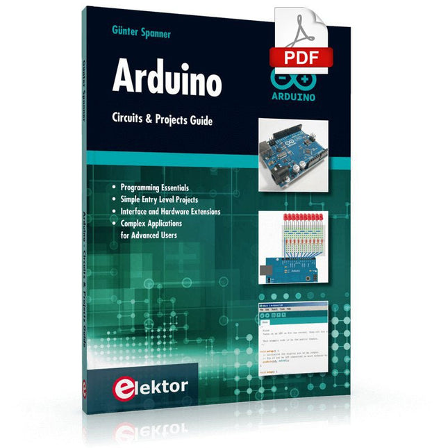
Elektor Digital Arduino – Circuits & Projects Guide (E-book)
Two reasons can be identified for the immense success of the Arduino platform. First, the cheap, ready to go processor board greatly simplifies the introduction to hardware. The second success factor is the free and open-source programming suite that does not require an installation procedure. Simple entry-level examples ensure rapid successes. Complex selection procedures for parameters like the microprocessor version or interface settings are not required. The first sample programs can be uploaded to the Arduino board, and tested, in a matter of minutes. The Arduino user is supported by an array of software libraries. However, the daily increasing volume of libraries poses initial problems to the newcomer, and the way ahead may be uncertain after a few entry-level examples. In many cases, detailed descriptions are missing, and poorly described projects tend to confuse rather than elucidate. Clear guidance and a single motto are missing, usually owing to the projects having been created by several different persons—all with different aims in mind. This book represents a different approach. All projects are presented in a systematical manner, guiding into various theme areas. In the coverage of must-know theory great attention is given to practical directions users can absorb, including essential programming techniques like A/D conversion, timers and interrupts—all contained in the hands-on projects. In this way readers of the book create running lights, a wakeup light, fully functional voltmeters, precision digital thermometers, clocks of many varieties, reaction speed meters, or mouse controlled robotic arms. While actively working on these projects the reader gets to truly comprehend and master the basics of the underlying controller technology.
€ 29,95
Members: € 26,96
-
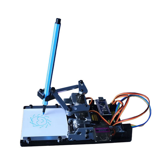
Generic Arduino-controlled Drawing Robot
This versatile plotter robot arm DIY kit for Arduino is equipped with MG90S metal gear servo motors to ensure precise and stable drawing movements. Features Fully compatible with Arduino IDE, includes complete source code for easy development and customization. Equipped with robust MG90S metal gear servo motors for accuracy and durability. Includes a Bluetooth module enabling wireless operation via a dedicated app. Specially designed robotic arm tip securely holds pens or markers with a diameter of 8-10 mm, ideal for sketches and detailed drawings. Included Arduino-compatible Nano motherboard Nano expansion board Bluetooth module MG90S all-metal gear servo motors Aluminum structural frame Thickened stable base plate Screw and fastening accessories Connecting wires USB data cable
-
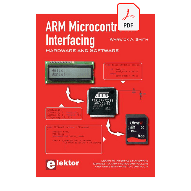
Elektor Digital ARM Microcontroller Interfacing (E-book)
Learn to interface and program hardware devices in a wide range of useful applications, using ARM7 microcontrollers and the C programming language. Examples covered in full detail include a simple LED to a multi-megabyte SD card running the FAT file system. Features of this book Build prototype circuits on breadboard or Veroboard and interface to ARM microcontrollers. A 32-bit ARM7 microcontroller is used in interfacing and software examples. Interfacing principles apply to other ARM microcontrollers and other non-ARM microcontrollers as well. Example programs are written in the C programming language. Use only free or open source software. Download and install all programming tools from the Internet. Template project files are provided for easy project creation. Hardware Interface to LEDs, transistors, optocouplers, relays, solenoids, switches, keypads, LCD displays, seven segment displays, DC motors, stepper motors, external analogue signals using the ADC, RS232, RS-485, TWI, USB, SPI and SD memory cards. Software Once hardware has been interfaced to a microcontroller, software must be written to control the hardware. You will learn how to write programs to operate externally interfaced hardware devices, use timers and interrupts. Also learn how to port FAT file system code for use with an SD memory card, program the PWM to produce an audio sine wave, program the PWM to speed control a DC motor and more. A chapter on more advanced ARM microcontrollers is included with an overview of some of the newest ARM microcontrollers and their features.
€ 29,95
Members: € 26,96
-
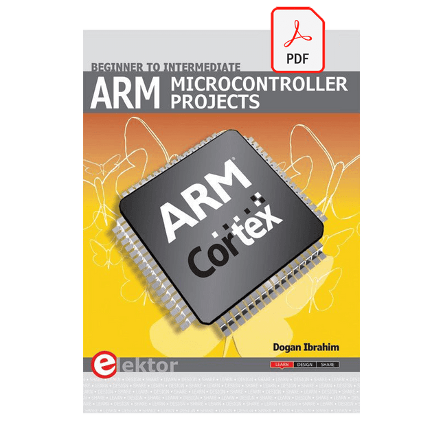
Elektor Digital ARM Microcontroller Projects (E-book)
It is becoming important for microcontroller users to quickly learn and adapt to new technologies and architecture used in high performance 32-bit microcontrollers. Many manufacturers now offer 32-bit microcontrollers as general purpose processors in embedded applications. ARM provide 32 and 64-bit processors mainly for embedded applications. These days, the majority of mobile devices including mobile phones, tablets, and GPS receivers are based on ARM technology. The low cost, low power consumption, and high performance of ARM processors makes them ideal for use in complex communication and mixed signal applications. This book makes use of the ARM Cortex-M family of processors in easy-to-follow, practical projects. It gives a detailed introduction to the architecture of the Cortex-M family. Examples of popular hardware and software development kits are described. The architecture of the highly popular ARM Cortex-M processor STM32F107VCT6 is described at a high level, taking into consideration its clock mechanisms, general input/output ports, interrupt sources, ADC and DAC converters, timer facilities, and more. The information provided here should act as a basis for most readers to start using and programming the STM32F107VCT6 microcontroller together with a development kit. Furthermore, the use of the mikroC Pro for ARM integrated development environment (IDE) has been described in detail. This IDE includes everything required to create a project; namely an editor, compiler, simulator, debugger, and device programmer. Although the book is based on the STM32F107VCT6 microcontroller, readers should not find it difficult to follow the projects using other ARM processor family members.
€ 34,95
Members: € 31,46
-
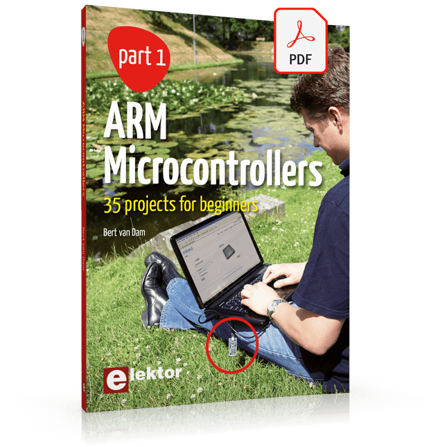
Elektor Digital ARM Microcontrollers (EN) | E-book
35 Projects for Beginners This book is for hobbyists, students and engineers who want to learn C and how to use an mbed ARM microcontroller in an easy and fun way, without the need for cumbersome software installations. ARM mbed microcontroller NXP LPC1768 The projects in this book are meant for beginners in C and ARM microcontrollers. That doesn't mean the projects are simple, but it does mean that they are easy to understand. We use for example USB communications, a subject that is made so easy by the mbed that it is suitable for a beginners book. Cloud technology The mbed NXP LPC1768 uses cloud technology, a revolutionary concept in software development. This means you do not need to install software on your PC in order to program the mbed! The only thing you need is a browser such as Microsoft Internet Explorer, and a USB port on your PC. You can get access to your project from any PC anywhere in the world and continue working on it. When you are done a few simple mouse clicks transfer the program to your mbed hardware. Of course you can optionally download the projects and store them on your own PC. Features of this Book Learn how to program an mbed ARM microcontroller using cloud technology. No complicated software installation on your PC needed. Learn programming in C by doing fun and interesting projects. No previous experience or knowledge required. Examples of projects in this book: flashing light, timer, light activated switch, digital thermometer, people detector, USB communication, talking microcontroller, debugging, sound switch, and much more - 35 projects in total. Examples of C subjects in this book: variables, commands, functions, program execution, pointers (introduction).
€ 29,95
Members: € 26,96
-

Elektor Digital Artificial Intelligence (E-book)
23 projects to bring your microcontroller to life! This book contains 23 special and exciting artificial intelligence machine-learning projects, for microcontroller and PC. Learn how to set up a neural network in a microcontroller, and how to make the network self-learning. Discover how you can breed robots, and how changing a fitness function results in a totally different behavior. Find out how a PC program exposes your weak spots in a game, and ruthlessly exploits them. Build a free-will robot, or have one clean your floor! Example projects from the book: A microcontroller that learns what your favourite color is. A robot wandering about the house looking for someone to play with. A bred robot program that is incapable of crossing a black line. A microcontroller that learns how to play a game until You just can't win anymore. A PC that programs a microcontroller all by itself. Complete with free software that you can download containing: All source code for the microcontroller. All sources of compiled PC programs (MS Windows). JAL programming language, with special editor and extension libraries. Robot breed program. Plus a support webpage with links, errata and FAQ. Several artificial intelligence techniques are discussed and used in projects such as expert system, neural network, subsumption, emerging behavior, genetic algorithm, cellular automata and roulette brains. Every project has clear instructions and pictures so you can start immediately. Suggestions and literature links allow you to go way beyond the scope of the book. Even after you have built all the projects contained within, this book will remain a valuable reference guide to keep next to your PC. A unique book for anyone with an interest in artificial intelligence and machine learning.
€ 29,95
Members: € 26,96
-

Elektor Digital Assembly Language Essentials (E-book)
A Guide to Powerful Programming for Embedded Systems You must be a well-rounded professional to excel in the ever-evolving, rapidly developing embedded design and programming industry. Simply put, when it comes to electronics design and programming, the more topics you can master, the more you’ll flourish at your workplace and at your personal workbench. This shouldn’t be a surprise, as the line between the skills of a hardware engineer and software engineer is blurring. The former should have a good grasp of programming in order to build efficient systems. The latter should understand the details of the design (whether it’s a physical or virtual application) for which he or she is writing code. Thus, to be successful, a modern professional electronics engineer must have a solid grasp of both hardware design and programming. Assembly Language Essentials is a matter-of-fact guide to Assembly that will introduce you to the most fundamental programming language of a processor. Unlike other resources about Assembly that focus exclusively on specific processors and platforms, this book uses the architecture of a fictional processor with its own hardware and instruction set. This enables you to consider the importance of Assembly language without having to deal with predetermined hardware or architectural restrictions. You’ll immediately find this thorough introduction to Assembly to be a valuable resource, whether you know nothing about the language or you have used it before. The only prerequisite is that you have a working knowledge of at least one higher-level programming language, such as C or Java. Assembly Language Essentials is an indispensible resource for electronics engineering professionals, academics, and advanced students looking to enhance their programming skills. The book provides the following, and more: An introduction to Assembly language and its functionality Significant definitions associated with Assembly language, as well as essential terminology pertaining to higher-level programming languages and computer architecture Important algorithms that may be built into high-level languages, but must be done the “hard way” in Assembly language — multiplication, division, and polynomial evaluation A presentation of Interrupt Service Routines with examples A free, downloadable Assembler program for experimenting with Assembly
€ 29,95
Members: € 26,96
-

Elektor Publishing Automotive Sensors and Actuators
Principles, Systems, and Electronics This handbook provides a detailed study of the sensors and actuators at the heart of modern vehicle electronics. It begins with basic electrical and electronic concepts, introducing the principles and terminology essential for understanding automotive systems. The book explores sensors and actuators on a system-by-system basis, including: Fundamentals of electrical engineering, electromagnetic phenomena, and motor principles Passive and active electronic components, integrated circuits, protection devices, and automotive-grade electronics Sensor characteristics, signal conditioning, ADCs, PWM and frequency outputs, and interface adaptation Automotive communication links and protocols, including LIN and SENT Engine sensors: air mass, pressure, temperature, speed, position, exhaust and emissions-related sensors Transmission sensors for manual and automatic systems Steering and suspension sensors for conventional and active systems Vehicle body and electrical system sensors for comfort, climate, access, and monitoring functions Engine actuators such as throttle bodies, injectors, turbo actuators, EGR systems, ignition components, and pumps Transmission, brake, steering, suspension, and body actuators Identification and coding of electronic components and packages commonly used in automotive applications The structure and operating principles of each component are explained, with relevant electronic circuitry illustrated. Its system-oriented organization and practical focus make it a valuable reference for understanding, testing, and troubleshooting automotive electronic systems.
€ 39,95
Members: € 35,96
-

Elektor Digital Automotive Sensors and Actuators (E-book)
Principles, Systems, and Electronics This handbook provides a detailed study of the sensors and actuators at the heart of modern vehicle electronics. It begins with basic electrical and electronic concepts, introducing the principles and terminology essential for understanding automotive systems. The book explores sensors and actuators on a system-by-system basis, including: Fundamentals of electrical engineering, electromagnetic phenomena, and motor principles Passive and active electronic components, integrated circuits, protection devices, and automotive-grade electronics Sensor characteristics, signal conditioning, ADCs, PWM and frequency outputs, and interface adaptation Automotive communication links and protocols, including LIN and SENT Engine sensors: air mass, pressure, temperature, speed, position, exhaust and emissions-related sensors Transmission sensors for manual and automatic systems Steering and suspension sensors for conventional and active systems Vehicle body and electrical system sensors for comfort, climate, access, and monitoring functions Engine actuators such as throttle bodies, injectors, turbo actuators, EGR systems, ignition components, and pumps Transmission, brake, steering, suspension, and body actuators Identification and coding of electronic components and packages commonly used in automotive applications The structure and operating principles of each component are explained, with relevant electronic circuitry illustrated. Its system-oriented organization and practical focus make it a valuable reference for understanding, testing, and troubleshooting automotive electronic systems.
€ 32,95
Members: € 29,66
-
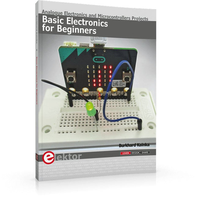
Elektor Publishing Basic Electronics for Beginners
Analogue Electronics and Microcontrollers Projects Hobbyist electronics can be a fun way to learn new skills that can be helpful to your career. Those who understand the basics of electronics can design their own circuits and projects. However, before you run, you need to learn to walk. It all starts with analogue electronics. You should be familiar with the simple components and circuits and understand their basic behaviors and the issues you may encounter. The best way to do this is through real experiments. Theory alone is not enough. This book offers a large number of practical entry-level circuits, with which everyone can gain the basic experience. Through the widespread introduction of microcontrollers, a new chapter in electronics has begun. Microcontrollers are now performing more and more tasks that were originally solved using discrete components and conventional ICs. Starting out has become easier and easier thanks to platforms including Bascom, Arduino, micro:bit. The book introduces numerous manageable microcontroller applications. It’s now a case of less soldering and more programming.
€ 39,95
Members: € 35,96


