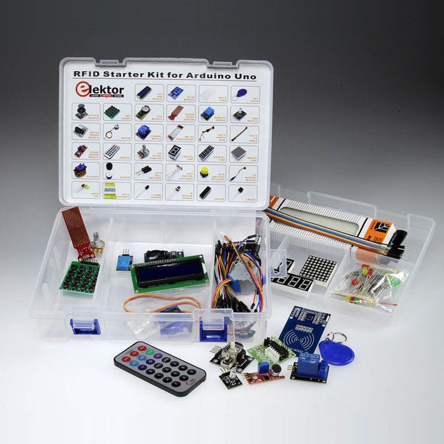
Modern electronic experimenter kits contain modules that just plug together rather than individual components so that now we can quickly get modules talking and then decide in software how the system behaves. Thanks to the wide selection of software library functions we can have a sketch up and running in no time. These kits are worthy successors to the bags of loose components that were a feature of earlier experimenter’s kits. Electronic newbies, practicing engineers and old hands alike are sure to find that these kits interesting. The range of components is sure to get you thinking what you could use them for and they are a good way to build on your existing knowledge. You’ll have no excuse not to go on to design and build your own system! The ‘RFID Starter Kit for Arduino’ comes in a handy case and contains over 30 state-of-the-art components, devices and modules. Although it contains an RFID receiver module along with two RFID tags in the form of a credit card and key fob, the case is an Aladdin’s cave with loads of other useful components. To begin you will need an Arduino Uno along with the starter kit which amongst other things contains: A humidity sensor; A multicolor LED; A large LED-Matrix with 64 LEDs; 4 x 7-segment LED displays; A handheld IR remote controller plus IR receiver chip; A complete LC-Display module with I²C bus interface. The wide range of peripherals included in the kit ensures the number of different experiments and applications you can build. Two example applications that can easily be built using this box of goodies have been described in an article published in Elektor Magazine: Universal weather station with LC-Display and Door entry system using RFID security. More similar projects have been described in the new book Home Automation Projects with Arduino. Kit Contents LCD1602 with I²C RC522 module White card Key chain Joystick module Key board RTC module Water level sensor Humidity sensor RGB module Motor driver module Motor 1 Channel module MB-102 breadboard 65 pcs jumper wire 10 PCS F-M cable Sound sensor module Remote 10 K potentiometer 1 digital tube 4 digital tube Matrix tube 9G servo Buzzer 2 pcs ball switches 3 pcs photoresistance 5 pcs switches with caps 9 V battery with DC 15 pcs LED 30 pcs resistance Flame sensor IR receive sensor 74HC595 LM35DZ Uno R3 board Documentation: Download full description of similar kit.
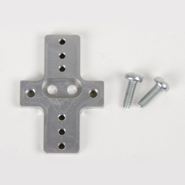
This rigid end effector plate is designed to be in place of the standard AxiDraw pen-lift Z stage, and provides an alternative mounting scheme for mounting various things to the end of the AxiDraw's arm, for applications where greater rigidity is important but the lifting ability of the standard Z stage is not required.
The rigid end effector is custom machined from aluminum, and provides six M3 tapped holes and two M4 tapped holes for mounting what ever it is that you would like to mount to the end of the AxiDraw, to use it as a 2D robot arm. The hole pattern is compatible with the AxiDraw pen clip, so you can, if you like, mount the AxiDraw's pen clip to this end effector.
Installation is straightforward, but requires a Pozidrive PZ2 screwdriver, not included*. Remove the AxiDraw's pen clip, and then remove the pen-lift Z stage by removing two screws with the PZ2 screwdriver. Install the rigid end effector plate in its place, using the two included mounting screws and the PZ2 screwdriver. You may wish to also tie back or fully remove the AxiDraw's cable guides, which normally extend to power the pen-lift stage.
Specifications
Material: Anodized 6061-T6 aluminum
Size: 1.97 x 1.38 x 0.19 inches (50 x 35 x 4.8 mm)
Weight: Approximately 11 g
Mounting hardware: included (Two M4x12 pozidrive-head self-tapping screws)
Compatibility
All AxiDraw V3 family pen plotters
AxiDraw V3/A3
AxiDraw SE/A3
AxiDraw MiniKit models
Highlights
Output Frequency (Sine): 50 MHz
Output Frequency (Square): 15 MHz
Channels: 2
Arbitrary Waveform Length: 16 Mpts
Features
Unique SiFi II (Signal Fidelity II) technology: generate the arbitrary waveforms point by point; recover the signal without distortion; sample rate accurate and adjustable; jitter of all the output waveforms (including Sine, Pulse, etc.) as low as 200 ps
16 Mpts memory depth per channel for arbitrary waveforms
Standard dual-channel with the same performance, equivalent to two independent signal sources
High frequency stability: ±1 ppm; low phase noise: -105 dBc/Hz
Built-in high-order harmonic generator (at most 8-order harmonics)
Built-in 7 digits/s, 240 MHz bandwidth full featured frequency counter
Up to 160 built-in arbitrary waveforms, covering the common signals in engineering application, medical electronics, auto electronics, math processing, and other various fields
Sample rate up to 250 MSa/s, vertical resolution 16 bits
Arbitrary waveform sequence editing function available; arbitrary waveforms also can be generated through the PC software
Various analog and digital modulation functions: AM, FM, PM, ASK, FSK, PSK, and PWM.
Standard waveform combine function, capable of outputting specified waveforms combined with the basic waveforms
Standard channel tracking function, when enabled, all the parameters of both channels are updated based on users' configurations
Standard interface: USB Host&Device and LAN (LXI Core 2011 Device); USB-GPIB function supported
4.3'' TFT
Included
1x Rigol DG2052 Function/Arbitrary Waveform Generator
1x Power cord
1x USB cable
Highlights
Output Frequency (Sine): 70 MHz
Output Frequency (Square): 20 MHz
Channels: 2
Arbitrary Waveform Length: 16 Mpts
Features
Unique SiFi II (Signal Fidelity II) technology: generate the arbitrary waveforms point by point; recover the signal without distortion; sample rate accurate and adjustable; jitter of all the output waveforms (including Sine, Pulse, etc.) as low as 200 ps
16 Mpts memory depth per channel for arbitrary waveforms
Standard dual-channel with the same performance, equivalent to two independent signal sources
High frequency stability: ±1 ppm; low phase noise: -105 dBc/Hz
Built-in high-order harmonic generator (at most 8-order harmonics)
Built-in 7 digits/s, 240 MHz bandwidth full featured frequency counter
Up to 160 built-in arbitrary waveforms, covering the common signals in engineering application, medical electronics, auto electronics, math processing, and other various fields
Sample rate up to 250 MSa/s, vertical resolution 16 bits
Arbitrary waveform sequence editing function available; arbitrary waveforms also can be generated through the PC software
Various analog and digital modulation functions: AM, FM, PM, ASK, FSK, PSK, and PWM.
Standard waveform combine function, capable of outputting specified waveforms combined with the basic waveforms
Standard channel tracking function, when enabled, all the parameters of both channels are updated based on users' configurations
Standard interface: USB Host&Device and LAN (LXI Core 2011 Device); USB-GPIB function supported
4.3'' TFT
Included
1x Rigol DG2072 Function/Arbitrary Waveform Generator
1x Power cord
1x USB cable
Highlights
Output Frequency (Sine): 100 MHz
Output Frequency (Square): 25 MHz
Channels: 2
Arbitrary Waveform Length: 16 Mpts
Features
Unique SiFi II (Signal Fidelity II) technology: generate the arbitrary waveforms point by point; recover the signal without distortion; sample rate accurate and adjustable; jitter of all the output waveforms (including Sine, Pulse, etc.) as low as 200 ps
16 Mpts memory depth per channel for arbitrary waveforms
Standard dual-channel with the same performance, equivalent to two independent signal sources
High frequency stability: ±1 ppm; low phase noise: -105 dBc/Hz
Built-in high-order harmonic generator (at most 8-order harmonics)
Built-in 7 digits/s, 240 MHz bandwidth full featured frequency counter
Up to 160 built-in arbitrary waveforms, covering the common signals in engineering application, medical electronics, auto electronics, math processing, and other various fields
Sample rate up to 250 MSa/s, vertical resolution 16 bits
Arbitrary waveform sequence editing function available; arbitrary waveforms also can be generated through the PC software
Various analog and digital modulation functions: AM, FM, PM, ASK, FSK, PSK, and PWM.
Standard waveform combine function, capable of outputting specified waveforms combined with the basic waveforms
Standard channel tracking function, when enabled, all the parameters of both channels are updated based on users' configurations
Standard interface: USB Host&Device and LAN (LXI Core 2011 Device); USB-GPIB function supported
4.3'' TFT
Included
1x Rigol DG2102 Function/Arbitrary Waveform Generator
1x Power cord
1x USB cable
Specifications
Channels: 3
Total Power: 195 Watts
Max. Voltage: 30 Volts
Max. Current: 3 Amps
Low ripple and noise: <350 μVrms/2 mVpp
Excellent linear regulation rate and load regulation rate
Fast transient response time: <50 μs
Some channels are isolated
Standard OVP/OCP/OTP protection functions
Standard timing output
Built-in V,A,W measurements and waveform display
Independent control for each channel
3.5 inch TFT display
Included
1x Rigol DP832 DC Power Supply
1x Power cord
1x USB cable
Specifications
Bandwidth: 50 MHz
Analog Channels: 4
Real-time sample rate up to 1 GS/s
Memory depth up to 24 Mpts
Up to 30,000 wfms/s waveform capture rate
Up to 60,000 frames hardware real-time waveform recording and playback functions
Innovative 'UltraVision' technology
Various trigger and bus decoding functions
Low noise floor, vertical scale range: 1 mV/div to 10 V/div
Various interfaces: USB Host&Device, LAN (LXI), AUX
Compact size, light weight, easy to use
7 inch WVGA (800x480) TFT LCD, intensity graded color display
Included
1x Rigol DS1054Z Oscilloscope
1x Power cord
1x USB cable
4x PVP2150 Passive oscilloscope probe (150 MHz)
Specifications
Bandwidth: 200 MHz
Analog Channels: 2
Real-time sample rate up to 1 GS/s
Memory depth up to 24 Mpts
Up to 30,000 wfms/s waveform capture rate
Up to 60,000 frames hardware real-time waveform recording and playback functions
Innovative 'UltraVision' technology
Various trigger and bus decoding functions
Low noise floor, vertical scale range: 1 mV/div to 10 V/div
Various interfaces: USB Host&Device, LAN (LXI), AUX
Compact size, light weight, easy to use
7 inch WVGA (800x480) TFT LCD, intensity graded color display
Included
1x Rigol DS1202Z-E Oscilloscope
1x Power cord
1x USB cable
2x PVP2350 passive oscilloscope probe (350 MHz)
With the availability of free and open source C/C++ compilers today, you might wonder why someone would be interested in assembler language. What is so compelling about the RISC-V Instruction Set Architecture (ISA)? How does RISC-V differ from existing architectures? And most importantly, how do we gain experience with the RISC-V without a major investment? Is there affordable hardware available?
The availability of the Espressif ESP32-C3 chip provides a way to get hands-on experience with RISC-V. The open sourced QEMU emulator adds a 64-bit experience in RISC-V under Linux. These are just two ways for the student and enthusiast alike to explore RISC-V in this book.
The projects in this book are boiled down to the barest essentials to keep the assembly language concepts clear and simple. In this manner you will have “aha!” moments rather than puzzling about something difficult. The focus in this book is about learning how to write RISC-V assembly language code without getting bogged down. As you work your way through this tutorial, you’ll build up small demonstration programs to be run and tested. Often the result is some simple printed messages to prove a concept. Once you’ve mastered these basic concepts, you will be well equipped to apply assembly language in larger projects.
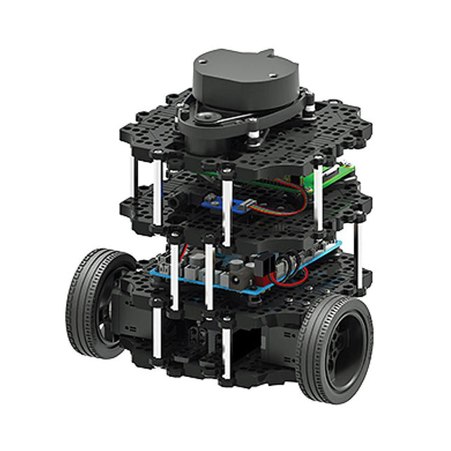
World’s Most Popular ROS Platform TurtleBot is the most popular open source robot for education and research. The new generation TurtleBot3 is a small, low cost, fully programmable, ROS based mobile robot. It is intended to be used for education, research, hobby and product prototyping. Affordable Cost TurtleBot was developed to meet the cost-conscious needs of schools, laboratories and companies. TurtleBot3 is the most affordable robot among the SLAM-able mobile robots equipped with a 360° Laser Distance Sensor LDS-01. Small Size The dimension of TurtleBot3 Burger is only 138 x 178 x 192 mm (L x W x H). Its size is about 1/4 of the size of the predecessor. Imagine keeping TurtleBot3 in your backpack and develop your program and test it anywhere you go. ROS Standard The TurtleBot brand is managed by Open Robotics, which develops and maintains ROS. Nowadays, ROS has become the go-to platform for all the roboticists around the world. TurtleBot can be integrated with existing ROS-based robot components, but TurtleBot3 can be an affordable platform for whom want to get started learning ROS. Extensibility TurtleBot3 encourages users to customize its mechanical structure with some alternative options: open source embedded board (as a control board), computer and sensors. TurtleBot3 Burger is a two-wheeled differential drive type platform but it is able to be structurally and mechanically customized in many ways: Cars, Bikes, Trailers and so on. Extend your ideas beyond imagination with various SBC, sensors and motors on a scalable structure. Modular Actuator for Mobile Robot TurtleBot3 is able to get a precise spatial data by using 2 DYNAMIXEL’s in the wheel joints. DYNAMIXEL XM series can be operated by one of 6 operating modes (XL series: 4 operating modes): Velocity control mode for wheels, Torque control mode or Position control mode for joint, etc. DYNAMIXEL can be used even to make a mobile manipulator which is light but can be precisely controlled with velocity, torque and position control. DYNAMIXEL is a core component that makes TurtleBot3 perfect. It is easy to assemble, maintain, replace and reconfigure. Open Control Board for ROS The control board is open-sourced in hardware wise and in software wise for ROS communication. The open source control board OpenCR1.0 is powerful enough to control not only DYNAMIXEL’s but also ROBOTIS sensors that are frequently being used for basic recognition tasks in cost effective way. Various sensors such as Touch sensor, Infrared sensor, Color sensor and a handful more are available. The OpenCR1.0 has an IMU sensor inside the board so that it can enhance precise control for countless applications. The board has 3.3 V, 5 V, 12 V power supplies to reinforce the available computer device lineups. Strong Sensor Lineups TurtleBot3 Burger uses enhanced 360° LiDAR, 9-Axis Inertial Measurement Unit and precise encoder for your research and development. Open Source The hardware, firmware and software of TurtleBot3 are open source which means that users are welcomed to download, modify and share source codes. All components of TurtleBot3 are manufactured with injection molded plastic to achieve low cost, however, the 3D CAD data is also available for 3D printing. Specifications Maximum translational velocity 0.22 m/s Maximum rotational velocity 2.84 rad/s (162.72 deg/s) Maximum payload 15 kg Size (L x W x H) 138 x 178 x 192 mm Weight (+ SBC + Battery + Sensors) 1 kg Threshold of climbing 10 mm or lower Expected operating time 2h 30m Expected charging time 2h 30m SBC (Single Board Computers) Raspberry Pi 4 (2 GB RAM) MCU 32-bit ARM Cortex-M7 with FPU (216 MHz, 462 DMIPS) Actuator XL430-W250 LDS (Laser Distance Sensor) 360 Laser Distance Sensor LDS-01 or LDS-02
IMU Gyroscope 3 AxisAccelerometer 3 Axis Power connectors 3.3 V/800 mA5 V/4 A12 V/1 A Expansion pins GPIO 18 pinsArduino 32 pin Peripheral 3x UART, 1x CAN, 1x SPI, 1x I²C, 5x ADC, 4x 5-pin OLLO DYNAMIXEL ports 3x RS485, 3x TTL Audio Several programmable beep sequences Programmable LEDs 4x User LED Status LEDs 1x Board status LED1x Arduino LED1x Power LED Buttons and Switches 2x Push buttons, 1x Reset button, 2x Dip switch Battery Lithium polymer 11.1 V 1800 mAh / 19.98 Wh 5C PC connection USB Firmware upgrade via USB / via JTAG Power adapter (SMPS) Input: 100-240 VAC 50/60 Hz, 1.5 A @maxOutput: 12 VDC, 5 A Downloads ROS Robot Programming GitHub E-Manual Community
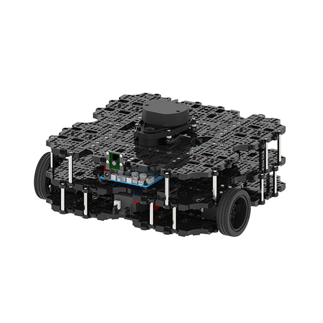
World’s Most Popular ROS Platform TurtleBot is the most popular open source robot for education and research. The new generation TurtleBot3 is a small, low cost, fully programmable, ROS based mobile robot. It is intended to be used for education, research, hobby and product prototyping. Affordable Cost TurtleBot was developed to meet the cost-conscious needs of schools, laboratories and companies. TurtleBot3 is the most affordable robot among the SLAM-able mobile robots equipped with a 360° Laser Distance Sensor LDS-01. ROS Standard The TurtleBot brand is managed by Open Robotics, which develops and maintains ROS. Nowadays, ROS has become the go-to platform for all the roboticists around the world. TurtleBot can be integrated with existing ROS-based robot components, but TurtleBot3 can be an affordable platform for whom want to get started learning ROS. Extensibility TurtleBot3 encourages users to customize its mechanical structure with some alternative options: open source embedded board (as a control board), computer and sensors. TurtleBot3 Waffle Pi is a two-wheeled differential drive type platform but it is able to be structurally and mechanically customized in many ways: Cars, Bikes, Trailers and so on. Extend your ideas beyond imagination with various SBC, sensors and motors on a scalable structure. Modular Actuator for Mobile Robot TurtleBot3 is able to get a precise spatial data by using 2 DYNAMIXEL’s in the wheel joints. DYNAMIXEL XM series can be operated by one of 6 operating modes (XL series: 4 operating modes): Velocity control mode for wheels, Torque control mode or Position control mode for joint, etc. DYNAMIXEL can be used even to make a mobile manipulator which is light but can be precisely controlled with velocity, torque and position control. DYNAMIXEL is a core component that makes TurtleBot3 perfect. It is easy to assemble, maintain, replace and reconfigure. Open Control Board for ROS The control board is open-sourced in hardware wise and in software wise for ROS communication. The open source control board OpenCR1.0 is powerful enough to control not only DYNAMIXEL’s but also ROBOTIS sensors that are frequently being used for basic recognition tasks in cost effective way. Various sensors such as Touch sensor, Infrared sensor, Color sensor and a handful more are available. The OpenCR1.0 has an IMU sensor inside the board so that it can enhance precise control for countless applications. The board has 3.3 V, 5 V, 12 V power supplies to reinforce the available computer device lineups. Open Source The hardware, firmware and software of TurtleBot3 are open source which means that users are welcomed to download, modify and share source codes. All components of TurtleBot3 are manufactured with injection molded plastic to achieve low cost, however, the 3D CAD data is also available for 3D printing. Specifications Maximum translational velocity 0.26 m/s Maximum rotational velocity 1.82 rad/s (104.27 deg/s) Maximum payload 30 kg Size (L x W x H) 281 x 306 x 141 mm Weight (+ SBC + Battery + Sensors) 1.8 kg Threshold of climbing 10 mm or lower Expected operating time 2h Expected charging time 2h 30m SBC (Single Board Computers) Raspberry Pi 4 (2 GB RAM) MCU 32-bit ARM Cortex-M7 with FPU (216 MHz, 462 DMIPS) Remote Controller RC-100B + BT-410 Set (Bluetooth 4, BLE) Actuator XL430-W210 LDS (Laser Distance Sensor) 360 Laser Distance Sensor LDS-01 or LDS-02
Camera Raspberry Pi Camera Module v2.1 IMU Gyroscope 3 AxisAccelerometer 3 Axis Power connectors 3.3 V/800 mA5 V/4 A12 V/1 A Expansion pins GPIO 18 pinsArduino 32 pin Peripheral 3x UART, 1x CAN, 1x SPI, 1x I²C, 5x ADC, 4x 5-pin OLLO DYNAMIXEL ports 3x RS485, 3x TTL Audio Several programmable beep sequences Programmable LEDs 4x User LED Status LEDs 1x Board status LED1x Arduino LED1x Power LED Buttons and Switches 2x Push buttons, 1x Reset button, 2x Dip switch Battery Lithium polymer 11.1 V 1800 mAh / 19.98 Wh 5C PC connection USB Firmware upgrade via USB / via JTAG Power adapter (SMPS) Input: 100-240 VAC 50/60 Hz, 1.5 A @maxOutput: 12 VDC, 5 A Downloads ROS Robot Programming GitHub E-Manual Community
Specifications Operating Voltage: 3.3 V ESP-12E MCU Display Size: 1.28 inch USB Port for Power & Data Transmission Interface Pins: 4 GPIO, 1 GND, 1 Power Driver: GC9A01 Resolution240 x 240 Pixel Color: 65 K RGB Interface: SPI Downloads STEP File Dimensions 3D File Schematic GitHub
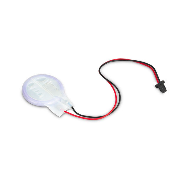
The power-management IC used on Raspberry Pi 5 integrates a real-time clock, and charging circuitry for a button cell which can power the clock while main power is disconnected. This Panasonic ML-2020 lithium manganese dioxide battery with a two-pin plug and a double-sided adhesive pad can be connected directly to the battery connector of the Raspberry Pi 5 and attached to the inside of a case or another convenient location.
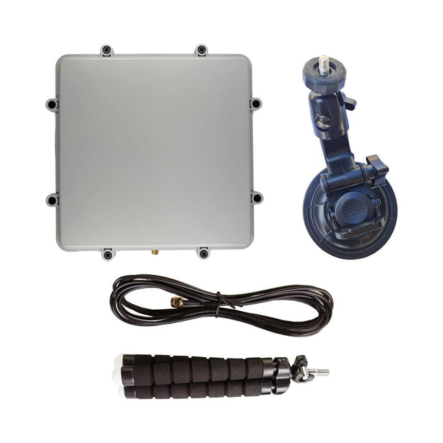
The antenna allows for reception of L-band satellites that transmit between 1525-1660 MHz, such as Inmarsat, Iridium and GPS. Please note it is NOT for receiving weaker signals like HRPT and GOES which require a dish antenna.
The patch comes with useful mounting accessories including a window suction cup, bendable tripod and 3M RG174 coax cable. The patch and active circuitry is enclosed in a weather proof enclosure.
Links
Inmarsat STD-C EGC
AERO Satellite ACARS
AERO C-Channel Voice
Iridium Decoding
GPS and GNSS Experiments
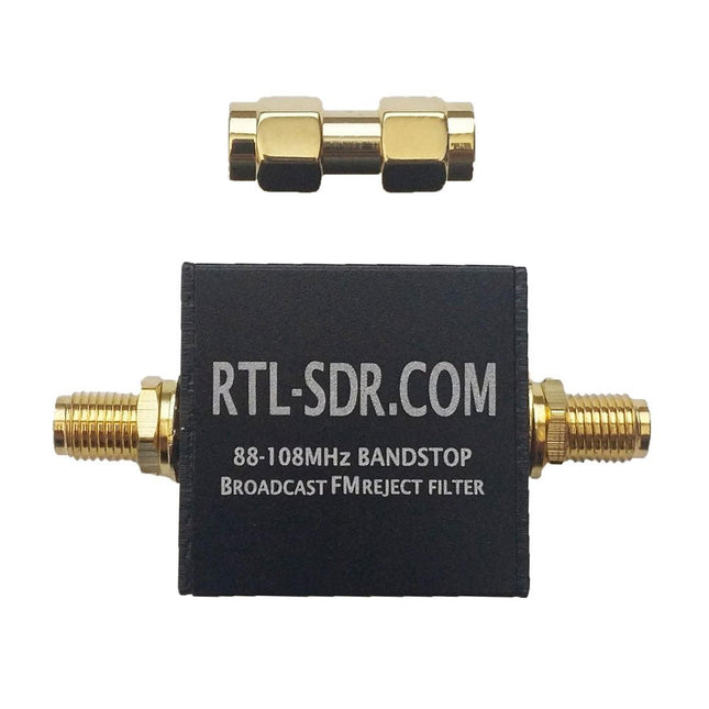
This filter rejects signals between 88-108 MHz with around 50 dB or more attenuation. A broadcast FM band-stop filter is very useful for use with SDRs as in some areas broadcast FM signals can be so strong that they overload the SDR, causing very poor performance in other bands. You can tell if this is the case for you if you see images of BCFM stations or interference that looks like a WFM signal at other frequencies when you turn up the gain.
The filter is based on a simple 7th order Chebyshev design. The 3 dB roll off is at 76 MHz and 122 MHz. 88 MHz is attenuated by almost 60 dB, and 108 MHz is attenuated by 45-50 dB. Outside of the pass band the insertion loss is practically zero below 500 MHz, less than 0.5 dB from 500 MHz – 1 GHz, and below 1.5 dB between 1-2 GHz. Between 2-3 GHz performance degrades slightly, but insertion loss remains below 1.5 dB for most frequencies. The filter can also pass up to 80 mA of DC current (probably can do more) and has negligible DC resistance.
The filter comes in a 28 x 28 x 13 mm aluminum enclosure and uses female SMA connectors on each end. Included in the package is also a SMA male to SMA male straight barrel adapter.
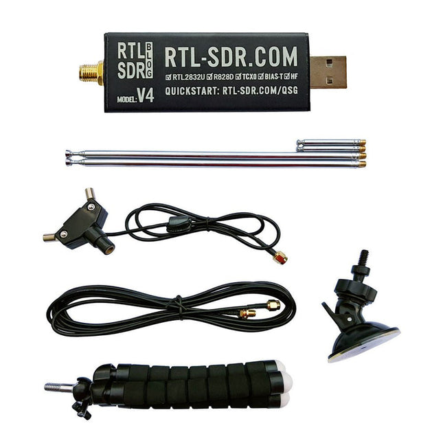
RTL-SDR is an affordable dongle that can be used as a computer-based radio scanner for receiving live radio signals between 500 kHz and 1.75 GHz in your area.
The RTL-SDR V4 offers several improvements over generic brands including use of the R828D tuner chip, triplexed input filter, notch filter, improved component tolerances, a 1 PPM temperature compensated oscillator (TCXO), SMA F connector, aluminium case with passive cooling, bias tee circuit, improved power supply, and a built in HF upconverter.
RTL-SDR V4 comes with the portable dipole antenna kit. It is great for beginners as it allows for terrestrial and satellite reception and easy to mount outdoors and designed for portable and temporary outside usage.
Features
Improved HF reception: V4 now uses a built-in upconverter instead of using a direct sampling circuit. This means no more Nyquist folding of signals around 14.4 MHz, improved sensitivity, and adjustable gain on HF. Like the V3, the lower tuning range remains at 500 kHz and very strong reception may still require front end attenuation/filtering.
Improved filtering: The V4 makes use of the R828D tuner chip, which has three inputs. The SMA input has been triplexed input into 3 bands: HF, VHF and UHF. This provides some isolation between the 3 bands, meaning out of band interference from strong broadcast stations is less likely to cause desensitization or imaging.
Improved filtering x2: In addition to the triplexing, the open drain pin on the R828D can be also used, which allows to add simple notch filters for common interference bands such as broadcast AM, broadcast FM and the DAB bands. These only attenuate by a few dB, but may still help.
Improved phase noise on strong signals: Due to an improved power supply design, phase noise from power supply noise has been significantly reduced.
Less heat: Another advantage of the improved power supply is low power consumption and less heat generation compared to the V3.
Included
1x RTL-SDR V4 dongle (R828D RTL2832U 1PPM TCXO SMA)
2x 23 cm to 1 m telescopic antenna
2x 5 cm to 13 cm telescopic antenna
1x Dipole antenna base with 60 cm RG174
1x 3 m RG174 extension cable
1x Flexible tripod mount
1x Suction cup mount
Downloads
Datasheet
User Guide
Quick Start Guide
SDR# User Guide
Dipole Antenna Guide
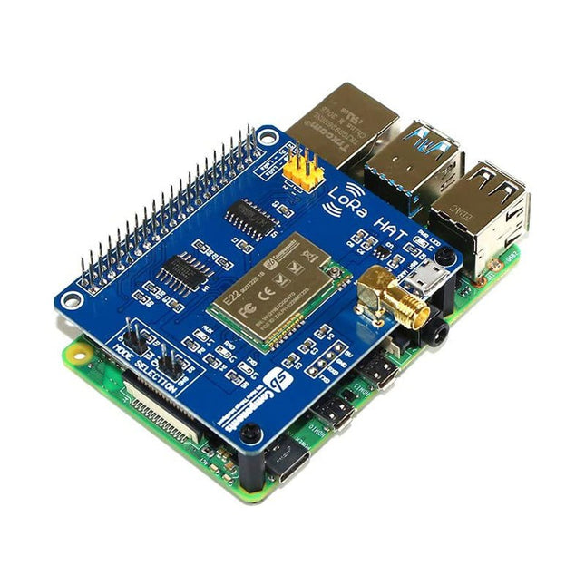
LoRa HAT, a low-power consumption data transmission module, comes with an onboard CH340 USB to UART converter, Voltage Level Translator (74HC125V), E22-900T22S and E22-400T22S SMA antenna connector, IPEX antenna connector, LoRa Spread Spectrum Modulation technology with auto multi-level repeating. Features Onboard 1.14' LCD Voltage Level Translator (74HC125V) Communication range up to 5 km Supports auto repeating to transmit longer Low Power Consumption Highly Secured For Evaluating signal quality with the RSSI or 'Received Signal Strength Indicator' Wireless parameter configuration support Fixed-point transmission support SMA and IPEX Antenna Connector USB to LoRa and Pico to LoRa Communication via UART Comes with development resources and manual LED Indicators: RXD/TXD: UART RX/TX indicator AUX: auxiliary indicator PWR: power indicator Serial/USB selection jumpers: A: USB TO UART to control the LoRa module through USB B: control the LoRa module through Raspberry Pi Pico Data/Command mode selection jumpers: Short M0, short M1: Transmission mode Short M0, open M1: Configuration mode Open M0, short M1: WOR mode Open M0, open M1: Deep sleep mode Specifications Frequency: 850.125~930.125 MHz / 410~493 MHz (Programmable Range) Power: 22dBm Distance: Up to 5 km Interface: UART Communication Serial Port Module: E22-900T22S1B / E22-400T22S Voltage Level Translator: 74HC125V Included 1x LoRa Module
1x Antenna Note: Raspberry Pi Board is not included. Downloads GitHub Wiki
Raspberry Pi Pico Breadboard Kit helps the user to configure GPIO of Raspberry Pi Pico for use with external devices.Raspberry Pi Pico Breadboard Kit is a multi-purpose Kit that consists of a “400 points half-size breadboard” on top, a Programmable Buzzer, 4 programmable LEDs, 4 push buttons, and dedicated 5 V, 3V3, and GND pins at a single place. SB Components developed Raspberry Pi Pico Breadboard Kit with advanced features like independently controllable LEDs, Switches, a 400 points half-size breadboard that helps the user to prototype their projects with Raspberry Pi Pico in an efficient way.Raspberry Pi Pico Breadboard Kit can be interfaced with Raspberry Pi Pico from which a user can run electronics experiments, prototypes, mini robots, games, interact with Linux-ready Raspberry Pi, Exploration of circuits, etc. One can also connect external components with the breadboard provided on the top of the Raspberry Pi Pico Breadboard Kit.Features
Four independent controlled LEDs
Four independent controlled push buttons
Compatible with Pico
A 400 points half size breadboard
Programmable buzzer
Dedicated 5 V, 3V3 and Gnd pins for easy use
Specifications
Operating voltage
3.3 VDC
Communication interface
GPIO
Dimensions
85 x 133 mm
Applications
Electrical experiments
Prototypes
Mini robots
Games
Exploration of circuits
Downloads
Manual
Example codes
Circuit diagram
GitHub
Included
1x Pico Breadboard Kit
5x Male to Male Jumper Wires
5x Female to Female Jumper Wires
5x Male to female Jumper Wires
Note: Raspberry Pi Pico is not included.
Pico Cube is a 4x4x4 LED cube HAT for Raspberry Pi Pico with 5 VDC operating voltage. Pico cube, a monochromatic Green with 64 LEDs, is a fun way to learn programming. It is designed to perform incandescent operations with low energy consumptions, robust outlook, and easy installation that make people/kids/users learn the effects of LED lights with a different pattern of colors via the combination of software and hardware i.e. Raspberry Pi Pico.
Features
Standard 40 Pins Raspberry Pi Pico Header
GPIO Based Communication
64 High-Intensity Monochromatic LEDs
Individual LED access
Each Layer Access
Specifications
Operating Voltage: 5 V
Color: Green
Communication: GPIO
LEDs: 64
Included
1x Pico Cube Base PCB
4x Layer PCB
8x Pillar PCB
2x Male Berg (1 x 20)
2x Female Berg (1 x 20)
70 LEDs
Note: Raspberry Pi Pico is not included.
Downloads
GitHub
Wiki
Pico Cube is a 4x4x4 LED cube HAT for Raspberry Pi Pico with 5 VDC operating voltage. Pico cube, a monochromatic Red with 64 LEDs, is a fun way to learn programming. It is designed to perform incandescent operations with low energy consumptions, robust outlook, and easy installation that make people/kids/users learn the effects of LED lights with a different pattern of colors via the combination of software and hardware i.e. Raspberry Pi Pico.
Features
Standard 40 Pins Raspberry Pi Pico Header
GPIO Based Communication
64 High-Intensity Monochromatic LEDs
Individual LED access
Each Layer Access
Specifications
Operating Voltage: 5 V
Color: Red
Communication: GPIO
LEDs: 64
Included
1x Pico Cube Base PCB
4x Layer PCB
8x Pillar PCB
2x Male Berg (1 x 20)
2x Female Berg (1 x 20)
70 LEDs
Note: Raspberry Pi Pico is not included.
Downloads
GitHub
Wiki
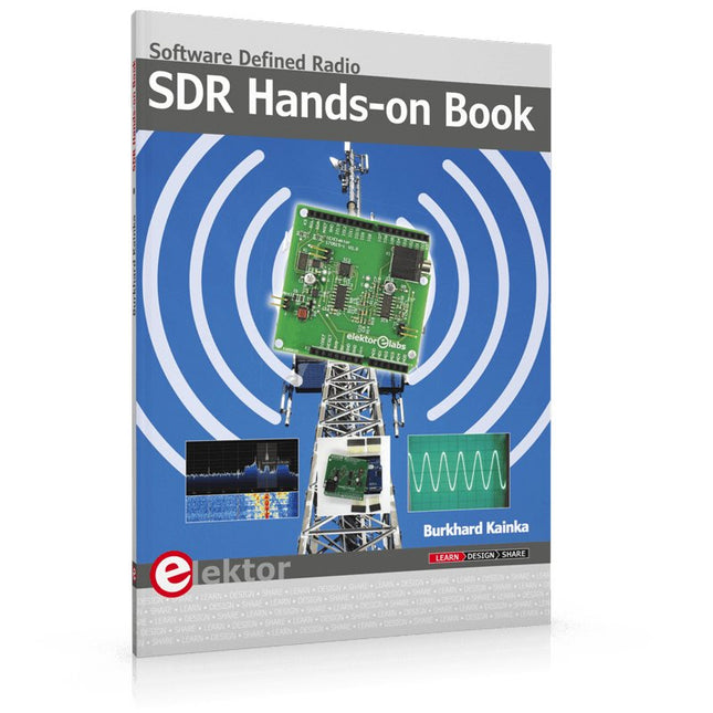
The short-wave technique has a very particular appeal: It can easily bridge long distances. By reflecting short-wave signals off the conductive layers of the ionosphere, they can be received in places beyond the horizon and therefore can reach anywhere on earth. Although technology is striving for ever higher frequencies, and radio is usually listened to on FM, DAB+, satellite or the Internet, modern means of transmission require extensive infrastructure and are extremely vulnerable. In the event of a global power outage, there is nothing more important than the short-wave. Amateur radio is not only a hobby, it’s also an emergency radio system!
Elektor’s SDR-Shield is a versatile shortwave receiver up to 30 MHz. Using an Arduino and the appropriate software, radio stations, morse signals, SSB stations, and digital signals can be received.
In this book, successful author and enthusiastic radio amateur, Burkhard Kainka describes the modern practice of software defined radio using the Elektor SDR Shield. He not only imparts a theoretical background but also explains numerous open source software tools.