Products
-

Elektor Digital SDR Hands-on Book (E-book)
The short-wave technique has a very particular appeal: It can easily bridge long distances. By reflecting short-wave signals off the conductive layers of the ionosphere, they can be received in places beyond the horizon and therefore can reach anywhere on earth. Although technology is striving for ever higher frequencies, and radio is usually listened to on FM, DAB+, satellite or the Internet, modern means of transmission require extensive infrastructure and are extremely vulnerable. In the event of a global power outage, there is nothing more important than the short-wave. Amateur radio is not only a hobby, it’s also an emergency radio system! Elektor’s SDR-Shield is a versatile shortwave receiver up to 30 MHz. Using an Arduino and the appropriate software, radio stations, morse signals, SSB stations, and digital signals can be received. In this book, successful author and enthusiastic radio amateur, Burkhard Kainka describes the modern practice of software defined radio using the Elektor SDR Shield. He not only imparts a theoretical background but also explains numerous open source software tools.
€ 29,95
Members € 23,96
-
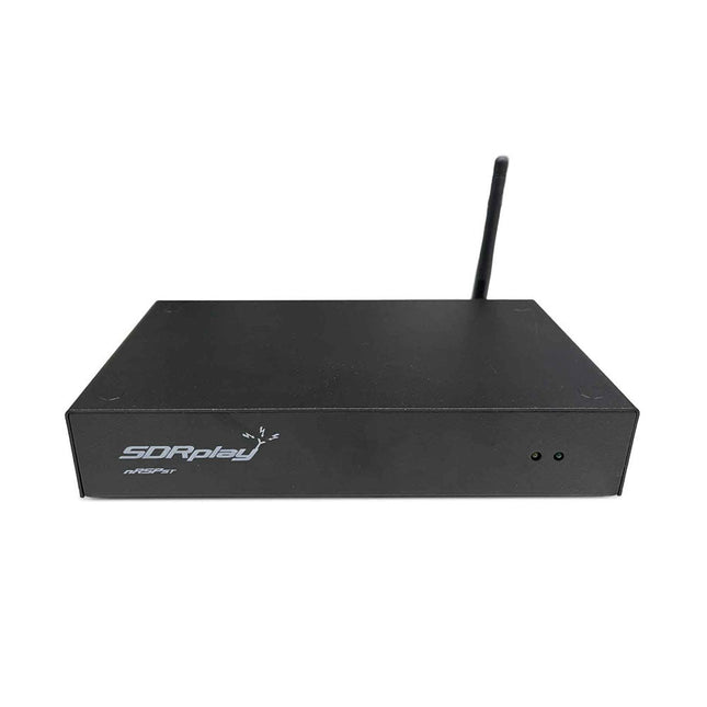
SDRplay SDRplay nRSP-ST Networked Radio Receiver (1 kHz to 2 GHz)
The nRSP-ST is a networked general coverage radio receiver for frequencies from 1 kHz to 2 GHz with up to 10 MHz of spectrum visibility. The nRSP-ST is your own personal remotely accessible SDR which can also be shared with a small number of trusted friends or colleagues. The nRSP-ST addresses the needs of radio enthusiasts who want a 'plug-and-play' solution for remote reception. As well as achieving this, we have addressed typical internet bandwidth limitations with the creation of a novel IQ Lite mode, which efficiently delivers channels of IQ data. We are also introducing the ability to control and store IQ recordings at the remote location. The nRSP-ST is ideal for anyone wanting a wideband remote receiver without needing computer skills and hours of set-up time and ongoing maintenance at the remote location. Features "Plug and play" integrated, networked general coverage receiver: Combines a receiver, a host computer and a whole lot more – all in one box! Apply power and connect to the internet (Ethernet or Wi-Fi) and the nRSP-ST is automatically accessible from anywhere Multi-platform SDRconnectTM software supports local operation or remote access on Windows, MacOS or Linux platforms The nRSP-ST & SDRconnect are configurable for available network bandwidth: In Full IQ mode, the nRSP-ST provides IQ data transfer of the visible spectrum bandwidth (e.g. for high-speed LAN or superfast internet connectivity) In IQ Lite mode, the nRSP-ST provides IQ data of channels up to 192 kHz wide (e.g. for digital decoding by the client) In Compact mode the nRSP-ST provides compressed audio (ideal for slower internet connections) Supports multiple client connections with a simultaneous mixture of connection modes – an admin tool allows you to assign usernames and timeouts to trusted friends or colleagues. All modes support visualization of up to 10 MHz spectrum bandwidth Two remote connection options: Use a remote SDRconnect client or Use the built-in web-server for remote access from any web browsing capable device, including Android/iOS tablets and phones The nRSP-ST offers the ability to record IQ and audio files to a NAS (network attached storage) device if available on the LAN. The 14-bit ADC full featured wideband SDR receiver covers all frequencies from 1 kHz through VLF, LF, MW, HF, VHF, UHF and L-band to 2 GHz, with no gaps Remotely monitor up to 10 MHz of spectrum at a time from a choice of 3 antennas Flash upgradable for future feature enhancements Included 1x nRSP-ST Receiver 1x WLAN antenna 1x Power supply 1x Manual Downloads Release notes Software
-
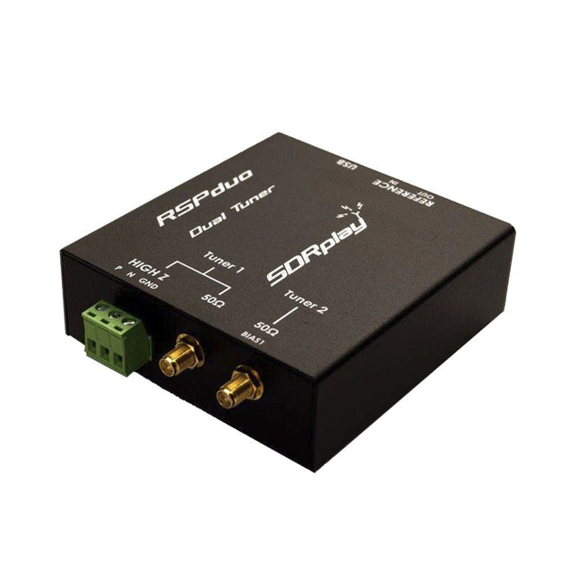
SDRplay SDRplay RSPduo Dual-Tuner 14-bit SDR Receiver (1 kHz to 2 GHz)
The SDRplay RSPduo is a high performance dual-tuner 14-bit SDR receiver. Housed in a high quality steel enclosure, each tuner can operate individually anywhere between 1 kHz and 2 GHz with up to 10 MHz of bandwidth or both tuners can operate simultaneously anywhere between 1 kHz and 2 GHz with up to 2 MHz of bandwidth per tuner. A high stability reference along with external clocking features makes this device ideally suited to industrial, scientific & educational applications. Features Dual tuner provides independent coverage from 1 kHz to 2 GHz using 2 antenna ports simultaneously 14-bit ADC silicon technology Up to 10 MHz visible bandwidth (single tuner mode) or 2 slices of 2 MHz spectrum (dual tuner mode) 3 software-selectable antenna ports (2x 50Ω and 1x 1kΩ high impedance balanced/unbalanced input) High impedance antenna port (1 kHz to 30 MHz) with selectable MW notch filter and choice of 2 pre-selection filters Software selectable AM/FM and DAB broadcast band notch filters for the 2 SMA antenna (1 kHz to 2 GHz) antenna ports External clock input and output enables easy synchronisation to multiple RSPs or external reference clock Powers over the USB cable with a simple type B socket 11 high-selectivity, built in front-end preselection filters on both the 2 SMA antenna ports Software selectable multi-level Low Noise Preamplifier Bias-T power supply for powering antenna-mounted LNA Enclosed in a rugged black painted steel case. SDRuno – World Class SDR software for Windows Documented API for new apps development Specifications Frequency Range 1 kHz – 2 GHz Antenna Connector SMA Antenna Impedance 50 Ohms Current Consumption (Typical) Single Tuner Mode: 180 mA (excl. Bias-T)Dual Tuner Mode: 280 mA (excl. Bias-T) USB Connector USB-B Maximum Input Power +0 dBm Continuous+10 dBm Short Duration ADC Sample Rates 2-10.66 MSPS ADC Number of Bits 14 bit 2-6.048 MSPS12 bit 6.048-8.064 MSPS10 bit 8.064-9.216 MSPS8 bit >9.216 MSPS Bias-T 4.7 V100 mA guaranteed Reference High Temperature Stability (0.5ppm) 24 MHz TCXO.Frequency error trimmable to 0.01ppm in field. Operating Temperature Range −10˚C to +60˚C Dimensions 98 x 94 x 33 mm Weight 315 g Downloads Datasheet Detailed Technical Information Software RSPdx-R2 vs RSPduo RSPdx-R2 RSPduo Continuous coverage from 1 kHz to 2 GHz ✓ ✓ Up to 10 MHz visible bandwidth ✓ ✓ 14-bit ADC silicon technology plus multiple high-performance input filters ✓ ✓ Software selectable AM/FM & DAB broadcast band notch filters ✓ ✓ 4.7 V Bias-T for powering external remote antenna amplifier ✓ ✓ Powers over the USB cable with a simple type B socket ✓ ✓ 50Ω SMA antenna input(s) for 1 kHz to 2 GHz operation (software selectable) 2 2 Additional software selectable Hi-Z input for up to 30 Mhz operation ✓ Additional software selectable 50Ω BNC input for up to 200 MHz operation ✓ Additional LF/VLF filter for below 500 kHz ✓ 24 MHz reference clock input (+ output on RSPduo) ✓ ✓ Dual tuners enabling reception on 2 totally independent 2 MHz ranges ✓ Dual tuners enabling diversity reception using SDRuno ✓ Rugged black painted steel case ✓ ✓ Overall performance below 2 MHz for MW and LF ++ + Multiple simultaneous applications + ++ Performance in challenging fading conditions (*using diversity tuning) + *++
-
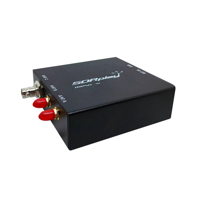
SDRplay SDRplay RSPdx-R2 Single-Tuner 14-bit SDR Receiver (1 kHz to 2 GHz)
The SDRplay RSPdx-R2 is a wideband full featured single-tuner 14-bit SDR receiver which covers the entire RF spectrum from 1 kHz to 2 GHz giving up to 10 MHz of spectrum visibility. It contains three antenna ports, two of which use SMA connectors and operate across the full 1 kHz to 2 GHz range and the third uses a BNC connector which operates up to 200 MHz. The RSPdx-R2 is an enhanced version of the RSPdx with further design improvements for use at frequencies below 2 MHz. Housed in a strong steel case, in addition to the functionality of the RSP1B, the RSPdx-R2 provides three software selectable antenna inputs and an external clock input. It offers excellent performance through HF and VHF frequencies all the way up to 2 GHz. The RSPdx-R2 also supports an "HDR mode" optimised for the demanding radio reception conditions below 2 MHz. The RSPdx-R2, when used in conjunction with SDRplay’s own software, introduces a special HDR (High Dynamic Range) mode for reception within selected bands below 2 MHz. HDR mode delivers improved intermodulation performance and fewer spurious responses for those challenging bands. Features Covers all frequencies from 1 kHz through VLF, LF, MW, HF, VHF, UHF and L-band to 2 GHz, with no gaps Receive, monitor and record up to 10 MHz of spectrum at a time Significantly improved noise performance below 1 MHz (i.e. for some MF, LF and below) Improved dynamic range below 2 MHz both in tuner mode and HDR mode HDR mode below 2 MHz giving overall dynamic range and selectivity advantages Software selectable choice of 3 antenna ports External clock input for synchronisation purposes, or connection to GPS reference clock for extra frequency accuracy Excellent dynamic range for challenging reception conditions Free use of Windows-based SDRuno software (check website for versions supported) Free use of SDRconnect SDR and server software for Windows, MacOS and Linux (Check website for versions supported) Multiplatform driver and API support including Windows, Linux, Mac and Raspberry Pi 4/5 Strong and growing software support network Calibrated S meter/RF power and SNR measurement with SDRuno (including datalogging to .CSV file capability) Documented API provided to allow demodulator or application development on multiple platforms Applications (Amateur) Shortwave radio listening Broadcast DXing (AM/FM/TV) Panadaptor Aircraft (ADS-B and ATC) Slow Scan TV Multi-amateur band monitoring WSPR & digital modes Weather fax (HF and satellite) Satellite monitoring Geostationary environmental satellites Trunked radio Utility and emergency service monitoring Fast and effective antenna comparison Applications (Industrial) Spectrum Analyser Surveillance Wireless microphone monitoring RF surveying IoT receiver chain Signal logging RFI/EMC detection Broadcast integrity monitoring Spectrum monitoring Power measurement Applications (Educational/Scientific) Teaching Receiver design Radio astronomy Passive radar Ionosonde Spectrum analyser Receiver for IoT sensor projects Antenna research Specifications Frequency Range 1 kHz – 2 GHz Antenna Connector SMA Antenna Impedance 50 Ohms Current Consumption (Typical) 190 mA @ >60 MHz (excl. Bias-T)120 mA @ <60 MHz (excl. Bias-T) USB Connector USB-B Maximum Input Power +0 dBm Continuous+10 dBm Short Duration ADC Sample Rates 2-10.66 MSPS ADC Number of Bits 14 bit 2-6.048 MSPS12 bit 6.048-8.064 MSPS10 bit 8.064-9.216 MSPS8 bit >9.216 MSPS Bias-T 4.7 V100 mA guaranteed Reference 0.5ppm 24 MHz TCXOFrequency error trimmable to 0.01ppm in field Operating Temperature −10˚C to +60˚C Dimensions 113 x 94 x 35 mm Weight 315 g Downloads Datasheet Software RSPdx-R2 vs RSPduo RSPdx-R2 RSPduo Continuous coverage from 1 kHz to 2 GHz ✓ ✓ Up to 10 MHz visible bandwidth ✓ ✓ 14-bit ADC silicon technology plus multiple high-performance input filters ✓ ✓ Software selectable AM/FM & DAB broadcast band notch filters ✓ ✓ 4.7 V Bias-T for powering external remote antenna amplifier ✓ ✓ Powers over the USB cable with a simple type B socket ✓ ✓ 50Ω SMA antenna input(s) for 1 kHz to 2 GHz operation (software selectable) 2 2 Additional software selectable Hi-Z input for up to 30 Mhz operation ✓ Additional software selectable 50Ω BNC input for up to 200 MHz operation ✓ Additional LF/VLF filter for below 500 kHz ✓ 24 MHz reference clock input (+ output on RSPduo) ✓ ✓ Dual tuners enabling reception on 2 totally independent 2 MHz ranges ✓ Dual tuners enabling diversity reception using SDRuno ✓ Rugged black painted steel case ✓ ✓ Overall performance below 2 MHz for MW and LF ++ + Multiple simultaneous applications + ++ Performance in challenging fading conditions (*using diversity tuning) + *++
-
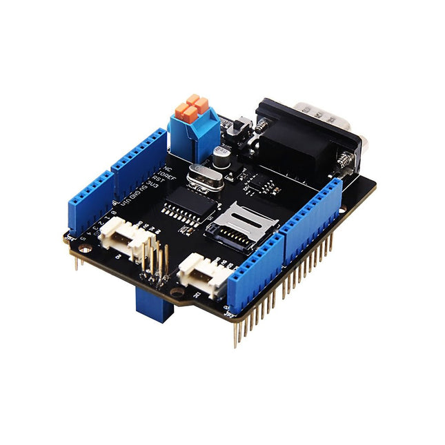
Seeed Studio Seeed Studio CAN-BUS Shield V2 adopts MCP2515 and MCP2551
Features Implements CAN V2.0B at up to 1 Mb/s Industrial standard 9 pin sub-D connector OBD-II and CAN standard pinout selectable. Changeable chip select pin Changeable CS pin for TF card slot Changeable INT pin Screw terminal that easily to connect CAN_H and CAN_L Arduino Uno pin headers Micro SD card holder 2 Grove connectors (I2C and UART) SPI Interface up to 10 MHz Standard (11 bit) and extended (29 bit) data and remote frames Two receive buffers with prioritized message storage
€ 32,95€ 16,50
Members identical
-
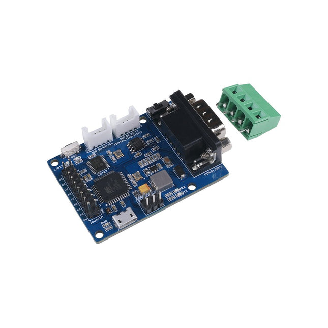
Seeed Studio Seeed Studio CANBed – Arduino CAN-BUS Development Kit
The Seeed Studio CANBed – Arduino CAN-BUS Development Kit integrates an ATmega32U4 microcontroller, eliminating the need for an external Arduino board. It combines an MCP2515 CAN Bus controller and an MCP2551 CAN Bus transceiver on a single board, providing a compact and reliable CAN communication solution. Features ATmega32U4 with Arduino Leonardo bootloader on the board MCP2515 CAN Bus controller and MCP2551 CAN Bus transceiver OBD-II and CAN standard pinout selectable at the sub-D connector Compatible with Arduino IDE Parameter Value MCU ATmega32U4(with Arduino Leonardo bootloader) Clock Speed 16 MHz Flash Memory 32 KB SRAM 2.5 KB EEPROM 1 KB Operate Voltage (CAN-BUS) 9 V - 28 V Operate Voltage (MicroUSB) 5 V Input Interface sub-D Included CANBed PCBA sub-D connector 4PIN Terminal 2x 4PIN 2.0 Connector 1x 9x2 2.54 Header 1x 3x2 2.54 Header
€ 32,95€ 16,50
Members identical
-

Seeed Studio Seeed Studio Deep Learning Starter Kit for Jetson Nano
The starter kit for Jetson Nano is one of the best kits for beginners to get started with Jetson Nano. This kit includes 32 GB MicroSD card, 20 W adapter, 2-pin jumper, camera, and micro-USB cable. Features 32 GB High-performance MicroSD card 5 V 4 A power supply with 2.1 mm DC barrel connector 2-pin jumper Raspberry Pi camera module V2 Micro-B To Type-A USB cable with DATA enabled
€ 64,95€ 32,50
Members identical
-
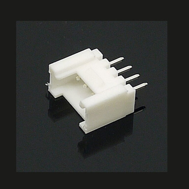
Seeed Studio Seeed Studio Grove 10x Universal 4-pin Connector (2-mm Pitch)
The universal 4 Pin connector is a white 4-pin buckled connector used on Stem, Twigs and Grove cables. The pin spacing is 2 mm. There are 10 connectors per bag. They can be used in DIY projects.
€ 3,95
Members € 3,56
-
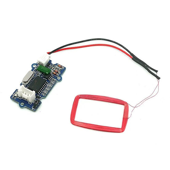
Seeed Studio Seeed Studio Grove 125 kHz RFID Reader
Features Selectable output format: Uart or Wiegand. 4Pins Electronic Brick Interface High Sensitivity Specifications Dimensions: 44 mm x 24 mm x9.6 mm Weight: 15 g Battery: Exclude Voltage: 4.75 V - 5.25 V Working Frequency: 125 kHz Sensing Distance(Max): 70 mm TTL Output: 9600 baud rate, 8 data bits, 1 stop bit, and no verify bit Wiegand Output: 26 bits Wiegand format, 1 even verify bit, 24 data bits, and 1 odd verify bit
€ 17,95
Members € 16,16
-

Seeed Studio Seeed Studio Grove 3-Axis Digital Accelerometer (LIS3DHTR)
Grove 3-Axis Digital Accelerometer (LIS3DHTR) is a low-cost 3-Axis accelerometer in a bundle of Grove products. It is based on the LIS3DHTR chip which provides multiple ranges and interfaces selection. You can never believe that such a tiny 3-Axis accelerometer can support I²C, SPI, and ADC GPIO interfaces, which means you can choose any way to connect with your development board. Besides, this accelerometer can also monitor the surrounding temperature to tune the error caused by it. Features Measurement range: ±2g, ±4g, ±8g, ±16g, multiple ranges selection. Multiple interfaces option: Grove I²C interface, SPI interface, ADC interface. Temperature adjustable: able to adjust and tune the error caused by temperature. 3/5V power supply Specifications Power Supply 3/5V Interfaces IC/SPI/GPIO ADC I²C address Default 0x19, can be changed to 0x18 when connecting SDO Pin with GND ADC GPIO Power input 0-3.3V Interruption An interruption Pin reserved SPI Mode set up Connect the CS Pin with GND Included 1x Grove 3-Axis Digital Accelerometer (LIS3DHTR) 1x Grove cable Downloads LIS3DHTR Datasheet Hardware schematic Arduino Library
€ 7,95
Members € 7,16
-
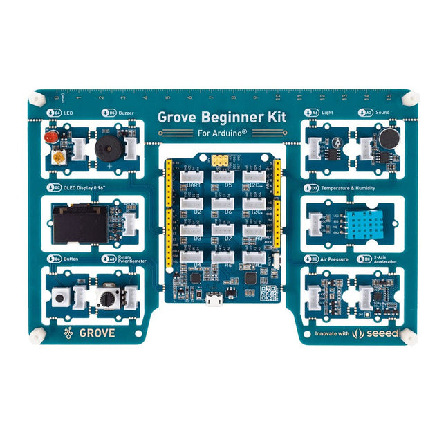
Seeed Studio Seeed Studio Grove Beginner Kit for Arduino
Unlike most kits, the Grove Beginner Kit for Arduino is an all-in-one kit, no breadboard, no soldering, even no wiring is needed. The kit is powered by one Arduino compatible Board (Seeeduino Lotus) together with 10 additional Grove Arduino sensors all in one piece of the board. All the modules have been connected to the Seeeduino(Microcontroller) through the PCB stamp holes so no Grove cables are needed to connect. This is perfect for educational fields where frustrating wiring and soldering are no longer needed. Of course, you can also take the modules out and use Grove cables to connect the modules. You can build any Arduino project you like with this Grove Beginner Kit For Arduino. Included 1x Grove Beginner Kit For Arduino Board 1x Micro USB Cable 6x Grove Cables Included onboard 1x Grove LED 1x Grove Buzzer 1x Grove OLED Display 0.96" 1x Grove Button 1x Grove Rotary Potentiometer 1x Grove Light 1x Grove Sound 1x Grove Temperature & Humidity Sensor 1x Grove Air Pressure Sensor 1x Grove 3-Axis Accelerator 1x Seeeduino Lotus
€ 34,95
Members € 31,46
-
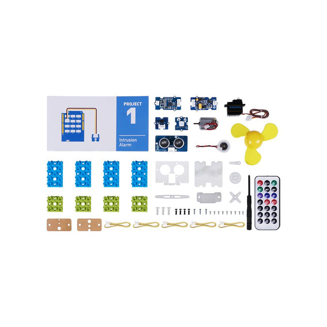
Seeed Studio Seeed Studio Grove Beginner Kit for Arduino (Education Add-on Pack)
This is an add-on kit for the Seeed Studio Grove Beginner Kit for Arduino. Applications Suitable for Arduino beginners Suitable for infrared control and motion detect Suitable for getting started with open-source hardware and Arduino coding Included 1x Grove Water Atomization 1x Grove Mini Fan 1x Grove Servo 1x Grove Ultrasonic Distance Sensor 1x Grove Infrared Receiver 1x Grove Mini PIR Motion Sensor 1x Grove Green Wrapper 1x Grove Blue Wrapper 5x Grove Cable 1x Infrared Remote Control Key 1x Ultrasonic Sensor Bracket Set 1x Motor Bracket Set 1x Servo Base
€ 52,95€ 39,95
Members identical
-
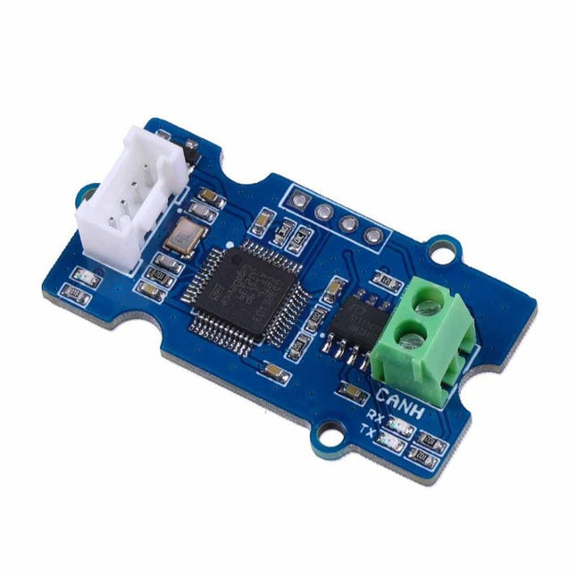
Seeed Studio Seeed Studio Grove CAN-BUS Module (based on GD32E103)
This Grove CAN-BUS Module based on GD32E103 adopts a brand-new design, uses the cost-effective and high-performance GD32E103 microcontroller as the main control and cooperates with a firmware we wrote to complete the function of the serial port to CAN FD. Features Support CAN communication: Implements CAN FD at up to 5 Mb/s Easy to program: Support AT command which enables simple serial port programming Grove ecosystem: 20 x 40 x 10 mm small size, 4-pin Grove connector to plug and play, Arduino compatible This Grove CAN-BUS Module supports CAN FD(CAN with Flexible Data-Rate) communication, which is an extension to the original CAN protocol as specified in ISO 11898-1 that responds to increased bandwidth requirements in automotive networks. In CAN FD, the data rate (i.e. number of bits transmitted per second) is increased to be 5 times faster than the classic CAN (5 Mbit/s for the data payload only, the arbitration bit rate is still limited to 1Mbit/s for compatibility). It supports AT command which enables simple serial port programming. This Grove CAN-BUS Module is based on GD32E103 with a frequency up to 120 MHz. It has a flash size from 64 KB to 128 KB and an SRAM size from 20 KB to 32 KB. Applications Car hacking: allows different parts of the vehicle to talk to each other, including the engine, the transmission, and the brakes. Windows, doors, and mirror adjustment. 3D Printers Building automation Lighting control systems Medical instruments and equipment Specifications MCU GD32E103 UART baud rate Up to 115200 (default 9600) CAN FD baud rate Up to 5 Mb/s Indicator TX and RX led Working voltage 3.3 V Grove connector 4-pin Grove connector to plug and play Size 20 x 40 x 10 mm Downloads Datasheet GitHub
€ 13,95
Members € 12,56
-
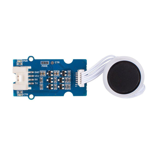
Seeed Studio Seeed Studio Grove Capacitive Fingerprint Scanner/Sensor for Arduino
The Grove Capacitive Fingerprint Scanner/Sensor is based on the KCT203 Semiconductor fingerprint recognition module, including a high-performance MCU, a vertical RF push-type fingerprint sensor, and a touch sensing device. This module features many advantages such as small size, small fingerprint template, low power consumption, high reliability, fast fingerprint recognition, etc. In addition, it is worth mentioning that there is a lovely RGB light around this module to indicate whether the fingerprint recognition is successful. The system is equipped with a high-performance fingerprint algorithm, and the self-learning function is remarkable. After each successful fingerprint recognition, the latest challenge feature values can be integrated into the fingerprint database to continuously improve the fingerprint features, making the experience better. Applications Fingerprint lock devices: door locks, safes, steering wheel locks, padlocks, gun locks, etc. Fingerprint sign-in, access control system Specifications CPU GD32 Fingerprint Template Storage Max. 100 Connector Grove UART Sensor Resolution 508 DPI Sensor Pixel 160x160 False Rejection Rate <1% False Acceptance Rate <0.005% Match Response Time(1:N Mode) <350ms Match Response Time(1:1 Mode) <7ms Sensor Size Φ14.9mm Frame Size Φ 19mm Power Consumption Full speed: ≤40 mA; Sleep: ≤12 uA Operating Voltage 3.3 V / 5 V Operating Temperature -20 ~ 70 ℃ ESD Protection Non-contact 15 KV, contact 8 KV Included 1x KCT203 Semiconductor fingerprint recognition module 1x Sensor cable 1x Grove cable 1x Grove driver board Documentations Grove Capacitive Fingerprint Scanner/Sensor eagle file Grove Capacitive Fingerprint Scanner/Sensor code Wiki
-

Seeed Studio Seeed Studio Grove DHT11 Temperature & Humidity Sensor
The Grove DHT11 Temperature & Humidity Sensor is a high-quality, low-cost digital temperature, and humidity sensor based on the DHT11 module. It is the most common temperature and humidity module for Arduino and Raspberry Pi. It is widely favored by hardware enthusiasts for its many advantages such as low power consumption and excellent long-term stability. Relatively high measurement accuracy can be obtained at a very low cost. The single-bus digital signal is output through the built-in ADC, which saves the I/O resources of the control board. Features Dimensions: 40 x 20 x 8 mm Weight: 10 g Battery: Exclude Input Voltage: 3.3 V & 5 V Measuring Current: 1.3 mA- 2.1 mA Measuring Humidity Range: 5% - 95% RH Measuring Temperature Range: -20 ℃ - 60 ℃
€ 9,95
Members € 8,96
-

Seeed Studio Seeed Studio Grove EMG Detector
Features Grove Compatible 3.5mm Connector 6 Disposable Surface Electrodes Power supply voltage: 3.3V-5V 1000mm Cable Leads No additional power supply Specifications Dimensions: 140 mm x 100 mm x 30 mm Weight: 45 g Battery: Exclude Part List 1 x Grove - EMG Detector 1 x Grove Cable 6 x One-off electrode 1 x DC jacket to button connector cable 1000mm
-

Seeed Studio Seeed Studio Grove GPS Module
Features Supports NMEA and U-Blox 6 protocols. Low power consumption Baud rates configurable Grove UART interface Specifications Dimensions 40 mm x 20 mm x 13 mm Update Rate 1 Hz, max 10 Hz Baud Rate 9,600 – 115,200 Input Voltage 3.3 V / 5 V Navigation Sensitivity -160dBm Power Requirements 3.3/5V Number of Channels 22 tracking, 66 channels Time to first start Cold start: 13s Warm start: 1-2s Hot start: < 1s Antennas Antenna included Accuracy 2.5m GPS Horizontal Position Accuracy
-

Seeed Studio Seeed Studio Grove I²C Thermocouple Amplifier (MCP9600)
Features Integrated Cold-Junction Compensation Supported Types (designated by NIST ITS-90): Type K, J, T, N, S, E, B and R Four Programmable Temperature Alert Outputs: Monitor Hot- or Cold-Junction Temperatures Detect rising or falling temperatures Up to 255°C of Programmable Hysteresis Programmable Digital Filter for Temperature Low Power Dimensions: 20 mm x 40 mm x 18 mm Weight: 18 g Application Petrochemical Thermal Management Hand-Held Measurement Equipment Industrial Equipment Thermal Management Ovens Industrial Engine Thermal Monitor Temperature Detection Racks Downloads Eagle Files Github library Datasheet
€ 22,95
Members € 20,66
-
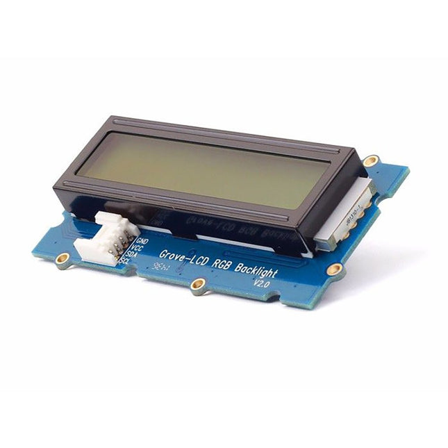
Seeed Studio Seeed Studio Grove LCD RGB Backlight (16x2 full-color Display for Arduino)
With the help of the Grove I²C connector, only 2 signal pins and 2 power pins are needed. You don't even need to care about how to connect these pins. Just plug it into the I²C interface on Seeeduino or Arduino/Raspberry Pi+baseshield via the Grove cable. No complicated wiring, no soldering, no need to worry about burning the LCD caused by the wrong current limiting resistor. Easy peasy. Specifications Battery: Exclude Input Voltage: 5 V Dimensions: 83 x 44 x 13 mm Weight: 42 g
€ 17,95
Members € 16,16
-

Seeed Studio Seeed Studio Grove LED Bar v2.0
Grove LED Bar is comprised of a 10 segment LED gauge bar and an MY9221 LED controlling chip. It can be used as a indicator for remaining battery life, voltage, water level, music volume or other values that require a gradient display. There are 10 LED bars in the LED bar graph: one red, one yellow, one light green, and the rest green. Demo code is available to get you up and running quickly. It lights up the LEDs sequentially from red to green, so the entire bar graph is lit up in the end. Want to go further? Go ahead and code your own effect! Features Each LED segment can be controlled individually via code Grove module Plug-and-play Can be cascaded for a larger display Flexible power option, supports 3-5.5 DC Available demo code Dimensions: 40 x 20 x 18 mm Included 1x Grove LED Bar v2.0 1x Grove Cable Downloads Grove LED Bar Eagle File Grove LED Bar Library MY9221 Datasheet Suli-compatible Library GitHub repository for LED Bar 10 Segment LED Gauge Bar
-

Seeed Studio Seeed Studio Grove Multi-channel Gas Sensor v2
Features Four fully independent sensor elements on one package. The ability to detect a variety of gases, besides Carbon monoxide (CO), Nitrogen dioxide (NO2), Ethyl alcohol(C2H5CH), Volatile Organic Compounds (VOC), etc. Qualitative detecting, rather than quantitative. Compact size for easy deployment. Included 1x Multichannel gas sensor board 1x Grove cable
-

Seeed Studio Seeed Studio Grove Piezo Vibration Sensor
Grove Piezo Vibration Sensor is suitable for measurements of flexibility, vibration, impact and touch. The module is based on PZT film sensor LDT0-028. When the sensor moves back and forth, a certain voltage will be created by the voltage comparator inside of it. Therefore, outputs high & low levels. In spite of the fact that it has a high receptivity for strong impacts, a wide dynamic range (0.001 Hz~1000 MHz) also guarantees excellent measuring performance. Finally, you can adjust its sensitivity by adjusting the potentiometer with a screw. Features Standard grove socket Wide dynamic range:0.001 Hz~1000 MHz Adjustable sensitivity High receptivity for strong impact Applications Vibration Sensing in Washing Machine Low Power Wake-up Switch Low-Cost Vibration Sensing Car Alarms Body Movement Security Systems Downloads Download Wiki PDF Grove - Piezo Vibration Sensor Eagle File Grove - Piezo Vibration Sensor Schematic PDF File Grove - Piezo Vibration Sensor PCB PDF File Piezo Vibration Sensor Datasheet
€ 10,95
Members € 9,86
-

Seeed Studio Seeed Studio Grove PIR Motion Sensor
This Grove - PIR Motion Sensor(Passive Infrared Sensor) can detect infrared signals caused by motion. If the PIR sensor notices the infrared energy, the motion detector is triggered and the sensor outputs HIGH on its SIG pin. The detecting range and response speed can be adjusted by 2 potentiometers soldered on its circuit board, The response speed is from 0.3s - 25s, and max 6 meters of detecting range. The Grove - PIR Motion Sensor(Passive Infrared Sensor) is an easy-to-use motion sensor with Grove compatible interface. Simply connecting it to Base Shield and programming it, it can be used as a suitable motion detector for Arduino projects. For example, the PIR Motion Sensor is commonly used in security alarm systems and automatic lighting applications. Features Grove compatible interface Voltage range: 3 V – 5 V Size: 20 mm x 40 mm Detecting angle: 120 degree Detecting Max distance: 6m (3m by default) Adjustable detecting distance and holding time Applications Motion Sensor Motion Detector Security Alarm System Human Detection System Technical Specifications Dimensions 40 mm x 20 mm x 15 mm Weight 12 g Battery Exclude Voltage range 3 V – 5 V Detecting angle 120 degree Detecting distance max 6m (3m by default)
€ 12,95
Members € 11,66
-

Seeed Studio Seeed Studio Grove Relay
Features Operate voltage: 3.3 V - 5 V Input current: 100mA Rated load: 5 A @ 250 VAC, 5 A @ 30 VDC Contact resistance: 50 mΩ @ 6 VDC 1 A Insulation resistance: 100 MΩ 10 ms Max. Operate time: 10 ms Max. Release time: 5 ms Max. Input interface: Digital Dimensions: 42 mm x 24 mm x 18.5 mm Included 1 x Grove Relay 1 x User Guide Downloads Grove Relay Schematics


