Products
-

Elektor Publishing The ESP32 Cheap Yellow Display Book
Projects Using Arduino IDE and the LVGL Graphics Library The ESP32 is probably one of the most popular microcontrollers used by many people, including students, hobbyists, and professional engineers. Its low cost, coupled with rich features makes it a popular device to use in many projects. Recently, a board called the ESP32 Cheap Yellow Display (CYD for short) is available from its manufacturers. The board includes a standard ESP32 microcontroller together with a 320x240 pixel TFT display. Additionally, the board provides several connectors for interfaces such as GPIO, serial port (TX/RX), power and Ground. The inclusion of a TFT display is a real advantage as it enables users to design complex graphics-based projects without resorting to an external LCD or graphics displays. The book describes the basic hardware of the ESP32 CYD board and provides details of its on-board connectors. Many basic, simple, and intermediate-level projects are given in the book based on the ESP32 CYD, using the highly popular Arduino IDE 2.0 integrated development environment. The use of both the basic graphics functions and the use of the popular LVGL graphics library are discussed in the book and projects are given that use both types of approaches. All the projects given in the book have been tested and are working. The block diagram, circuit diagram, and the complete program listings and program descriptions of all the projects are given with explanations. Readers can use the LVGL graphics library to design highly popular eye-catching full-color graphics projects using widgets such as buttons, labels, calendars, keypads, keyboards, message boxes, spinboxes, sliders, charts, tables, menus, bars, switches, drop-down lists, animations, and many more widgets.
€ 34,95
Members: € 31,46
-
Elektor Digital The ESP32 Cheap Yellow Display Book (PDF)
Projects Using Arduino IDE and the LVGL Graphics Library The ESP32 is probably one of the most popular microcontrollers used by many people, including students, hobbyists, and professional engineers. Its low cost, coupled with rich features makes it a popular device to use in many projects. Recently, a board called the ESP32 Cheap Yellow Display (CYD for short) is available from its manufacturers. The board includes a standard ESP32 microcontroller together with a 320x240 pixel TFT display. Additionally, the board provides several connectors for interfaces such as GPIO, serial port (TX/RX), power and Ground. The inclusion of a TFT display is a real advantage as it enables users to design complex graphics-based projects without resorting to an external LCD or graphics displays. The book describes the basic hardware of the ESP32 CYD board and provides details of its on-board connectors. Many basic, simple, and intermediate-level projects are given in the book based on the ESP32 CYD, using the highly popular Arduino IDE 2.0 integrated development environment. The use of both the basic graphics functions and the use of the popular LVGL graphics library are discussed in the book and projects are given that use both types of approaches. All the projects given in the book have been tested and are working. The block diagram, circuit diagram, and the complete program listings and program descriptions of all the projects are given with explanations. Readers can use the LVGL graphics library to design highly popular eye-catching full-color graphics projects using widgets such as buttons, labels, calendars, keypads, keyboards, message boxes, spinboxes, sliders, charts, tables, menus, bars, switches, drop-down lists, animations, and many more widgets.
€ 29,95
Members: € 26,96
-

Elektor Bundles The ESP32 Cheap Yellow Display Bundle
Over 40 Fully Tested ESP32 Projects Using Arduino IDE and the LVGL Graphics Library This bundle includes the ESP32 Cheap Yellow Display (CYD) – a compact development board combining a standard ESP32 microcontroller with a 320x240 pixel TFT color display. The board also features multiple connectors for GPIO, serial communication (TX/RX), power, and ground. The built-in display is a major advantage, allowing users to create complex, graphics-based projects without the need for external LCDs or displays. The accompanying book introduces the CYD board's hardware and on-board connectors in detail. It provides a range of beginner to intermediate-level projects developed using the popular Arduino IDE 2.0. Both basic graphics functions and the powerful LVGL graphics library are covered, with practical projects illustrating each approach. All included projects have been fully tested and are ready to use. The book provides block diagrams, circuit schematics, complete code listings, and step-by-step explanations. With the LVGL library, readers can create modern, full-color graphical interfaces using widgets such as buttons, labels, sliders, calendars, keyboards, charts, tables, menus, animations, and more. ESP32 Cheap Yellow Display Board This development board (also known as "Cheap Yellow Display") is powered by the ESP-WROOM-32, a dual-core MCU with integrated Wi-Fi and Bluetooth capabilities. It operates at a main frequency of up to 240 MHz, with 520 KB SRAM, 448 KBROM, and a 4 MB Flash memory. The board features a 2.8-inch display with a resolution of 240x320 and resistive touch. Furthermore, the board includes a backlight control circuit, touch control circuit, speaker drive circuit, photosensitive circuit, and RGB-LED control circuit. It also provides a TF card slot, serial interface, DHT11 temperature and humidity sensor interface, and additional IO ports. The module supports development in Arduino IDE, ESP-IDE, MicroPython, and Mixly. Applications Image transmission for Smart Home device Wireless monitoring Smart agriculture QR wireless recognition Wireless positioning system signal And other IoT applications Specifications Microcontroller ESP-WROOM-32 (Dual-core MCU with integrated Wi-Fi and Bluetooth) Frequency Up to 240 MHz (computing power is up to 600 DMIPS) SRAM 520 KB ROM 448 KB Flash 4 MB Operating voltage 5 V Power consumption approx. 115 mA Display 2.8-inch color TFT screen (240 x 320) Touch Resistive Touch Driver chip ILI9341 Dimensions 50 x 86 mm Weight 50 g Downloads GitHub This bundle contains: The ESP32 Cheap Yellow Display Book (normal price: €35) ESP32 Cheap Yellow Display Board (normal price: €25) 1x ESP32 Dev Board with 2.8" Display and acrylic Shell 1x Touch pen 1x Connector cable 1x USB cable
€ 59,95€ 49,95
Best Price
-
Würth The LTspice XVII Simulator (E-book)
Commands and Applications With more than 20 million users worldwide, LTspice XVII is the industry’s definitive electronic simulation software. The pure power, speed and accuracy of its simulations and its robustness make it an irreplaceable tool. This book is both an exhaustive operating manual for the latest version and an invaluable collection of examples and procedures with nearly 700 illustrations, covering everything from initially getting to grips with LTspice XVII to its exact application and extensive use. It will probably answer every question that’s likely to arise during training. All commands and definitions are detailed and classified by topic to make referencing the LTSpice XVII knowledge fast and easy.
€ 44,99
Members: € 40,49
-

Raspberry Pi Foundation The Official Raspberry Pi Handbook 2025
Dive into the world of Raspberry Pi with this huge book of tutorials, project showcases, guides, product reviews, and much more from the writers of The MagPi, the official Raspberry Pi magazine. Raspberry Pi Pico 2 joins Raspberry Pi 5 in this, The Official Raspberry Pi Handbook 2025. Pico 2 comes with a faster processor than the original Pico, and uses less power – while still maintaining the same form factor and pinout. With both Pico 2 and Raspberry Pi 5 you can power any project you can imagine. With 200 pages packed full of maker goodness, you’ll also find inspiration for your Raspberry Pi Zero 2 W, Raspberry Pi 4, or any other Raspberry Pi model you have – there’s something for everyone. In this handbook you’ll find: A get started guide that covers every Raspberry Pi Everything you need to know about the brand-new Raspberry Pi Pico 2 Inspiring projects to spark your next build idea Tutorials for makers of all skill levels Guides for media centres, game emulators, and more! Raspberry Pi Pico 2 Microcontroller not included This bumper book is your definitive guide to everything Raspberry Pi. It’s essential for any maker with big dreams and a thirst for knowledge.
-
Elektor Digital The Raspberry Pi Zero 2 W GO! Book (PDF)
A Fast-Lane Ride From Concept to Project The core of the book explains the use of the Raspberry Pi Zero 2 W running the Python programming language, always in simple terms and backed by many tested and working example projects. On part of the reader, familiarity with the Python programming language and some experience with one of the Raspberry Pi computers will prove helpful. Although previous electronics experience is not required, some knowledge of basic electronics is beneficial, especially when venturing out to modify the projects for your own applications. Over 30 tested and working hardware-based projects are given in the book, covering the use of Wi-Fi, communication with smartphones and with a Raspberry Pi Pico W computer. Additionally, there are Bluetooth projects including elementary communication with smartphones and with the popular Arduino Uno. Both Wi-Fi and Bluetooth are key features of the Raspberry Pi Zero 2 W. Some of the topics covered in the book are: Raspberry Pi OS installation on an SD card Python program creation and execution on the Raspberry Pi Zero 2 W Software-only examples of Python running on the Raspberry Pi Zero 2 W Hardware-based projects including LCD and Sense HAT interfacing UDP and TCP Wi-Fi based projects for smartphone communication UDP-based project for Raspberry Pi Pico W communication Flask-based webserver project Cloud storage of captured temperature, humidity, and pressure data TFT projects Node-RED projects Interfacing to Alexa MQTT projects Bluetooth-based projects for smartphone and Arduino Uno communications
€ 32,95
Members: € 29,66
-
Elektor Digital The State of Hollow State Audio (E-book)
The State of Hollow State Audio in the Second Decade of the 21st Century Vacuum-tube (or valve, depending upon which side of the pond you live on) technology spawned the Age of Electronics early in the 20th Century. Until the advent of solid-state electronics near mid-century, hollow-state devices were the only choice. But following the invention of the transistor (after their process fell to reasonable levels), within a couple of decades, the death of vacuum tubes was widely heralded. Yet here we are some five decades later, and hollow-state equipment is enjoying something of a comeback, especially in the music and high-end audio industries. Many issues surround hollow-state audio: Does it produce—as some claim—better sound? If so, is there science to back up these claims? How do hollow-state circuits work? How do you design hollow-state audio circuits? If hollow-state equipment fails, how do you go about troubleshooting and repairing it? Can we recreate some of the classic hollow-state audio devices for modern listening rooms and recording studios? How can we intelligently modify hollow-state amplifiers to our taste? These and other topics are covered in The State of Hollow State Audio.
€ 32,95
Members: € 29,66
-
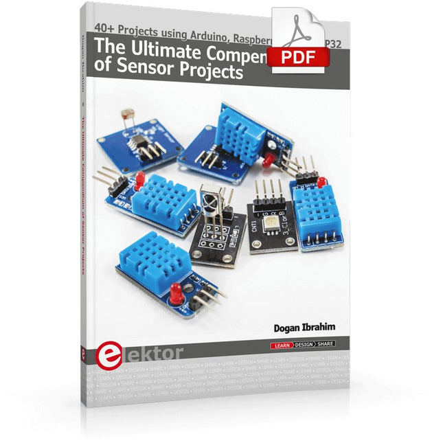
Elektor Digital The Ultimate Compendium of Sensor Projects (E-book)
40+ Projects using Arduino, Raspberry Pi and ESP32 This book is about developing projects using the sensor-modules with Arduino Uno, Raspberry Pi and ESP32 microcontroller development systems. More than 40 different sensors types are used in various projects in the book. The book explains in simple terms and with tested and fully working example projects, how to use the sensors in your project. The projects provided in the book include the following: Changing LED brightness RGB LEDs Creating rainbow colours Magic wand Silent door alarm Dark sensor with relay Secret key Magic light cup Decoding commercial IR handsets Controlling TV channels with IT sensors Target shooting detector Shock time duration measurement Ultrasonic reverse parking Toggle lights by clapping hands Playing melody Measuring magnetic field strength Joystick musical instrument Line tracking Displaying temperature Temperature ON/OFF control Mobile phone-based Wi-Fi projects Mobile phone-based Bluetooth projects Sending data to the Cloud The projects have been organized with increasing levels of difficulty. Readers are encouraged to tackle the projects in the order given. A specially prepared sensor kit is available from Elektor. With the help of this hardware, it should be easy and fun to build the projects in this book.
€ 34,95
Members: € 31,46
-

tinySA tinySA Ultra+ ZS407 Spectrum Analyzer
The tinySA Ultra+ ZS-407 is a compact, handheld spectrum analyzer and signal generator. Covering 100 kHz to 7.3 GHz in Ultra mode, it lets you visualize and analyze RF signals from HF right through many modern wireless bands – and can even spot signals up to ~12 GHz thanks to harmonic tracking. The intuitive 4-inch resistive touchscreen and rechargeable battery make it great for fieldwork, while features like a built-in signal generator, switchable bandpass filters, step attenuator, USB-PC control and auto-calibration add serious versatility. Features Screen size: 4 inch (480 x 320) Spectrum Analyzer for 0.1-900 MHz or, with Ultra mode enabled up to 7.3 GHz, level calibrated up to 7.3 GHz. Can observe signals up to 12 GHz Signal Generator with sine wave output between 0.1-900 MHz or square wave up to 6.3 GHz or RF test signal output up to 7.3 GHz when not used as Spectrum Analyzer. Switchable resolution bandpass filters from 200 Hz to 850 kHz Built-in 20 dB optional LNA Color display showing max 450 points providing gapless covering up to the full frequency range. MicroSD card slot for storing measurements, settings and screen captures. Specifications (Spectrum Analyzer) Input frequency range from 100 kHz to 900 MHz in normal mode and up to 7.3 GHz with ULTRA mode enabled Input impedance 50 ohm when input attenuation set to 10 dB or more. Selectable manual and automatic input attenuation between 0 dB and 31 dB in 1 dB steps when LNA not active Maximum +/-5V DC input Absolute maximum input level of +6 dBm with 0 dB internal attenuation Absolute maximum short term peak input power of +20 dBm with 30 dB internal attenuation Suggested maximum input power of +0 dBm with internal attenuation in automatic mode For best measurements keep input power below -25 dBm Input Intercept Point of third order modulation products (IIP3) of +15 dBm with 0 dB internal attenuation 1 dB compression point at -1 dBm with 0 dB internal attenuation Power detector resolution of 0.5 dB and linearity versus frequency of ±2 dB below 5.3 GHz, ±5dB between 5.3 GHz and 6 GHz Minimum burst length for correct level measurement at 850 kHz RBW in zero span mode of 50 microseconds Absolute power level accuracy after power level calibration of ±2 dB Built-in optional 20 dB LNA with Noise Figure of 5 dB up to 6 GHz Lowest discernible signal without LNA at 30 MHz using a resolution bandwidth of 30 kHz of -102 dBm Lowest discernible signal with LNA at 30 MHz using a resolution bandwidth of 200 Hz of -145 dBm Frequency accuracy equal to the selected resolution bandwidth Phase noise at 30 MHz of -108 dB/Hz at 100 kHz offset and -115 dB/Hz at 1MHz offset Spur free dynamic range when using a 30 kHz resolution bandwidth of 70 dB Resolution filters with a width of 0.2, 1, 3, 10, 30, 100, 300, 600 and 850 kHz On screen resolution of 51, 101, 145, 290 or 450 measurement points. Scanning speed of over 1000 points/second using largest resolution filters. Automatic optimization of actual scanning points to ensure coverage of the whole scan range regardless of the chosen resolution bandwidth Spur suppression option for assessing if certain signals are internally generated or actually present in the input signal Headphone output for listening to the demodulated audio (AM only). Stereo connector with or without microphone, high impedance is louder, short protected Specifications (Signal Generator) Sine wave output with harmonics below -40 dB of fundamental from 100 kHz to 900 MHz Output level selectable in 1 dB steps between -115 dBm and -19 dBm Above 800 MHz choice of two output modes: Cleanest signal mode: square wave, up to 6 GHz with coarse frequency steps and less accurate output level Highest accuracy mode: reduced harmonics with possibly strong spurs up to 7.3 GHz with frequency resolution equal to below 800 MHz and fine output level steps Level accuracy ±2 dB up to 800 MHz between -72 dBm and -19 dBm, less accuracy below -72 dBm, even less accuracy below -110 dBm Output frequency resolution 57.2 Hz Optional AM or FM modulation frequencies between 50 Hz and 5 kHz (AM) or 1 kHz (FM) or sweep over selectable frequency span AM modulation depth between 10% and 100% FM deviation between 1 kHz and 300 kHz Optional output level sweep over maximum the entire output level range Included 1x tinySA Ultra+ ZS407 Spectrum Analyzer 2x SMA connection cables 1x Barrel connector 1x Antenna with SMA connector 1x USB-C cable 1x microSD card (32 GB) Downloads Wiki
€ 196,02
-
Würth Trilogy of Connectors, 3rd Edition (E-book)
Contents Basic principles A connector is an electromechanical system that provides a separable connection between two subsystems of an electronic device without an unacceptable effect on the performance of the device. It will be shown that there are a lot of complex parameters to handle properly to make this statement true. Design / Selection / Assembly This chapter provides an overview of design and material requirements for contact finishes, contact springs and connector housings as well as the major degradation mechanisms for these connector components. To complete this chapter, material selection criteria for each will also be reviewed. Additionally the Level of Interconnection (LOI) was integrated into this chapter as it addresses, where the connector is used within an electronic system and therefore influences the requirements and durability of the connector depending on its use. Applications This chapter is heading to the practical work and shows how customers use connectors in their applications to offer some possibilities and to ease your daily work. Additionally it contains some special topics like tin-whisker or impedance of ZIF cable to offer you extended background knowledge.
€ 26,99
Members: € 24,29
-

Würth Trilogy of Magnetics, 5th Edition (E-book)
Design Guide for EMI Filter Design, SMPS & RF Circuits The book focuses on the selection of components, circuitry and layout recommendations for a wide array of magnetics components, always keeping in mind an EMC point of view. Contents Basic principles The most important laws and foundations of inductive components, equivalent circuit diagrams and simulation models give the reader a basic knowledge of electronics. Components This chapter introduces inductive components and their special properties and areas of use. All relevant components are explained, from EMC components and inductors to transformers, RF components, circuit protection components, shielding materials and capacitors. Applications In this chapter, the reader will find a comprehensive overview of the principle of filter circuits, circuitry and numerous industrial applications that are explained in detail based on original examples.
€ 44,99
Members: € 40,49
-

Elektor Publishing Tube Amplifier Circuits
From SRPP and Mu-Follower to OTL Designs Tube amplifiers suffer from distortion. Fortunately, circuits such as the SRPP amplifier, mu-follower, and beta-follower produce minimal distortion even at output voltages of 50 to 100 Vpeak. These designs are often published with errors. Without a sound understanding of the theory, it is easy to arrive at a flawed design. In the first section of this book, we investigate the origin of distortion, while in the second we investigate the design of and SRPP and a mu-follower. On the internet we can find the most exotic designs. Evaluating them teaches us that these designs often make matters worse rather than better. In the chapter on incorrect SRPPs and mu-followers, we sometimes see bizarre and misguided designs where using a simple single-triode amplifier would perform much better. Push-pull output stages also exist. A great number of them are examined, and their similarity to the SRPP is discussed. This is done especially with the help of the theory behind the OTL based on the ‘mother’ of all OTLs, the Philips HF303. Finally, attention is given to frequency characteristics and technical matters such as the supply voltage and the filament power supply. To illustrate these points, there are a few designs covering the subjects discussed. This book presents much new theory that has not been published before. It is often an eye-opener, showing that many things have a beautiful and unexpected simplicity.
€ 44,95
Members: € 40,46
-

Elektor Digital Tube Amplifier Circuits (E-book)
From SRPP and Mu-Follower to OTL Designs Tube amplifiers suffer from distortion. Fortunately, circuits such as the SRPP amplifier, mu-follower, and beta-follower produce minimal distortion even at output voltages of 50 to 100 Vpeak. These designs are often published with errors. Without a sound understanding of the theory, it is easy to arrive at a flawed design. In the first section of this book, we investigate the origin of distortion, while in the second we investigate the design of and SRPP and a mu-follower. On the internet we can find the most exotic designs. Evaluating them teaches us that these designs often make matters worse rather than better. In the chapter on incorrect SRPPs and mu-followers, we sometimes see bizarre and misguided designs where using a simple single-triode amplifier would perform much better. Push-pull output stages also exist. A great number of them are examined, and their similarity to the SRPP is discussed. This is done especially with the help of the theory behind the OTL based on the ‘mother’ of all OTLs, the Philips HF303. Finally, attention is given to frequency characteristics and technical matters such as the supply voltage and the filament power supply. To illustrate these points, there are a few designs covering the subjects discussed. This book presents much new theory that has not been published before. It is often an eye-opener, showing that many things have a beautiful and unexpected simplicity.
€ 34,95
Members: € 31,46
-
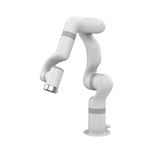
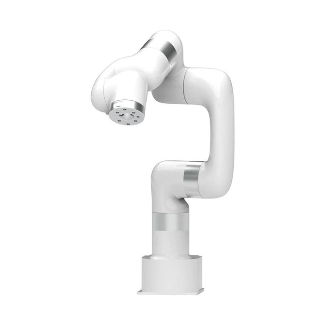
UFactory UFactory 850 Robotic Arm
UFactory 850 is the most powerful robot with industrial grade performance. Features 6DoF Payload: 5 kg Reach: 850 mm Repeatability: 0.02 mm Weight: 20 kg Applications Glambot Welding Screwdriving Robot Vision Industrial Production Designed for both mobile platforms and your workbench The AC control box contains an AC-DC adapter inside, 100-240 V AC is all ready to go. The DC control box supports 48-72 V wide inputs, it perfectly fits the battery system on your mobile platform. Flexible Deployment With Safe Feature Hand teaching, space-saving and easy to re-deploy to multiple applications without changing your production layout. Perfectly for recurrent tasks. Collision detection is available for all of our cobots. Your safety is always the top priority. Graphical Interface For Beginner-Friendly Programming Compatible with various operation systems, including macOS and Windows. Web-based technology compatible with all major browsers. Drag and drop to create your code in minutes. Powerful And Open Source SDK At Your Fingertips Fully functional open-source Python/C++ SDK provides more flexible programming. ROS/ROS2 packages are ready-to-go. Example codes help you to deploy the robotic arm smoothly. Specifications UFactory 850 xArm 5 xArm 6 xArm 7 Payload 5 kg 3 kg 5 kg 3.5 kg Reach 850 mm 700 mm 700 mm 700 mm Degrees of freedom 6 5 6 7 Repeatability ±0.02 mm ±0.1 mm ±0.1 mm ±0.1 mm Maximum Speed 1 m/s 1 m/s 1 m/s 1 m/s Weight (robot arm only) 20 kg 11.2 kg 12.2 kg 13.7 kg Maximum Speed 180°/s 180°/s 180°/s 180°/s Joint 1 ±360° ±360° ±360° ±360° Joint 2 -132°~132° -118°~120° -118°~120° -118°~120° Joint 3 -242°~3.5° -225°~11° -225°~11° ±360° Joint 4 ±360° -97°~180° ±360° -11°~225° Joint 5 -124°~124° ±360° -97°~180° ±360° Joint 6 ±360° ±360° -97°~180° Joint 7 ±360° Hardware Ambient Temperature Range 0-50°C Power Consumption Typical 240 W, max 1000 W Input Power Supply 48 V DC, 20.8 A Footprint Ø 190 mm Materials Aluminum, Carbon Fiber Base Connector Type M8x4 ISO Class Cleanroom 5 Robot Mounting Any End Effector Communication Protocol Modbus RTU End Effector I/O 2x DI / 2x DO / 2x AI / 1x RS485 Communication Mode Ethernet Included 1x UFactory 850 robotic arm 1x AC control box 1x Control box power cable
€ 11.779,00
Best Price
-
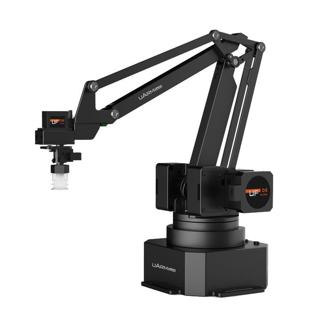
UFactory UFactory uArm Swift Pro
The uArm Swift Pro is a high quality robotic arm that can be used in a wide range of applications. The uArm Swift Pro was developed and optimized for use in education, which means that many packages are already available for open source platforms such as ROS. The uArm Swift Pro has a position repeatability of 0.2 mm and is also equipped with a stepper motor and a 12-bit encoder. These are just a few reasons that make the uArm Swift Pro an excellent choice for educational use. Another great feature is the 3D printing kit that converts the uArm Swift Pro into a 3D printer in less than 1 minute. The uArm supports the following development platforms/systems: UFACTORY SDK Arduino Python ROS GRABCAD OpenMV Smartphone App The smartphone app for iOS is already available in the App Store and enables easy control and monitoring of the robotic arm. The app for Android is in development and will be available soon. An example of the Machine Vision The following GIF shows the uArm in combination with the OpenMV Machine Vision Cam M7 and the facial recognition applications that can be implemented in MicroPython. Specifications Degrees of Freedom: 4 Repeatability: Up to 0.2 mm Payload: 500 g Working Range: 50-320 mm Positioning Speed: 100 m/s Position Feedback: 12-bit Encoder Dimensions: 150 x 140 x 281mm Weight: 2.2 kg Included UFactory uArm Swift Pro Body Bluetooth & Vacuum Gripper Downloads Datasheet
€ 939,00
Best Price
-

UFactory UFactory xArm 5 Lite
A multi-axis robot perfectly balances power and size Features 5 Axis Payload: 3 kg Reach: 700 mm Repeatability: 0.1 mm Max Speed 1000 mm/s Applications Machine Tending Bin Picking Mobile platform Lab Automation Robotic Research Durable Collaborative robots for your automation Industrial-grade harmonic drive and servomotors guarantee 24/7 working without stop. Crafted from Carbon fiber, 15 kg weight makes it possible for easier deployment. Flexible deployment with safe feature Hand teaching, lightweight, space-saving and easy to re-deploy to multiple applications without changing your production layout. Perfectly for recurrent tasks. Collision detection is available for all of our cobots. Your safety is always the top priority. Graphical interface for beginner-friendly programming Compatible with various of operation systems, including macOS and Windows. Web-based technology compatible with all major browsers. Drag and drop to create your code in minutes. Powerful and open source SDK at your fingertips Fully functional open-source Python/C++ SDK provides more flexible programming. ROS/ROS2 packages are ready-to-go. Example codes help you to deploy the robotic arm smoothly. Specifications UFactory 850 xArm 5 xArm 6 xArm 7 Payload 5 kg 3 kg 5 kg 3.5 kg Reach 850 mm 700 mm 700 mm 700 mm Degrees of freedom 6 5 6 7 Repeatability ±0.02 mm ±0.1 mm ±0.1 mm ±0.1 mm Maximum Speed 1 m/s 1 m/s 1 m/s 1 m/s Weight (robot arm only) 20 kg 11.2 kg 12.2 kg 13.7 kg Maximum Speed 180°/s 180°/s 180°/s 180°/s Joint 1 ±360° ±360° ±360° ±360° Joint 2 -132°~132° -118°~120° -118°~120° -118°~120° Joint 3 -242°~3.5° -225°~11° -225°~11° ±360° Joint 4 ±360° -97°~180° ±360° -11°~225° Joint 5 -124°~124° ±360° -97°~180° ±360° Joint 6 ±360° ±360° -97°~180° Joint 7 ±360° Hardware Ambient Temperature Range 0-50°C Power Consumption Min 8.4 W, Typical 200 W, max 400 W Input Power Supply 24 V DC, 16.5 A Footprint Ø 126 mm Materials Aluminum, Carbon Fiber Base Connector Type M5x5 ISO Class Cleanroom 5 Robot Mounting Any End Effector Communication Protocol Modbus RTU(rs485) End Effector I/O 2x DI/2x DO/2x AI/1x RS485 Communication Mode Ethernet Included 1x xArm 5 robotic arm 1x AC control box 1x Robotic arm power cable 1x Robotic arm end effector adapter cable 1x Robotic arm signal cable 1x Control box power cable 1x Network cable 1x Mounting tool 1x Quick start guide
€ 7.285,00
Best Price
-

UFactory UFactory xArm 6
This multi-axis robot perfectly balances power and size. Features Payload: 5 kg Reach: 700 mm Repeatability: 0.1 mm Max Speed 1000 mm/s Applications Machine Tending Bin Picking Mobile platform Lab Automation Robotic Research Durable Collaborative robots for your automation Industrial-grade harmonic drive and servomotors guarantee 24/7 working without stop. Crafted from Carbon fiber, 15 kg weight makes it possible for easier deployment. Flexible deployment with safe feature Hand teaching, lightweight, space-saving and easy to re-deploy to multiple applications without changing your production layout. Perfectly for recurrent tasks. Collision detection is available for all of our cobots. Your safety is always the top priority. Graphical interface for beginner-friendly programming Compatible with various of operation systems, including macOS and Windows. Web-based technology compatible with all major browsers. Drag and drop to create your code in minutes. Powerful and open source SDK at your fingertips Fully functional open-source Python/C++ SDK provides more flexible programming. ROS/ROS2 packages are ready-to-go. Example codes help you to deploy the robotic arm smoothly. Specifications UFactory 850 xArm 5 xArm 6 xArm 7 Payload 5 kg 3 kg 5 kg 3.5 kg Reach 850 mm 700 mm 700 mm 700 mm Degrees of freedom 6 5 6 7 Repeatability ±0.02 mm ±0.1 mm ±0.1 mm ±0.1 mm Maximum Speed 1 m/s 1 m/s 1 m/s 1 m/s Weight (robot arm only) 20 kg 11.2 kg 12.2 kg 13.7 kg Maximum Speed 180°/s 180°/s 180°/s 180°/s Joint 1 ±360° ±360° ±360° ±360° Joint 2 -132°~132° -118°~120° -118°~120° -118°~120° Joint 3 -242°~3.5° -225°~11° -225°~11° ±360° Joint 4 ±360° -97°~180° ±360° -11°~225° Joint 5 -124°~124° ±360° -97°~180° ±360° Joint 6 ±360° ±360° -97°~180° Joint 7 ±360° Hardware xArm Robot specs Ambient Temperature Range 0-50°C Power Consumption Min 8.4 W, Typical 200 W, max 400 W Input Power Supply 24 V DC, 16.5 A Footprint Ø 126 mm Materials Aluminum, Carbon Fiber Base Connector Type M5x5 ISO Class Cleanroom 5 Robot Mounting Any End Effector Communication Protocol Modbus RTU(rs485) End Effector I/O 2x DI/2x DO/2x AI/1x RS485 Communication Mode Ethernet Included 1x xArm 6 robotic arm 1x AC control box 1x Robotic arm power cable 1x Robotic arm end effector adapter cable 1x Robotic arm signal cable 1x Control box power cable 1x Network cable 1x Mounting tool 1x Quick start guide
€ 11.259,00
Best Price
-
UFactory UFactory xArm 7
This multi-axis robot perfectly balances power and size. Features 6 Axis Payload: 3.5 kg Reach: 700 mm Repeatability: 0.1 mm Max Speed 1000 mm/s Applications Machine Tending Bin Picking Mobile platform Lab Automation Robotic Research Durable Collaborative robots for your automation Industrial-grade harmonic drive and servomotors guarantee 24/7 working without stop. Crafted from Carbon fiber, 15 kg weight makes it possible for easier deployment. Flexible deployment with safe feature Hand teaching, lightweight, space-saving and easy to re-deploy to multiple applications without changing your production layout. Perfectly for recurrent tasks. Collision detection is available for all of our cobots. Your safety is always the top priority. Graphical interface for beginner-friendly programming Compatible with various of operation systems, including macOS and Windows. Web-based technology compatible with all major browsers. Drag and drop to create your code in minutes. Powerful and open source SDK at your fingertips Fully functional open-source Python/C++ SDK provides more flexible programming. ROS/ROS2 packages are ready-to-go. Example codes help you to deploy the robotic arm smoothly. Specifications UFactory 850 xArm 5 xArm 6 xArm 7 Payload 5 kg 3 kg 5 kg 3.5 kg Reach 850 mm 700 mm 700 mm 700 mm Degrees of freedom 6 5 6 7 Repeatability ±0.02 mm ±0.1 mm ±0.1 mm ±0.1 mm Maximum Speed 1 m/s 1 m/s 1 m/s 1 m/s Weight (robot arm only) 20 kg 11.2 kg 12.2 kg 13.7 kg Maximum Speed 180°/s 180°/s 180°/s 180°/s Joint 1 ±360° ±360° ±360° ±360° Joint 2 -132°~132° -118°~120° -118°~120° -118°~120° Joint 3 -242°~3.5° -225°~11° -225°~11° ±360° Joint 4 ±360° -97°~180° ±360° -11°~225° Joint 5 -124°~124° ±360° -97°~180° ±360° Joint 6 ±360° ±360° -97°~180° Joint 7 ±360° Hardware Ambient Temperature Range 0-50°C Power Consumption Min 8.4 W, Typical 200 W, max 400 W Input Power Supply 24 V DC, 16.5 A Footprint Ø 126 mm Materials Aluminum, Carbon Fiber Base Connector Type M5x5 ISO Class Cleanroom 5 Robot Mounting Any End Effector Communication Protocol Modbus RTU(rs485) End Effector I/O 2x DI/2x DO/2x AI/1x RS485 Communication Mode Ethernet Included 1x xArm 7 robotic arm 1x AC control box 1x Robotic arm power cable 1x Robotic arm end effector adapter cable 1x Robotic arm signal cable 1x Control box power cable 1x Network cable 1x Mounting tool 1x Quick start guide
€ 14.569,00
Best Price
-
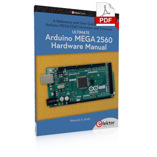
Elektor Digital Ultimate Arduino Mega 2560 Hardware Manual (E-book)
A Reference and User Guide for the Arduino Mega 2560 Hardware and Firmware A manual providing up-to-date hardware information for the Arduino Mega 2560. The Arduino Mega 2560 is an upgrade to the popular Arduino Uno board, providing more pins, serial ports and memory. Arduino is the easy to use open-source electronics platform used by hobbyists, makers, hackers, experimenters, educators and professionals. Get all the information that you need on the hardware and firmware found on Arduino Mega 2560 boards in this handy reference and user guide. Ideal for the workbench or desktop. This manual covers the Arduino Mega 2560 hardware and firmware, and is a companion volume to the Ultimate Arduino Uno Hardware Manual, which covers the Arduino Uno hardware and firmware. Contains all of the Arduino Mega 2560 hardware information in one place Covers Arduino / Genuino Mega 2560 revision 3 and earlier boards Easily find hardware technical specifications with explanations Pin reference chapter with interfacing examples Diagrams and illustrations for easy reference to pin functions and hardware connections Learn to back up and restore firmware on the board, or load new firmware Basic fault finding and repair procedures for Arduino Mega 2560 boards Power supply circuits simplified and explained Mechanical dimensions split into five easy to reference diagrams Contains circuit diagrams, parts list and board layout to easily locate components A chapter on shield compatibility explains how shields work across different Arduino boards
€ 32,95
Members: € 29,66
-

Elektor Digital Ultimate Arduino Uno Hardware Manual (E-book)
A Reference and User Guide for the Arduino Uno Hardware and Firmware A manual providing up-to-date hardware information for the popular Arduino Uno, the easy to use open-source electronics platform used by hobbyists, makers, hackers, experimenters, educators and professionals. Get all the information that you need on the hardware and firmware found on Arduino Uno boards in this handy reference and user guide. ldeal for the workbench or desktop Contains all of the Arduino Uno hardware information in one place Covers Arduino / Genuino Uno revision 3 and earlier boards Easily find hardware technical specifications with explanations Pin reference chapter with interfacing examples Diagrams and illustrations for easy reference to alternate pin functions and hardware connections Learn to back up and restore firmware on the board, or load new firmware Basic fault finding and repair procedures for Arduino Uno boards Power supply circuits simplified and explained Mechanical dimensions split into five easy to reference diagrams Contains circuit diagrams, parts list and board layout reference to easily locate components
€ 29,95
Members: € 26,96
-
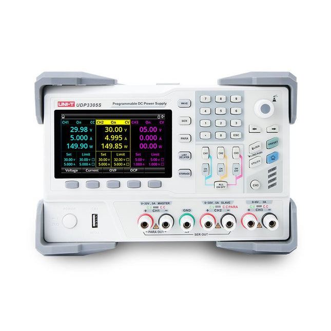
Uni-Trend UNI-T UDP3305S-E DC Power Supply (328 W)
The UDP3305S-E is a high-performance programmable linear DC power supply. It has a clear LCD user interface, excellent performance indicators, a variety of analysis functions and communication interfaces. It can meet the diversified test needs of users. It aims to provide cost-effective DC programmable power supply equipment for teaching, scientific research, industry and other fields. LCD interactive interface Using a 4.3-inch high-definition display screen, it provides users with a man-machine interface with rich functions and simple operation, which can display the current set output voltage/current, actual output voltage/current and protection output voltage/current value of the power supply in real time. The functional interface is simple and comprehensive, easy to operate. One-key setting for series and parallel The series-parallel connection between CH1 and CH2 of the main channel can be realized without external connection, which simplifies the connection and makes the test easier. List/Delayer function With list and delay setting functions, it can set up to 2048 sets of data according to test requirements, and the number of cycles can reach 99999. It is used with waveform templates, which is very convenient for cycle testing and aging testing. Rich remote control interface Standard RS232 communication interface, Ethernet interface, Digital I/O and master and slave USB interfaces, can be controlled by remote connection to Ethernet, or through RS232 and USB, with the host computer software to achieve software control. Specifications Type Linear DC power supply Channels 4 Total power 328 W Output voltage CH1/CH2: 0~30 VCH3: 0~6 VCH4: 5 V Output current CH1/CH2: 0~5 ACH3: 0~3 ACH4: 2 A Resolution 10 mV, 1 mA Setting accuracy 0.3% +20 mV<0.2% +5 mA Connectivity USB Device, RS-232, LAN, USB host, Digital I/O Included 1x UDP3305S-E DC Power Supply 1x Power cord 1x USB cable Downloads Datasheet User manual Programming manual Software V1.0 Firmware V1.10
€ 396,54
-

Uni-Trend UNI-T UPO1202CS 2-ch Oscilloscope (200 MHz)
UNI-T UPO1202CS is a multifunctional, low-cost 2-channel digital phosphor oscilloscope with 200 MHz bandwidth and 1 GSa/s sampling rate. It can be widely used in the fields of electronic and electrical design, debugging, education and industrial design. UPO1000CS series adopts parallel digital signal processing technology, which greatly improves the data processing speed and waveform capture rate. The original Ultra Phosphor technology can present the cumulative effect of the tested signal as a multi-layered afterglow. Compared with traditional digital storage oscilloscopes, the persistence of digital phosphor oscilloscopes can present three-dimensional waveform data of amplitude, time and signal intensity. Fast Acquire technology can accurately capture abnormal events such as video, jitter, noise and runt signals. Specifications UPO1102CS UPO1202CS Bandwidth 100 MHz 200 MHz Analog channels 2 2 Sampling rate 1 GSa/s 1 GSa/s Storage depth 56 Mpts per channel 56 Mpts per channel Rise time ≤3.5ns ≤1.8ns Capture rate 500,000 wfms/s 500,000 wfms/s Waveform record 100,000 frames 100,000 frames Features 7' WVGA (800 x 480) TFT LCD Ultra Phosphor super fluorescent display effect, up to 256 levels of gray display Support RS232, I²C, SPI, CAN and LIN trigger Innovative RS232, I²C, SPI, CAN and LIN hardware decoding Vertical scale: 1 mV/div-20 V/div Low background noise: <100 μVrms 1M points enhanced FFT function. Support frequency setting, waterfall diagram, detection setting and marker measurement etc 36 kinds of waveform parameters can be automatically measured Rich trigger functions (edge, pulse width, video, slope, runt, overshoot, delay, timeout, duration, setup and hold, Nth edge and pattern trigger) Multi-Scopes support dual-channel independent trigger fluorescence display Multi-channel independent 7-bit hardware frequency counter DVM supports dual-channel independent AC and DC true RMS measurement Waveform arithmetic functions (FFT, +, -, ×, ÷, digital filtering, logic operations, and advanced operations) Rich interfaces: USB Host, USB Device, LAN, EXT Trig, AUX Out (Trig Out, Pass/Fail) Support SCPI programmable instrument standard command Support WEB access and control Downloads Datasheet Programming Manual User's Manual Quick Start Guide Software
€ 369,00
-
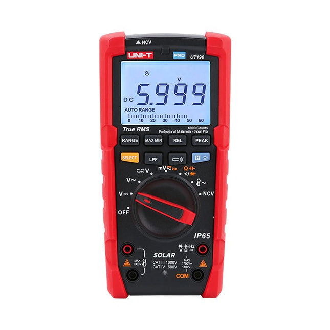
Uni-Trend UNI-T UT196 True RMS Solar Multimeter
The UT196 True RMS solar multimeter is an ideal tool for solar power system maintenance. This rugged meter is designed for technicians who work in rugged outdoor environments. UT196 can measure up to 1700 V DC and 1500 V AC voltages, and 3000 A AC current with an external current clamp sensor. This solar meter offers IP65 protection and able to withstand 2 m drop as well. The UT196 solar multimeter is designed with 1700 V DC, 1500 Vrms AC overload protection and tested for safe usage in CAT III 1000 V, CAT IV 600 V environments. Features True RMS Measure up to 1700 V DC and 1500 V AC for high voltage applications e.g. solar array, wind IP65 protection CAT III 1000V, CAT IV 600 V Analog bar Frequency response: 45 Hz~1 kHz Low-pass filter function Low impedance mode Built-in flashlight, bright backlight and visual alarm Applications High DC voltage measurement Output voltage and frequency measurement Voltage and frequency measurement Current and frequency measurement Specifications Range UT196 DC voltage (V) 1700 V ±0.2% +5 AC voltage (V) 1500 V ±0.8% +3 Frequency (Hz) 1 MHz ±0.08% +4 Resistance (Ω) 60 MΩ ±0.8% +2 Capacitance (F) 60 mF ±1.9% +5 Power 9 V battery Dimensions 195 x 95 x 58 mm Included UT196 Solar Multimeter Battery Test leads Downloads Datasheet Manual
€ 129,63
-
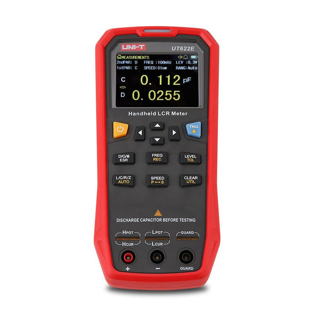
Uni-Trend UNI-T UT622E LCR Meter
The UT622E handheld LCR meter features powerful functions, high accuracy, fast speed, and long standby time. With a clear and intuitive 2.8-inch TFT LCD display, large-capacity rechargeable battery, and 100 kHz test frequency, the meter can be used for longstanding accurate and convenient measurement in any occasion. It is suitable for the measurement and screening of inductance, capacitance, and resistance in laboratories, production lines, maintenance points, etc. Features Max. test frequency: 100 kHz Accuracy: 0.1% Display count: 99999 Max. test rate: 20 times/s DCR: Yes Connectivity: Mini-USB Display: 2.8" TFT LCD Specifications Testfrequency 100 Hz, 120 Hz, 1 kHz, 10 kHz, 100 kHz Test level 0.1 Vmrs, 0.3 Vrms, 1 Vrms Output impedance 100 Ω Measurement parameters Primary: L/C/R/Z/DCRSecondary: D/Q/Θ/ESR DSR speed test Fast (20 times/s), medium (5 times/s), or slow (2 times/s) Range Auto/Hold Tolerance range 1%~20% Equivalent mode Series/Parallel Clearing connection Open/Short circuit Fuse of test ports 0.1 A/250 V Communication interface Mini-USB MAX reading of primary parameters 99999 MIN resolution 0.0001 Maximum accuracy 0.10% L 0.00 µH~99.999 H C 0.00 pF~99.999 mF Z/R 0.0000 Ω~9.9999 MΩ ESR 0.0000 Ω~999.99 Ω D 0.0000~9.9999 Q 0.0000~99999 Θ -179.9°~179.9° DCR 0.01 mΩ~20.000 MΩ Power supply 3.7 V/1800 mAh lithium polymer battery Display 2.8" TFT LCD (320x240) Dimensions 93 x 192 x 44 mm Weight 420 g Included UT622E LCR meter Short circuit board Four-terminal kelvin test leads USB cable Manual Downloads Datasheet Manual Software
€ 325,49


