Products
-

Speciale Elektor / E&M: 33 Progetti Top di Elettronica
Una ricca selezione di articoli dal Mondo Elektor! Gli articoli di questo libro sono una selezione accurata, il "meglio del meglio" di circuiti e progetti recenti, realizzati da tecnici di grande talento provenienti da tutto il mondo. Nel tipico stile di Elektor, questa raccolta offre qualcosa di interessante per tutti, dai progettisti esperti a coloro che praticano l'elettronica nel tempo libero. Sommario Super Servo TesterProva Fino a Quattro Servocomandi, Stand-Alone o in Sistema The TubeUn Insolito Amplificatore a Valvole Cloc 2.0La Sveglia che Avete Sempre Desiderato Stazione Meteo LoRa Low-PowerCostruitevi una Stazione Meteorologica “Long Range” Uscita Video con Microcontrollori (Parte 1)Video Composito Uscita Video con Microcontrollori (Parte 2)Uscita VGA e DVI Un Raspberry Pi Pico come Analizzatore di SpettroFFT su Base Hardware a Basso Costo PIC O’Clock – In Contatto col TempoProgettare un Ricevitore di Segnali Orari SDR Frequenzimetro di Rete ACMisura Frequenza e Tensione della Rete Elettrica Generatore di Funzioni con Arduino NanoNano + Codice = Generatore di Funzioni Monitor CO2Un Approccio Fai-Da-Te per Il Controllo della Qualità dell‘Aria ChatMagLevLa Levitazione Magnetica con AI Alimentatore Lineare Variabile Combinato0…50 V / 0…2 A con Struttura Simmetrica Duale Ricevitore Digitale FM con Arduino e TEA5767Restate in Ascolto con un Arduino Nano Protezione Antigelo per Piante da FruttoCon Registrazione della Temperatura Carico Elettronico con Generatore di clock IntegratoPer Collaudare Alimentatori, Convertitori di Tensione e Batterie 128 Termostato Web con ESP32Mantieni il Vino alla Giusta Temperatura Iniezione di Segnali e di Potenza......per Rilevare le Interruzioni nei Cavi DIY LiPo Supercharger KitDal Prototipo al Mercato di Massa Livella Digitale con Stroboscopio AttivoCalibra il Tuo giradischi con Questo Strumento "Tutto-in-Uno" The Game of Life – 262.144 Modi di GiocareDal Progetto di un Lettore Rilevatore di PerditeCollegato ad Arduino Cloud Orologio di LissajousL’Incedere del Tempo con le Figure di Lissajous Mastermind – Controllato da ArduinoUna Versione Moderna del Classico Gioco di Decifrazione Generatore Audio Analogico 1 kHzOnda Sinusoidale a Bassa Distorsione Aggiorna il tuo Caricabatteria (Parte 1)Non Buttarlo, Modificalo! Aggiorna il tuo Caricabatteria (Parte 2)Non Buttarlo, Modificalo! Sistemi GNSS RTK a Basso CostoCon Accuratezza a Livello Centimetrico Esperimenti a 10 GHz con LNB Satellitari ModificatiSbloccare la Banda X a Basso Costo Telecamera per FerromodellismoInstalla un Modulo ESP32 CAM a Bordo! Monitor di Tensione con MicrocontrolloreProtezione dalla Scarica Profonda per Batterie e Altro Nodo Sensore AutonomoTrasmissione Dati LoRa con Alimentazione a Batterie Solari Layout e Sicurezza sul PCBConsigli per un Progetto Sicuro e Durevole
€ 29,95
Members: € 26,96
-

Elektor Digital Speciale Elektor / E&M: 33 Progetti Top di Elettronica (PDF)
Una ricca selezione di articoli dal Mondo Elektor! Gli articoli di questo libro sono una selezione accurata, il "meglio del meglio" di circuiti e progetti recenti, realizzati da tecnici di grande talento provenienti da tutto il mondo. Nel tipico stile di Elektor, questa raccolta offre qualcosa di interessante per tutti, dai progettisti esperti a coloro che praticano l'elettronica nel tempo libero. Sommario Super Servo TesterProva Fino a Quattro Servocomandi, Stand-Alone o in Sistema The TubeUn Insolito Amplificatore a Valvole Cloc 2.0La Sveglia che Avete Sempre Desiderato Stazione Meteo LoRa Low-PowerCostruitevi una Stazione Meteorologica “Long Range” Uscita Video con Microcontrollori (Parte 1)Video Composito Uscita Video con Microcontrollori (Parte 2)Uscita VGA e DVI Un Raspberry Pi Pico come Analizzatore di SpettroFFT su Base Hardware a Basso Costo PIC O’Clock – In Contatto col TempoProgettare un Ricevitore di Segnali Orari SDR Frequenzimetro di Rete ACMisura Frequenza e Tensione della Rete Elettrica Generatore di Funzioni con Arduino NanoNano + Codice = Generatore di Funzioni Monitor CO2Un Approccio Fai-Da-Te per Il Controllo della Qualità dell‘Aria ChatMagLevLa Levitazione Magnetica con AI Alimentatore Lineare Variabile Combinato0…50 V / 0…2 A con Struttura Simmetrica Duale Ricevitore Digitale FM con Arduino e TEA5767Restate in Ascolto con un Arduino Nano Protezione Antigelo per Piante da FruttoCon Registrazione della Temperatura Carico Elettronico con Generatore di clock IntegratoPer Collaudare Alimentatori, Convertitori di Tensione e Batterie 128 Termostato Web con ESP32Mantieni il Vino alla Giusta Temperatura Iniezione di Segnali e di Potenza......per Rilevare le Interruzioni nei Cavi DIY LiPo Supercharger KitDal Prototipo al Mercato di Massa Livella Digitale con Stroboscopio AttivoCalibra il Tuo giradischi con Questo Strumento "Tutto-in-Uno" The Game of Life – 262.144 Modi di GiocareDal Progetto di un Lettore Rilevatore di PerditeCollegato ad Arduino Cloud Orologio di LissajousL’Incedere del Tempo con le Figure di Lissajous Mastermind – Controllato da ArduinoUna Versione Moderna del Classico Gioco di Decifrazione Generatore Audio Analogico 1 kHzOnda Sinusoidale a Bassa Distorsione Aggiorna il tuo Caricabatteria (Parte 1)Non Buttarlo, Modificalo! Aggiorna il tuo Caricabatteria (Parte 2)Non Buttarlo, Modificalo! Sistemi GNSS RTK a Basso CostoCon Accuratezza a Livello Centimetrico Esperimenti a 10 GHz con LNB Satellitari ModificatiSbloccare la Banda X a Basso Costo Telecamera per FerromodellismoInstalla un Modulo ESP32 CAM a Bordo! Monitor di Tensione con MicrocontrolloreProtezione dalla Scarica Profonda per Batterie e Altro Nodo Sensore AutonomoTrasmissione Dati LoRa con Alimentazione a Batterie Solari Layout e Sicurezza sul PCBConsigli per un Progetto Sicuro e Durevole
€ 24,95
Members: € 22,46
-

SunFounder SunFounder Kepler Kit (Ultimate Starter Kit for Raspberry Pi Pico W)
Your gateway to IoT and microcontroller programming With 450+ components and 117 online projects, this comprehensive kit ignites your creativity. The tutorials by Paul McWhorter make learning enjoyable for beginners and advanced users. This kit supports MicroPython, C/C++, and Piper Make, offering diverse programming options. Explore sensors, actuators, LEDs, and LCDs for endless project possibilities. From home automation to robotics, this kit empowers your tech journey. Features IoT Starter Kit for Beginners: This kit offers a rich IoT learning experience for beginners. With 450+ components, 117 projects, and expert-led video lessons, this kit makes learning microcontroller programming and IoT engaging and accessible. Expert-Guided Video Lessons: The kit includes 27 video tutorials by the renowned educator, Paul McWhorter. His engaging style simplifies complex concepts, ensuring an effective learning experience in microcontroller programming. Wide Range of Hardware: The kit includes a diverse array of components like sensors, actuators, LEDs, LCDs, and more, enabling you to experiment and create a variety of projects with the Raspberry Pi Pico W. Supports Multiple Languages: The kit offers versatility with support for three programming languages - MicroPython, C/C++, and Piper Make, providing a diverse programming learning experience. Dedicated Support: Benefit from our ongoing assistance, including a community forum and timely technical help for a seamless learning experience. Included Raspberry Pi Pico W Breadboard Jumper Wires Resistor Transistor Capacitor Diode Li-po Charger Module 74HC595 TA6586 – Motor Driver Chip LED RGB LED LED Bar Graph 7-segment Display 4-Digit 7-Segment Display LED Dot Matrix I²C LCD1602 WS2812 RGB 8 LEDs Strip Buzzer DC Motor Servo DC Water Pump Relay Button Micro Switch Slide Switch Potentiometer Infrared Receiver Joystick Module 4x4 Keypad MPR121 Module MFRC522 Module Photoresistor Thermistor Tilt Switch Reed Switch PIR Motion Sensor Module Water Level Sensor Module Ultrasonic Module DHT11 Humiture Sensor MPU6050 Module Documentation Online Tutorials in 3 languages (EN, DE and JP)
-

Elektor Digital Technical Modeling with OpenSCAD (E-book)
Create Models for 3D Printing, CNC Milling, Process Communication and Documentation Engineers dread designing 3D models using traditional modeling software. OpenSCAD takes a refreshing and completely different approach. Create your models by arranging geometric solids in a JavaScript-like language, and use them with your 3D printer, CNC mill, or process communication. OpenSCAD differs from other design systems in that it uses programmatical modeling. Your model is made up of primitives that are invoked using a C-, Java- or Python-like language. This approach to model design is close to the “mechanical work” done in the real world and appeals to engineers and others who are not a member of the traditional creative class. OpenSCAD also provides a wide variety of comfort functions that break the 1:1 relationship between code and geometry. This book demonstrates the various features of the programming language using practical examples such as a replacement knob for a LeCroy oscilloscope, a wardrobe hanger, a container for soap dispensers, and various other real-life examples. Written by an engineer with over 15 years of experience, this book is intended for Linux and Windows users alike. If you have programming experience in any language, this book will have you producing practical three-dimensional objects in short order!
€ 29,95
Members: € 26,96
-

Elektor Publishing Tektronix 7000 Series Mainframes
The Most Iconic Oscilloscopes in Electronics History The 7000 Series was the most iconic family of oscilloscopes in the history of technology. Introduced in 1969 by Tektronix, the sector’s leader at the time, this remarkable line of instruments defined an era and became a benchmark for generations of engineers, researchers, and technicians. Throughout the 1970s and well beyond, 7000-Series oscilloscopes were a constant presence in laboratories, universities, and industrial facilities around the world. Their modular plug-in architecture, exceptional flexibility, and outstanding performance embodied the engineering philosophy that made Tektronix synonymous with accuracy, innovation, and reliability. This book offers an in-depth exploration of the 7000-Series oscilloscopes, combining historical context, technical analysis, and practical insight into their design and restoration. Conceived as a continuation of Tektronix Epic Oscilloscopes, this work expands the subject into two volumes: the first devoted to mainframes and core technologies, the second focused entirely on plug-ins.
€ 69,95
Members: € 62,96
-
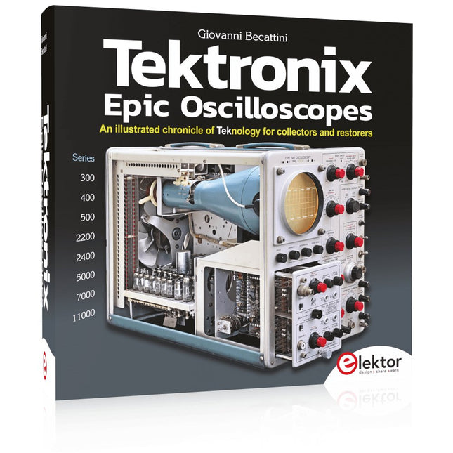
Elektor Publishing Tektronix Epic Oscilloscopes
An illustrated chronicle of Teknology for collectors and restorers Oscilloscopes have made a major contribution to the advancement of human knowledge, not only in electronics, but in all sciences, whenever a physical quantity can be converted into a timerelated electrical signal. This book traces the history of a crucial instrument through many Tektronix products. This is the company that invented and patented most of the functions found in all oscilloscopes today. Tek is and will always be synonymous with the oscilloscope. In nearly 600 pages, with hundreds of gorgeous photos, diagrams, anecdotes, and technical data, you'll travel through the history of Tektronix in a superb collector's edition with a technical point of view. The author is not afraid to get his hands dirty restoring his own Tek equipment. The journey starts in the early 1950s. It ends in the '90s, after exploring the ins and outs of the most interesting models in the 300, 400, 500, 5000, 7000, and 11000 series, from tubes to advanced hybrid technologies. Downloads NEW: Free Supplement (136 pages, 401 MB)
€ 79,95
Members: € 71,96
-
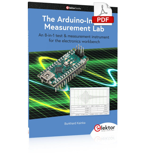
Elektor Digital The Arduino-Inside Measurement Lab (E-book)
An 8-in-1 test & measurement instrument for the electronics workbench A well-equipped electronics lab is crammed with power supplies, measuring devices, test equipment and signal generators. Wouldn‘t it be better to have one compact device for almost all tasks? Based on the Arduino, a PC interface is to be developed that’s as versatile as possible for measurement and control. It simply hangs on a USB cable and – depending on the software – forms the measuring head of a digital voltmeter or PC oscilloscope, a signal generator, an adjustable voltage source, a frequency counter, an ohmmeter, a capacitance meter, a characteristic curve recorder, and much more. The circuits and methods collected here are not only relevant for exactly these tasks in the "MSR" electronics lab, but many details can also be used within completely different contexts.
€ 29,95
Members: € 26,96
-

Elektor Publishing The BeagleY-AI Handbook
A Practical Guide to AI, Python, and Hardware Projects Welcome to your BeagleY-AI journey! This compact, powerful, and affordable single-board computer is perfect for developers and hobbyists. With its dedicated 4 TOPS AI co-processor and a 1.4 GHz Quad-core Cortex-A53 CPU, the BeagleY-AI is equipped to handle both AI applications and real-time I/O tasks. Powered by the Texas Instruments AM67A processor, it offers DSPs, a 3D graphics unit, and video accelerators. Inside this handbook, you‘ll find over 50 hands-on projects that cover a wide range of topics—from basic circuits with LEDs and sensors to an AI-driven project. Each project is written in Python 3 and includes detailed explanations and full program listings to guide you. Whether you‘re a beginner or more advanced, you can follow these projects as they are or modify them to fit your own creative ideas. Here’s a glimpse of some exciting projects included in this handbook: Morse Code Exerciser with LED or BuzzerType a message and watch it come to life as an LED or buzzer translates your text into Morse code. Ultrasonic Distance MeasurementUse an ultrasonic sensor to measure distances and display the result in real time. Environmental Data Display & VisualizationCollect temperature, pressure, and humidity readings from the BME280 sensor, and display or plot them on a graphical interface. SPI – Voltmeter with ADCLearn how to measure voltage using an external ADC and display the results on your BeagleY-AI. GPS Coordinates DisplayTrack your location with a GPS module and view geographic coordinates on your screen. BeagleY-AI and Raspberry Pi 4 CommunicationDiscover how to make your BeagleY-AI and Raspberry Pi communicate over a serial link and exchange data. AI-Driven Object Detection with TensorFlow LiteSet up and run an object detection model using TensorFlow Lite on the BeagleY-AI platform, with complete hardware and software details provided.
€ 44,95
Members: € 40,46
-

Elektor Digital The BeagleY-AI Handbook (E-book)
A Practical Guide to AI, Python, and Hardware Projects Welcome to your BeagleY-AI journey! This compact, powerful, and affordable single-board computer is perfect for developers and hobbyists. With its dedicated 4 TOPS AI co-processor and a 1.4 GHz Quad-core Cortex-A53 CPU, the BeagleY-AI is equipped to handle both AI applications and real-time I/O tasks. Powered by the Texas Instruments AM67A processor, it offers DSPs, a 3D graphics unit, and video accelerators. Inside this handbook, you‘ll find over 50 hands-on projects that cover a wide range of topics—from basic circuits with LEDs and sensors to an AI-driven project. Each project is written in Python 3 and includes detailed explanations and full program listings to guide you. Whether you‘re a beginner or more advanced, you can follow these projects as they are or modify them to fit your own creative ideas. Here’s a glimpse of some exciting projects included in this handbook: Morse Code Exerciser with LED or BuzzerType a message and watch it come to life as an LED or buzzer translates your text into Morse code. Ultrasonic Distance MeasurementUse an ultrasonic sensor to measure distances and display the result in real time. Environmental Data Display & VisualizationCollect temperature, pressure, and humidity readings from the BME280 sensor, and display or plot them on a graphical interface. SPI – Voltmeter with ADCLearn how to measure voltage using an external ADC and display the results on your BeagleY-AI. GPS Coordinates DisplayTrack your location with a GPS module and view geographic coordinates on your screen. BeagleY-AI and Raspberry Pi 4 CommunicationDiscover how to make your BeagleY-AI and Raspberry Pi communicate over a serial link and exchange data. AI-Driven Object Detection with TensorFlow LiteSet up and run an object detection model using TensorFlow Lite on the BeagleY-AI platform, with complete hardware and software details provided.
€ 34,95
Members: € 31,46
-

Elektor Publishing The Book of 555 Timer Projects
Over 45 Builds for the Legendary 555 Chip (and the 556, 558) The 555 timer IC, originally introduced by the Signetics Corporation around 1971, is sure to rank high among the most popular analog integrated circuits ever produced. Originally called the IC Time Machine, this chip has been used in many timer-related projects by countless people over decades. This book is all about designing projects based on the 555 timer IC. Over 45 fully tested and documented projects are presented. All projects have been fully tested by the author by constructing them individually on a breadboard. You are not expected to have any programming experiences for constructing or using the projects given in the book. However, it’s definitely useful to have some knowledge of basic electronics and the use of a breadboard for constructing and testing electronic circuits. Some of the projects in the book are: Alternately Flashing Two LEDs Changing LED Flashing Rate Touch Sensor On/Off Switch Switch On/Off Delay Light-Dependent Sound Dark/Light Switch Tone Burst Generator Long Duration Timer Chasing LEDs LED Roulette Game Traffic Lights Continuity Tester Electronic Lock Switch Contact Debouncing Toy Electronic Organ Multiple Sensor Alarm System Metronome Voltage Multipliers Electronic Dice 7-Segment Display Counter Motor Control 7-Segment Display Dice Electronic Siren Various Other Projects The projects given in the book can be modified or expanded by you for your very own applications. Electronic engineering students, people engaged in designing small electronic circuits, and electronic hobbyists should find the projects in the book instructive, fun, interesting, and useful.
€ 34,95
Members: € 31,46
-

Elektor Digital The Book of 555 Timer Projects (E-book)
Over 45 Builds for the Legendary 555 Chip (and the 556, 558) The 555 timer IC, originally introduced by the Signetics Corporation around 1971, is sure to rank high among the most popular analog integrated circuits ever produced. Originally called the IC Time Machine, this chip has been used in many timer-related projects by countless people over decades. This book is all about designing projects based on the 555 timer IC. Over 45 fully tested and documented projects are presented. All projects have been fully tested by the author by constructing them individually on a breadboard. You are not expected to have any programming experiences for constructing or using the projects given in the book. However, it’s definitely useful to have some knowledge of basic electronics and the use of a breadboard for constructing and testing electronic circuits. Some of the projects in the book are: Alternately Flashing Two LEDs Changing LED Flashing Rate Touch Sensor On/Off Switch Switch On/Off Delay Light-Dependent Sound Dark/Light Switch Tone Burst Generator Long Duration Timer Chasing LEDs LED Roulette Game Traffic Lights Continuity Tester Electronic Lock Switch Contact Debouncing Toy Electronic Organ Multiple Sensor Alarm System Metronome Voltage Multipliers Electronic Dice 7-Segment Display Counter Motor Control 7-Segment Display Dice Electronic Siren Various Other Projects The projects given in the book can be modified or expanded by you for your very own applications. Electronic engineering students, people engaged in designing small electronic circuits, and electronic hobbyists should find the projects in the book instructive, fun, interesting, and useful.
€ 29,95
Members: € 26,96
-

Elektor Digital The Bottle Builder (E-book)
The author, Johan Basse Bergqvist, is an engineer, a musician, and an audiophile with a knack for building projects that produce the desired results. The combination of these skills leads to a uniquely valuable perspective on audio design that is routinely reflected in the book and passed on to the readers. Several design projects are provided, 40 in total. The designs are explained, and the unique features or methods he uses are described in further detail. Each design includes detailed schematics and a complete parts list. Many of the projects also include layout documentation in the form of CAD photos of the PCB layouts. The range of projects is very diverse and includes something that will appeal to everyone. Stereo amplifiers, guitar and bass amplifiers, preamplifiers for phono, and microphones are all covered. Several variants for each type are included, and the power amplifier designs range from a few watts to several hundred watts, which meet almost any power level you might tackle.
€ 64,95
Members: € 58,46
-
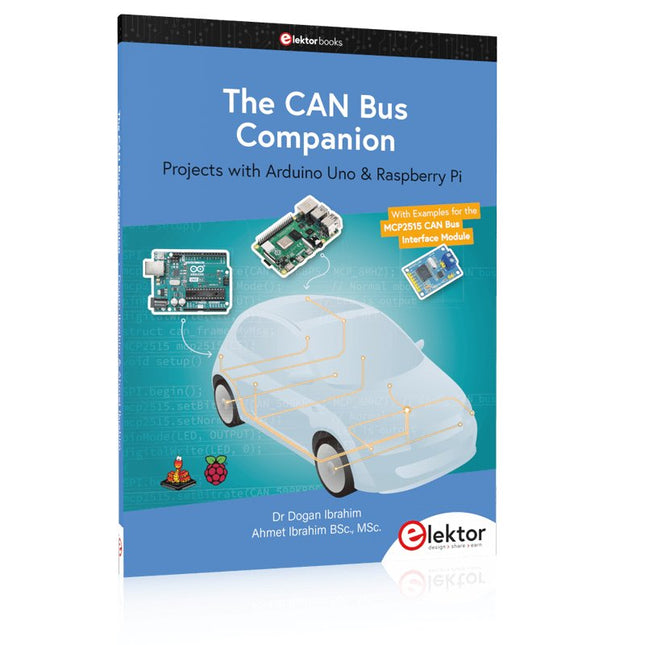
Elektor Publishing The CAN Bus Companion
This book details the use of the Arduino Uno and the Raspberry Pi 4 in practical CAN bus based projects. Using either the Arduino Uno or the Raspberry Pi with off-the-shelf CAN bus interface modules considerably ease developing, debugging, and testing CAN bus based projects. This book is written for students, practicing engineers, enthusiasts, and for everyone else wanting to learn more about the CAN bus and its applications. The book assumes that the reader has some knowledge of basic electronics. Knowledge of the C and Python programming languages and programming the Arduino Uno using its IDE and Raspberry Pi will be useful, especially if the reader intends to develop microcontroller-based projects using the CAN bus. The book should be a useful source of reference material for anyone interested in finding answers to questions such as: What bus systems are available for the automotive industry? What are the principles of the CAN bus? How can I create a physical CAN bus? What types of frames (or data packets) are available in a CAN bus system? How can errors be detected in a CAN bus system and how dependable is a CAN bus system? What types of CAN bus controllers exist? How do I use the MCP2515 CAN bus controller? How do I create 2-node Arduino Uno-based CAN bus projects? How do I create 3-node Arduino Uno-based CAN bus projects? How do I set the acceptance masks and acceptance filters? How do I analyze data on the CAN bus? How do I create 2-node Raspberry Pi-based CAN bus projects? How do I create 3-node Raspberry Pi-based CAN bus projects?
€ 34,95
Members: € 31,46
-
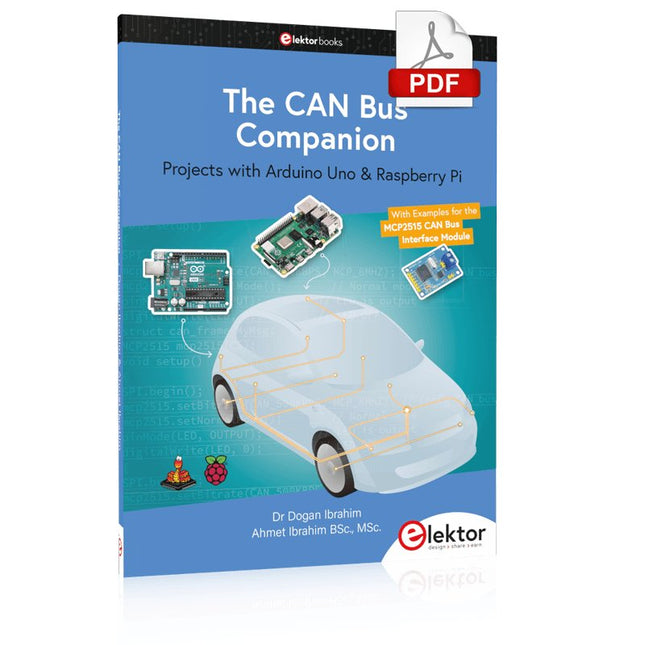
Elektor Digital The CAN Bus Companion (E-book)
Projects with Arduino Uno & Raspberry Pi with Examples for the MCP2515 CAN Bus Interface Module This book details the use of the Arduino Uno and the Raspberry Pi 4 in practical CAN bus based projects. Using either the Arduino Uno or the Raspberry Pi with off-the-shelf CAN bus interface modules considerably ease developing, debugging, and testing CAN bus based projects. This book is written for students, practicing engineers, enthusiasts, and for everyone else wanting to learn more about the CAN bus and its applications. The book assumes that the reader has some knowledge of basic electronics. Knowledge of the C and Python programming languages and programming the Arduino Uno using its IDE and Raspberry Pi will be useful, especially if the reader intends to develop microcontroller-based projects using the CAN bus. The book should be a useful source of reference material for anyone interested in finding answers to questions such as: What bus systems are available for the automotive industry? What are the principles of the CAN bus? How can I create a physical CAN bus? What types of frames (or data packets) are available in a CAN bus system? How can errors be detected in a CAN bus system and how dependable is a CAN bus system? What types of CAN bus controllers exist? How do I use the MCP2515 CAN bus controller? How do I create 2-node Arduino Uno-based CAN bus projects? How do I create 3-node Arduino Uno-based CAN bus projects? How do I set the acceptance masks and acceptance filters? How do I analyze data on the CAN bus? How do I create 2-node Raspberry Pi-based CAN bus projects? How do I create 3-node Raspberry Pi-based CAN bus projects?
€ 29,95
Members: € 26,96
-
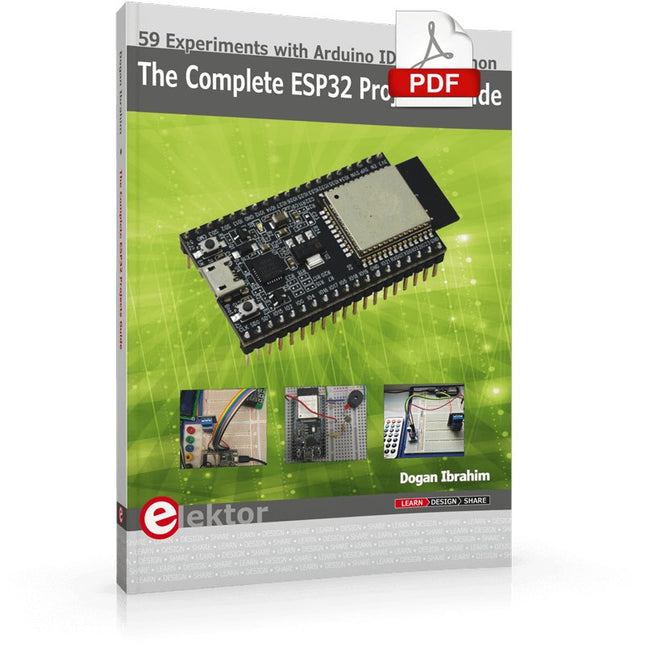
Elektor Digital The Complete ESP32 Projects Guide (E-book)
59 Experiments with Arduino IDE and Python The main aim of this book is to teach the Arduino IDE and MicroPython programming languages in ESP32 based projects, using the highly popular ESP32 DevKitC development board. Many simple, basic, and intermediate level projects are provided in the book using the Arduino IDE with ESP32 DevKitC. All projects have been tested and work. Block diagrams, circuit diagrams, and complete program listings of all projects are given with explanations. In addition, several projects are provided for programming the ESP32 DevKitC using MicroPython. The projects provided in this book are designed to teach the following features of the ESP32 processor: GPIOs Touch sensors External interrupts Timer interrupts I²C and I²S SPI PWM ADC DAC UART Hall sensor Temperature sensor Infrared controller Reading and writing to SD card Reading and writing to flash memory RTC timer Chip ID Security and encryption Wi-Fi and network programming Bluetooth BLE programming Communication mobile devices Low power design ESP-IDF programming The projects have been organized with increasing levels of difficulty. Readers are encouraged to tackle the projects in the order given. A specially prepared hardware kit (SKU 18305) is available from Elektor. With the help of this hardware, it should be easy and fun to build the projects in this book.
€ 34,95
Members: € 31,46
-

Elektor Classics The Complete Linear Audio Library (USB Stick)
Jan Didden created Linear Audio in 2010 and published 14 Volumes between 2010 and 2017. Each 200-page Volume contains on average 10 articles by expert authors in the field of audio, acoustics, and instrumentation. Whether you are interested in tube amplifiers, solid-state equipment, loudspeaker design, capacitor and resistor distortion or distortion measurement, you are certain to find helpful advice and interesting discussions. From beginner to advanced level, for the audio professional or the serious hobbyist, this ExpertCollection will advance your understanding and offer new perspectives on common issues. Bonus material included with this collection is a 5-part YouTube series on negative feedback as applied to audio by renowned author Jan Didden, and nine additional landmark audio articles and presentations. If you are seriously interested in audio, acoustics, and instrumentation, you can’t afford to miss this! The published material is indexed and fully searchable and will provide an almost limitless resource for many years to come. You can read about Linear Audio’s authors, and the Table of Contents of each Volume, at linearaudio.net.
€ 149,95€ 74,95
Best Price
-

Elektor Publishing The Connected Autonomous Vehicle and its Environment
An Introduction to Real and Reduced-Scale Autonomous Vehicles Want to cut through the hype and get to the core of autonomous and connected vehicles? Then this book is your clear, accessible guide to a complex and fast-moving field. Starting with Intelligent Transport Systems (ITS), it walks you through the essential foundations, including Advanced Driver Assistance Systems (ADAS) – the stepping stones to full autonomy. Explore how self-driving cars mimic human behavior through a loop of perception, analysis, decision, and action. Discover the key functions that make it possible: localization, obstacle detection, driver monitoring, cooperative awareness – and the most challenging of all, trajectory planning, across strategic, tactical, and operational levels. Will vehicles be connected? The debate is on – but the standards are already here. Learn how connectivity, infrastructure, and vehicles can work in synergy through the innovative concept of floating car data (FCD). Dive into real-world implementation: with embedded electronics account-ing for over 30% of a modern vehicle‘s cost, we unpack the architecture, coordination, and tools required to manage the complexity – brought to life with a hands-on case study. To finish, we open the door to the future: building your own 1:10 scale autonomous vehicle. No plug-and-play solutions – just the foundations for a collaborative, creative, and geek-friendly challenge. Let’s drive the future together.
€ 34,95
Members: € 31,46
-

Elektor Digital The Connected Autonomous Vehicle and its Environment (E-book)
An Introduction to Real and Reduced-Scale Autonomous Vehicles Want to cut through the hype and get to the core of autonomous and connected vehicles? Then this book is your clear, accessible guide to a complex and fast-moving field. Starting with Intelligent Transport Systems (ITS), it walks you through the essential foundations, including Advanced Driver Assistance Systems (ADAS) – the stepping stones to full autonomy. Explore how self-driving cars mimic human behavior through a loop of perception, analysis, decision, and action. Discover the key functions that make it possible: localization, obstacle detection, driver monitoring, cooperative awareness – and the most challenging of all, trajectory planning, across strategic, tactical, and operational levels. Will vehicles be connected? The debate is on – but the standards are already here. Learn how connectivity, infrastructure, and vehicles can work in synergy through the innovative concept of floating car data (FCD). Dive into real-world implementation: with embedded electronics account-ing for over 30% of a modern vehicle‘s cost, we unpack the architecture, coordination, and tools required to manage the complexity – brought to life with a hands-on case study. To finish, we open the door to the future: building your own 1:10 scale autonomous vehicle. No plug-and-play solutions – just the foundations for a collaborative, creative, and geek-friendly challenge. Let’s drive the future together.
€ 29,95
Members: € 26,96
-

Elektor Digital The EAGLE Companion (E-book)
EAGLE – the “Easily Applicable Graphical Layout Editor“ is a professional-grade CAD (computer aided design) software package for the design and drafting of electronic schematics as well as the design and fabrication of printed circuit boards (PCBs). This Advanced User Guide provides the experienced EAGLE user with insight into using some of the more advanced features of EAGLE software. It is not a guide to teach the reader the basic concepts of EAGLE, nor does it discuss the ‘how to’ of the EAGLE interface and the simpler operations and commands of the software. That is the purpose of the author’s previous title EAGLE V6 Getting Started Guide also published by Elektor. This eBook is intended as an enduring document covering the more advanced modules, commands, and functions which make up EAGLE. It is hoped that this eBook will provide a quick, succinct reference to assist with more complex applications and uses of EAGLE – an ‘EAGLE User’s Companion’, if you like. Complementing the EAGLE Advanced User Guide, the EAGLE User Language manual is included in this eBook in unabridged form, reproduced with permission of CadSoft GmbH. At the time of writing, the material in this eBook covers version 7 of the EAGLE software suite.
€ 39,95
Members: € 35,96
-

Elektor Classics The Elektor Arduino Collection (USB Stick)
This USB Stick contains more than 300 Arduino-related articles published in Elektor Magazine. The content includes both background articles and projects on the following topics: Software & hardware development: Tutorials on Arduino software development using Arduino IDE, Atmel Studio, Shields, and essential programming concepts. Learning: The Microcontroller Bootcamp offers a structured approach to programming embedded systems. Data acquisition & measurement: Projects such as a 16-bit data logger, lathe tachometer, and an AC grid analyzer for capturing and analyzing real-time signals. Wireless communication: Learn how to implement wireless networks, create an Android interface, and communicate effectively with microcontrollers. Robotics and automation: This covers the Arduino Nano Robot Controller, supporting boards for automation, and explores various Arduino shields to enhance functionality. Self-build projects: Unique projects such as laser projection, Numitron clock and thermometer, ELF receiver, Theremino, and touch LED interfaces highlight creative applications. Whether you're a beginner or an experienced maker, this collection is a valuable resource for learning, experimenting, and pushing the boundaries of Arduino technology.
€ 49,95€ 34,95
Best Price
-

Elektor Classics The Elektor Audio Collection 2026 (USB Stick)
More than 475 Audio Circuits from 30 Years of Elektor This USB Stick contains over 475 different audio circuits from the volumes 1995-2025 of Elektor. The article search feature allows you to search full-text content. The results are always displayed as pre-formatted PDF documents. Highlights Surround-sound decoder Compact amp Sampling rate converter Battery powered preamplifier Titan 2000 amplifier Crescendo Millennium amplifier Audio-DAC/ADC IR-S/PDFI receiver and transmitter High-End Power Amp Hi-fi Wireless Headset Paraphase Tone Control and more… On the Stick you will also find a folder with additional material such as PCB layouts, Gerber files and software. Specifications Storage 16 GB Interfaces 1x USB-A1x USB-C System requirements PC with Adobe Reader 7.0 or higher Web browser
€ 49,95€ 39,95
Best Price
-
Elektor Classics The Elektor Circuit Collection 2025 (USB Stick)
3K5 Noteworthy Designs (1975-2025) This USB archive stick contains over 3,500 noteworthy circuits from all areas of electronics (audio & video, hobby & modelling, home & garden, test & measurement, computers & microcontrollers, radio, power supplies & batteries) published in Elektor Magazine since 1975. Most circuits are sourced from the Elektor Summer Circuits editions. You can use the article search function to find specific content in the full text. The results are always shown as preformatted PDF documents. Adobe Reader may be used to browse articles as well as find individual words and expressions using the program’s integrated Search functions. Please note that no Summer Circuits editions were published between 2014 and 2022, so these years are not included in the directory. Specifications Storage 32 GB Connectors 1x USB-A1x USB-C
-

Elektor Classics The Elektor Power Supply Collection 2026 (USB Stick)
More than 275 Power Supply Designs for Home Construction This USB Stick contains over 275 different power supply circuits from the volumes 2001-2025 of Elektor. The article search feature allows you to search full-text content. The results are always displayed as pre-formatted PDF documents. Highlights Cuk Converter Automatic Battery Switchover Battery Voltage LED Digital Benchtop Power Supply Lithium-Ion Charger Solar Cell Charger Electronic Fuse High Voltage Regulator Power Supply for USB Devices Step-up Converter for LEDs Battery Management and much more... On the Stick you will also find a folder with additional material such as PCB layouts, Gerber files and software. Specifications Storage 16 GB Interfaces 1x USB-A1x USB-C System requirements PC with Adobe Reader 7.0 or higher Web browser
€ 49,95€ 39,95
Best Price
-

The Elektor RF & Communications Collection (USB Stick)
This USB stick holds a selection of more than 350 articles on RF, Radio and Communication published in Elektor Magazine. The content consists of both background articles and projects with the following topics: Basic radio-related circuits as well as more complex circuits like filters, oscillators, and amplifiers. Design, construction, and theory of antennas for transmitting and receiving radio signals efficiently. Design and analysis of RF circuits including filters, mixers, PLLs, and frequency synthesizers. Tools and techniques for predicting radio wave propagation paths and measuring RF signal strength. Techniques for processing digital signals in RF systems, including modulation and demodulation methods. Projects on radio receivers, AM, FM, SSB, CW, DRM, DAB, DAB+, Software Defined Radio, and more. Projects on Wi-Fi, Bluetooth, LoRaWAN, and more. You can use the article search function to locate specific content in the full text. The results are always shown as preformatted PDF documents. You can use Adobe Reader to browse articles, and you can use Adobe Reader’s integrated search functions to find instances of individual words and expressions.
€ 49,95€ 34,95
Best Price


