Trade products
-
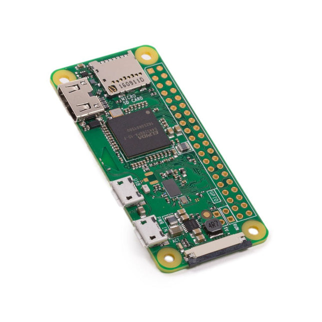
Raspberry Pi Foundation Raspberry Pi Zero W
The Raspberry Pi Zero W extends the Raspberry Pi Zero family. The Raspberry Pi Zero W has all the functionality of the original Raspberry Pi Zero, but comes with added connectivity consisting of: 802.11 b/g/n wireless LAN Bluetooth 4.1 Bluetooth Low Energy (BLE) Other Features 1 GHz, single-core CPU 512 MB RAM Mini HDMI and USB On-The-Go ports Micro-USB power HAT-compatible 40-pin header Composite video and reset headers CSI camera connector Downloads Mechanical Drawing Schematics
-

FNIRSI FNIRSI HRM-10 Battery Internal Resistance & Voltage Tester
The FNIRSI HRM-10 is a portable, high-precision battery internal resistance and voltage tester. This device offers true four-wire measurement and is designed for both accuracy and ease of use. It automatically measures internal resistance and voltage values simultaneously, displaying the results on its HD color screen. Users have the option to manually adjust voltage and resistance ranges to suit their needs. The device also includes a sorting mode that automatically filters the good and bad batteries based on user-set thresholds. Additionally, it supports the storage of historical data and allows for exporting measurement records in table format. Features High Measurement Accuracy Tabular Data Export Auto-Evaluate Measurement Results 8 Threshold Settings HD Color Screen Folding Stand 1000 mAh Lithium Battery Specifications Voltage Resistance Measuring range 0-100 V (DC) 0-200 Ω Accuracy ±0.5% ±0.5% Gear Automatic, 1 V, 10 V, 100 V Automatic, 20 mΩ, 200 mΩ, 2 Ω, 20 Ω, 200 Ω Instrument test signal frequency 1 Khz (AC) Rechargeable USB-C (5 V/1 A) Built-in battery 1000 mAh lithium battery User calibration Yes Sorting mode Yes History record Yes Recorded data export Yes Working environment –10°C to +45°C, relative humidity <80% Storage environment –20°C to +80°C, relative humidity <80% Dimensions 158.7 x 80.5 x 28.4 mm Weight 225 g Included 1x FNIRSI HRM-10 Internal Resistance Tester 1x Clip Test Line 1x USB-C data cable 1x Manual Downloads Manual Firmware V0.3
€ 49,95
-
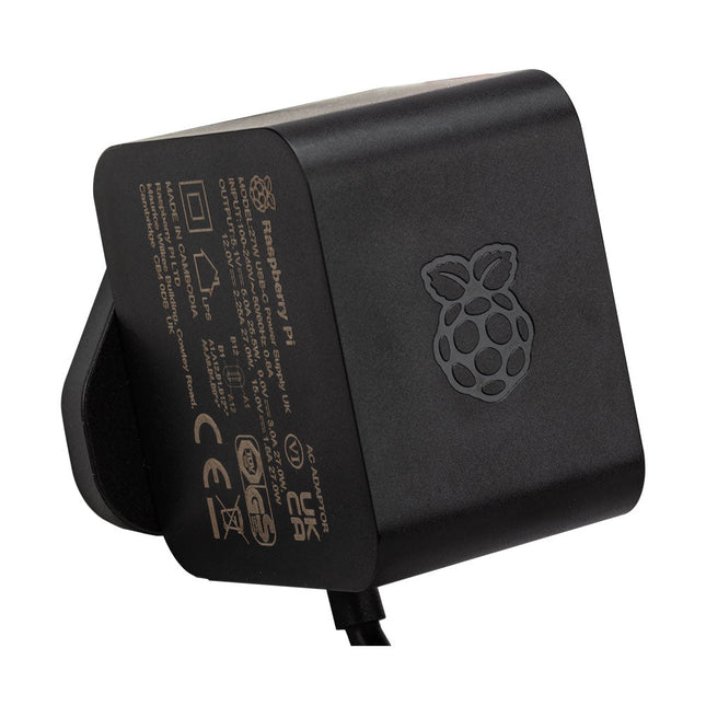
Raspberry Pi Foundation Official 27 W Power Supply for Raspberry Pi 5 (EU, black)
The Raspberry Pi 27 W PD USB-C power supply is designed specifically to power the Raspberry Pi 5. It is also capable of delivering 5 V/3 A, 9 V/3 A, 12 V/2.25 A, 15 V/1.8 A. to PD-compatible products, making it a good and cost-effective power supply for many general applications, such as charging smartphones and tablets. Specifications Input 100-240 VAC Output 5 A @ 5.1 V, 3 A @ 9 V, 2.25 A @ 12 V, 1.8 A @ 15 V Connector USB-C Length 1.2 m Color Black Region EU
-
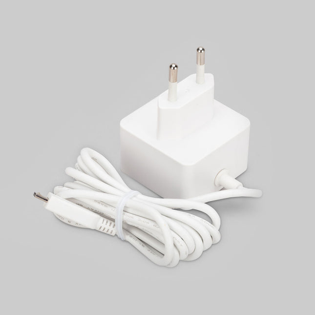
Raspberry Pi Foundation Official Micro-USB Power Supply for Raspberry Pi
Official Micro-USB Power Supply for Raspberry Pi (12.5 W) Input: 100-240 VAC Output: 5.1 V / 2.5 A power supply Connector: micro USB Length: 1.5 m
-
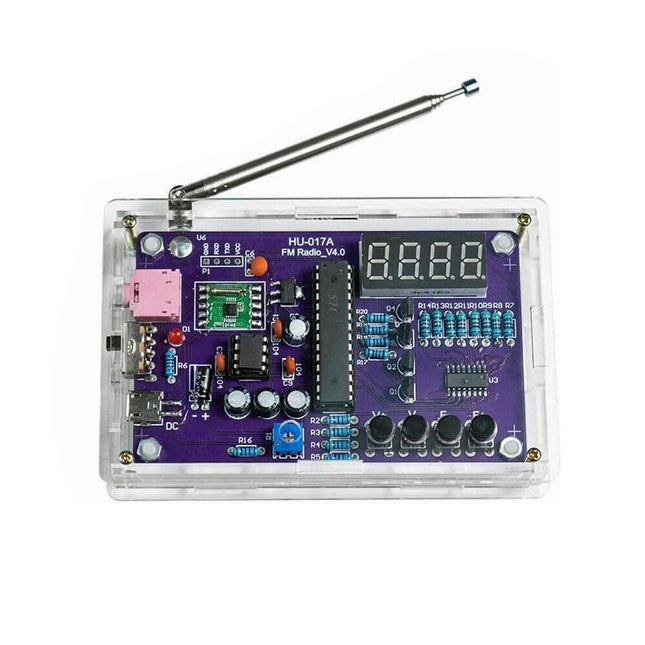
Generic FM Radio Kit
This DIY kit (HU-017A) is a wireless FM radio receiver with a 4-digit 7-segment display. It operates within the global FM receiving frequency band of 87.0-108.0 MHz, making it suitable for use in any country or region. The kit offers two power supply modes, allowing you to use it both at home and outdoors. This DIY electronic product will help you understand circuits and improve your soldering skills. Features 87.0-108.0 MHz FM Radio: Built-in RDA5807 FM data processor with a standard FM receiving frequency band. The FM frequency can be adjusted using the F+ and F- buttons. Adjustable Volume: Two volume adjustment methods – button and potentiometer. There are 15 volume levels. Active & Passive Audio Output: The kit has a built-in 0.5 W power amplifier to drive 8 Ω speakers directly. It also outputs audio signals to headsets or loudspeakers with AUX interfaces, allowing personal listening and sharing of FM audio. Configured with a 25 cm dedicated FM antenna and a (red) 4-digit 7-segment display for real-time display of FM radio frequency. The transparent acrylic shell protects the internal circuit board. It supports dual power supply methods – 5 V USB and 2x 1.5 V (AA) batteries. DIY Hand Soldering: The kit comes with various components that need to be installed manually. It helps exercise and improve soldering skills, making it suitable for electronics hobbyists, beginners, and educational purposes. Specifications Operating voltage DC 3 V/5 V Output impedance 8 Ω Output power 0.5 W Output channel Mono Receiver frequency 87.0 MHz~108.0 MHz Frequency accuracy 0.1 MHz Operating temperature −40°C to +85°C Operating humidity 5% to 95% RH Dimensions 107 x 70 x 23 mm IMPORTANT: Remove the batteries when powering the radio over to USB. Included 1x PCB 1x RDA5807M FM Receiver 1x STC15W404AS MCU 1x IC Socket 1x 74HC595D Register 1x TDA2822M Amplifier 1x IC Socket 1x AMS1117-3.3 V Voltage Converter 18x Metal Film Resistor 1x Potentiometer 4x Ceramic Capacitor 5x Electrolytic Capacitor 4x S8550 Transistor 1x Red LED 1x 4-digit 7-segment Display 1x Toggle Switch 1x SMD Micro USB Socket 1x Radio Antenna 1x AUX Audio Socket 4x Black Button 4x Button Cap 1x 0.5 W/8 Ω Speaker 1x Red/Black Wire 2x Double-sided adhesive 1x AA Battery Box 1x USB cable 6x Acrylic Board 4x Nylon Column Screw 4x M3 Screw 4x M3 Nut 4x M2x22 mm Screw 1x M2x6 mm Screw 5x M2 Nut
-
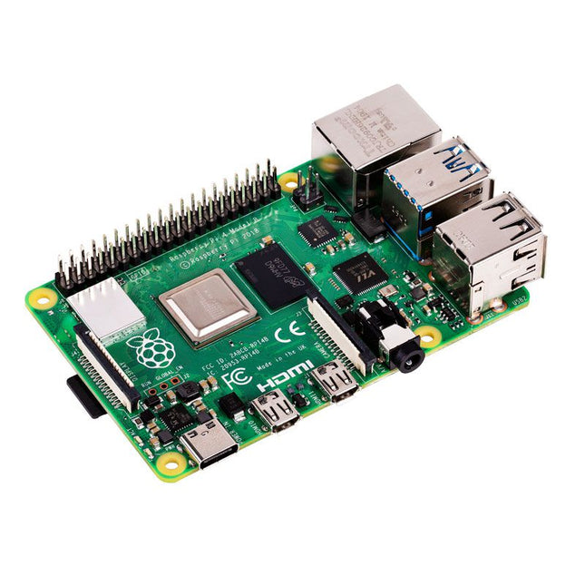
Raspberry Pi Foundation Raspberry Pi 4 B (1 GB RAM)
The Raspberry Pi 4 B is 3x faster than its 3 B+ predecessor and offers 4x faster multimedia performance (comparable to the desktop performance of an entry-level x86-based PC). Features High-performance 64-bit quad-core processor Dual-display support at resolutions up to 4K via a pair of micro-HDMI ports Hardware video decode at up to 4Kp60 Up to 8 GB of RAM Dual-band 2.4/5 GHz wireless LAN Bluetooth 5.0 Gigabit Ethernet USB 3.0 PoE capability (via a separate PoE HAT add-on) Specifications SoC Broadcom BCM2711 CPU 64-bit ARM Cortex-A72 (4x 1.5 GHz) GPU Broadcom VideoCore VI RAM Up to 8 GB LPDDR4 Wireless LAN 2.4 GHz and 5 GHz IEEE 802.11b/g/n/ac wireless LAN Bluetooth Bluetooth 5.0, BLE Ethernet Gigabit Ethernet USB 2x USB-A 3.02x USB-A 2.0 GPIO Standard 40-pin GPIO header (fully backwards-compatible with previous boards) Video 2x micro-HDMI ports (up to 4Kp60 supported)2-lane MIPI DSI port (display)2-lane MIPI CSI port (camera) Audio 4-pole stereo audio and composite video port Multimedia H.265 (4Kp60 decode)H.264 (1080p60 decode, 1080p30 encode)OpenGL ES, 3.0 graphics SD card microSD (for operating system and storage) Power 5 V | 3 A (via USB-C)5 V | 3 A (via GPIO)Power over Ethernet (PoE) enabled – (requires separate PoE HAT) Raspberry Pi 4 B 2 GB RAM 4 GB RAM 8 GB RAM
-
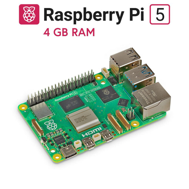
Raspberry Pi Foundation Raspberry Pi 5 (4 GB RAM)
The Raspberry Pi 5 delivers more performance than ever before. Thanks to the faster CPU, GPU and RAM, Raspberry Pi 5 is up to 3x faster than its already fast predecessor. In addition to the speed boost, the Raspberry Pi 5 (which features the new Raspberry Pi RP1 silicon for advanced I/O capabilities) also offers the following features for the first time ever: RTC, an on/off button and a PCIe interface. Features 64-bit quad-core ARM Cortex-A76 processor (2.4 GHz) VideoCore VII GPU (800 MHz) 4 GB of LPDDR4X RAM (4267 MHz) Raspberry Pi silicon RP1 I/O controller chip Real-time clock On/off button PCIe 2.0 UART connector Fan connector Specifications SoC Broadcom BCM2712 CPU ARM Cortex-A76 (ARM v8) 64-bit Clock speed 4x 2.4 GHz GPU VideoCore VII (800 MHz) RAM 4 GB LPDDR4X (4267 MHz) WiFi IEEE 802.11b/g/n/ac (2.4 GHz/5 GHz) Bluetooth Bluetooth 5.0, BLE Ethernet Gigabit Ethernet (with PoE+ support) USB 2x USB-A 3.0 (5 GBit/s)2x USB-A 2.0 PCI Express 1x PCIe 2.0 GPIO Standard 40-pin GPIO header Video 2x micro-HDMI ports (4K60)2x 4-lane MIPI (DSI/CSI) Multimedia H.265 (4K60 decode)OpenGL ES 3.1, Vulkan 1.2 SD card microSD Power 5 V/5 A (via USB-C)Power over Ethernet (PoE+) Raspberry Pi 4 vs Raspberry Pi 5 Raspberry Pi 4 Raspberry Pi 5 SoC Broadcom BCM2711 Broadcom BCM2712 CPU ARM Cortex-A72 (ARM v8) 64-bit ARM Cortex-A76 (ARM v8) 64-bit Clock speed 4x 1.5 GHz 4x 2.4 GHz L2 cache 1 MByte shared 4x 512 KByte L3 cache N/A 2 MByte shared GPU VideoCore VI (500 MHz) VideoCore VII (800 MHz) RAM 4 GB LPDDR4 (3200 MHz) 4 GB LPDDR4X (4267 MHz) WiFi IEEE 802.11b/g/n/ac (2.4 GHz/5 GHz) IEEE 802.11b/g/n/ac (2.4 GHz/5 GHz) Bluetooth Bluetooth 5.0, BLE Bluetooth 5.0, BLE Ethernet Gigabit Ethernet (with PoE support) Gigabit Ethernet (with PoE+ support) USB 2x USB-A 3.02x USB-A 2.0 2x USB-A 3.0 (5 GBit/s)2x USB-A 2.0 I/O controller chip N/A Raspberry Pi Silicon RP1 PCI Express N/A 1x PCIe 2.0 Real Time Clock (RTC) N/A RTC and RTC battery connector On/off button N/A Onboard power button Cooling N/A Fan connector GPIO Standard 40-pin GPIO header Standard 40-pin GPIO header UART via GPIO 1x UART connector SD card microSD slot (DDR50) microSD slot (SDR104) Video 2x micro-HDMI ports (4K60)1x 2-lane MIPI DSI port (display)1x 2-lane MIPI CSI port (camera) 2x micro-HDMI ports (4K60)2x 4-lane MIPI (DSI/CSI) Audio 4-pole 3.5 mm audio jack (stereo audio and composite video) N/A Multimedia H.265 (4K60 decode)H.264 (1080p60 decode, 1080p30 encode)OpenGL ES, 3.0 graphics H.265 (4K60 decode)OpenGL ES 3.1, Vulkan 1.2 Power 5 V/3 A (15 W)Power over Ethernet (PoE) 5 V/5 A (25 W), USB PDPower over Ethernet (PoE+) Raspberry Pi 5 2 GB RAM 8 GB RAM 16 GB RAM Downloads Datasheet Unboxing the Raspberry Pi 5 First Insights
-

FNIRSI FNIRSI LC1020E High Precision LCR Meter
The FNIRSI LC1020E High-Precision LCR Meter with ESR tester is a portable and intelligent solution for testing electronic components, offering a basic accuracy of up to 0.3%. It is ideal for engineers, technicians, and makers. The device supports L/Q, C/D, and R/D measurements using both series and parallel equivalent circuit models, and features a 2.8-inch TFT color display. With preset thresholds and audio-visual alerts, it enables fast pass/fail evaluation, making it perfect for batch testing and quality control. Supporting test frequencies up to 100 kHz, it is well suited for high-frequency analysis of inductors, capacitors, and resistors. Features ±0.05% accuracy with 4.5-digit resolution Automatic R/L/C identification for fast measurements 5 test frequencies (100 Hz–100 kHz) & 3 voltage levels (0.1–0.6 V) Dual display: L/C/R/Z + X/D/Q/θ/ESR Sorting mode & bias voltage for batch testing Dual ports (3-/5-terminal) with 4-wire Kelvin support Data hold & logging for efficient workflow Compact, rechargeable (3000 mAh) – ideal for lab & field use Specifications General Test Frequency 100 Hz, 120 Hz, 1 kHz, 10 kHz, 100 kHz Basic Accuracy 0.3% Display 2.8-inch TFT LCD display Display Digits Main Parameter: 4.5 digits Secondary Parameter: 4.5 digits Measurement Parameters Main Parameters: AUTO/R/C/L/Z Secondary Parameters: X/D/Q/θ/ESR Measurement Range L: 0-100H C: 0-100mF R: 0-10M Internal Bias 0.0 V, 0.5 V Test Level 0.1 V, 0.3 V, 0.6 V Calibration Functions Open circuit calibration, Short circuit calibration Comparison Function Used to calculate the relative error between the component measurement value and the nominal value, displayed as a percentage, and provides filtering results. Nominal values and tolerance can be set, with tolerance range adjustable from 0.1% to 99.9% Function Record Checks if the measured component data meets the set nominal value and tolerance, recording the number of successful and failed measurements Test Terminal Configuration Three-terminal, Five-terminal Output Impedance 100Ω Interface USB-C (Virtual serial port) Others Language settings, Screen brightness, Sound settings, Auto power-off, Calibration settings, System information Battery 3000 mAh Lithium battery Dimensions 18.5 x 8.5 x 3.5 cm Weight 680 g Capacitance (C) Range: 1mF-100mF 100 Hz: 5% ±5 digits 1 kHz: 3% ±5 digits 10 kHz: / 100 kHz: / Range: 1uF-1mF 100 Hz: 1% ±4 digits 1 kHz: 0.5% ±5 digits 10 kHz: 2% ±5 digits 100 kHz: 3% ±4 digits Range: 1nF-1uF 100 Hz: / 1 kHz: 0.3% ±2 digits 10 kHz: 0.4% ±2 digits 100 kHz: 1% ±4 digits Range: 1pF-1nF 100 Hz: / 1 kHz: 2% ±2 digits 10 kHz: 1.5% ±2 digits 100 kHz: 2% ±4 digits Inductance (L) Range: 1H-100H 100 Hz: 2% ±5 digits 1 kHz: 2% ±5 digits 10 kHz: / 100 kHz: / Range: 1mH-1H 100 Hz: 0.4% ±5 digits 1 kHz: 0.3% ±2 digits 10 kHz: 0.4% ±3 digits 100 kHz: 2.5% ±5 digits Range: 10uH-1mH 100 Hz: 3% ±5 digits 1 kHz: 0.5% ±4 digits 10 kHz: 0.5% ±3 digits 100 kHz: 1.5% ±5 digits Range: 1uH-10uH 100 Hz: / 1 kHz: 2% ±5 digits 10 kHz: 2% ±5 digits 100 kHz: 4% ±5 digits Resistance (R) Range: 1MΩ-10MΩ 100 Hz: 5% ±4 digits 1 kHz: 3% ±3 digits 10 kHz: / 100 kHz: / Range: 1KΩ-1MΩ 100 Hz: 0.4% ±4 digits 1 kHz: 0.2% ±2 digits 10 kHz: 0.3% ±3 digits 100 kHz: 0.6% ±5 digits Range: 1Ω-1KΩ 100 Hz: 1.5% ±4 digits 1 kHz: 0.3% ±2 digits 10 kHz: 0.3% ±3 digits 100 kHz: 0.6% ±5 digits Range: 10mΩ-1Ω 100 Hz: 4% ±4 digits 1 kHz: 2% ±5 digits 10 kHz: 2% ±5 digits 100 kHz: 5% ±5 digits Included 1x FNIRSI LC1020E LCR Meter 1x Kelvin Test Clip 2x Test Leads (1x black, 1x red) 1x Shorting Plate 1x USB-C Cable 1x Manual Downloads Manual Firmware V1.1
€ 84,95€ 69,95Best Price
-
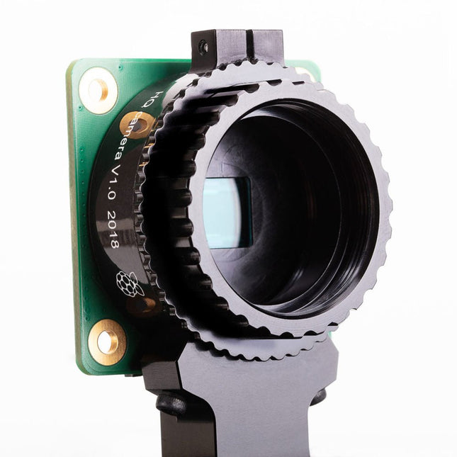
Raspberry Pi Foundation Raspberry Pi High Quality Camera Module
The Raspberry Pi High Quality Camera offers higher resolution (12 megapixels, compared to 8 megapixels), and sensitivity (approximately 50% greater area per pixel for improved low-light performance) than the existing Camera Module v2, and is designed to work with interchangeable lenses in both C and CS Mount form factors. Other lens form factors can be accommodated using third-party lens adapters. Specifications Sensor Sony IMX477R stacked, back-illuminated sensor12.3 megapixels7.9 mm sensor diagonal1.55 x 1.55 μm pixel size Output RAW12/10/8, COMP8 Back focus Adjustable (12.5–22.4 mm) Lens standards CS MountC Mount (C/CS adapter included) IR cut filter Integrated Ribbon cable length 200 mm Tripod mount 1/4”-20 Included 1x Circuit board carrying a Sony IMX477 sensor 1x FPC cable for connection to a Raspberry Pi 1x Milled aluminium lens mount with integrated tripod mount and focus adjustment ring 1x C/CS Mount adapter Required C/CS Mount Lens
-

FNIRSI FNIRSI FNB58 USB Tester (with Bluetooth)
The FNIRSI FNB58 USB tester (with Bluetooth) is a comprehensive and very accurate USB voltage and current meter. It features a 2.0-inch full-color HD TFT display, built-in USB-A, micro USB and USB-C interface. With this device you can measure the power supply or power consumption of products or the charging power of cell phones and power supplies. You can also determine the fast charging protocol of chargers. Features USB-A and USB-C interface 2.0" HD display Data at a glance Wide compatibility Ultra-precise data detection Play with fast charging technology Automatic protocol detection (PD2.0, 3.0, 3.1, PPS, QC2.0, 3.0, FCP, SCP, AFC, PE, DASH VOOC, SuperVOOC and more) Simple user interface, easy to operate 4 function curve displays (real-time voltage and current curve, offline curve recording, D+/D- voltage curve, high-speed power supply ripple measurement) Cable detection 10 groups of energy recording battery capacity calculation PC connectivity for data logging and firmware updates Bluetooth app for Android devices Specifications Voltage range 4-28 V Current range 0-7 A Power range 0-120 W Load equivalent internal resistance 0-9999.9 Ω D+/D- voltage 0-3.3 V Capacity 0-9999.99 Ah Power consumption 0-9999.99 Wh Cable resistance 0-9999.9 Ω Interfaces micro USB, USB-A, USB-C Dimensions 42 x 13 x 82 mm Downloads Manual Firmware V0.68
€ 49,95
-
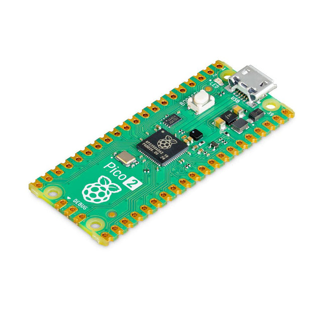
Raspberry Pi Foundation Raspberry Pi Pico 2
The Raspberry Pi Pico 2 is a new microcontroller board from the Raspberry Pi Foundation, based on the RP2350. It features a higher core clock speed, double the on-chip SRAM, double the on-board flash memory, more powerful Arm cores, optional RISC-V cores, new security features, and upgraded interfacing capabilities. The Raspberry Pi Pico 2 offers a significant boost in performance and features while maintaining hardware and software compatibility with earlier members of the Raspberry Pi Pico series. The RP2350 provides a comprehensive security architecture built around Arm TrustZone for Cortex-M. It incorporates signed boot, 8 KB of antifuse OTP for key storage, SHA-256 acceleration, a hardware TRNG, and fast glitch detectors. The unique dual-core, dual-architecture capability of the RP2350 allows users to choose between a pair of industry-standard Arm Cortex-M33 cores and a pair of open-hardware Hazard3 RISC-V cores. Programmable in C/C++ and Python, and supported by detailed documentation, the Raspberry Pi Pico 2 is the ideal microcontroller board for both enthusiasts and professional developers. Specifications CPU Dual Arm Cortex-M33 or dual RISC-V Hazard3 processors @ 150 MHz Memory 520 KB on-chip SRAM; 4 MB on-board QSPI flash Interfaces 26 multi-purpose GPIO pins, including 4 that can be used for AD Peripherals 2x UART 2x SPI controllers 2x I²C controllers 24x PWM channels 1x USB 1.1 controller and PHY, with host and device support 12x PIO state machines Input power 1.8-5.5 V DC Dimensions 21 x 51 mm Downloads Datasheet (Pico 2) Datasheet (RP2350)
-
Raspberry Pi Foundation Official Case for Raspberry Pi 4 (black/gray)
Official Case for Raspberry Pi 4 (black/gray)
-

Raspberry Pi Foundation Raspberry Pi Debug Probe
The Raspberry Pi Debug Probe is an all-in-one USB-to-debug kit that provides all the necessary hardware and cables for easy, solderless, plug-and-play debugging. It features both a processor serial debug interface (by default the ARM Serial Wire Debug interface, but other interfaces can be supported) and an industry-standard UART interface. Both interfaces use the Raspberry Pi 3-pin debug connector. It is designed to make it easy to debug and program Raspberry Pi Pico and RP2040 with a range of host platforms including Windows, Mac, and typical Linux computers. While designed for use with Raspberry Pi products, the Debug Probe provides standard UART and CMSIS-DAP interfaces over USB, so it can also be used with other processors, or even just as a USB-to-UART cable. It works with OpenOCD and other tools that support CMSIS-DAP. The Debug Probe is based on Raspberry Pi Pico hardware and runs the open source Raspberry Pi Pico Probe software. The firmware is updated in the same way as Raspberry Pi Pico firmware, so it is easy to keep the unit up to date with the latest firmware, or to use custom firmware. Features USB to ARM Serial Wire Debug (SWD) port USB to UART bridge Compatible with the CMSIS-DAP standard Works with OpenOCD and other tools supporting CMSIS-DAP Open source, easily upgradeable firmware Specifications Dimensions: 22 x 32 mm Nominal I/O voltage: 3.3 V Operating temperature: -20°C to +70°C Included 1x Raspberry Pi Debug Probe 1x Plastic case 1x USB cable 3x Debug cables 3-pin JST connector to 3-pin JST connector cable 3-pin JST connector to 0.1-inch header (female) 3-pin JST connector to 0.1-inch header (male) Downloads Datasheet 3-pin Debug Connector Schematics Diagram Latest Firmware
-

Generic LC Meter Kit
This LC meter kit is an easy-to-build, educational, and entertaining DIY project for measuring the inductance (L) of coils and inductors, the capacitance (C) of capacitors, other passive components and the frequency of signals. Specifications Power supply USB DC 5 V Capacitance measurement range of small non-polarized capacitors 1 pF~2200 pF Capacitance measurement range of electrolytic capacitors 1 µF~12000 µF Inductance measurement range 1 µH~1 H Frequency measurement range 20 Hz~400 kHz Dimensions (PCB) 91 x 80 mm Dimensions (Shell) 106 x 91 x 28 mm Included Doubled-sided PCB All required components incl. LCD display Six pre-cut transparent acrylic plates Screws and nuts
-
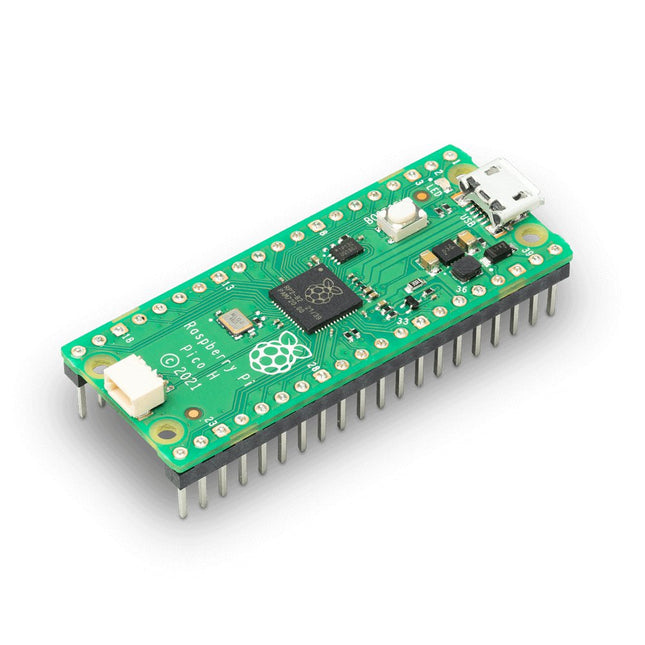
Raspberry Pi Foundation Raspberry Pi Pico H
Raspberry Pi Pico is a low-cost, high-performance microcontroller board and also the first product based on a chip developed by Raspberry Pi itself. The RP2040 microcontroller chip ('Raspberry Silicon') offers a dual-core ARM Cortex-M0+ processor (133 MHz), 256 KB RAM, 30 GPIO pins, and many other interface options. In addition, there is 2 MB of on-board QSPI flash memory for code and data storage. Specifications RP2040 microcontroller chip designed by Raspberry Pi in the UK Dual-core ARM Cortex M0+ processor, with a flexible clock running up to 133 MHz 264 kB SRAM, and 2 MB on-board Flash memory Castellated module allows soldering directly to carrier boards USB 1.1 host and device support Energy-efficient sleep and dormant modes Drag and drop programming using mass storage via USB 26x multifunction GPIO pins 2x SPI, 2x I²C, 2x UART, 3x 12-bit ADC, 16x controllable PWM channels On-chip accurate clock and timer Temperature sensor On-chip accelerated floating point libraries 8x programmable IO (PIO) state machines for custom peripherals H version of the Raspberry Pi Pico board with pre-soldered headers and 3-pin debug connector Downloads Specifications of 3-pin Debig Connector
-
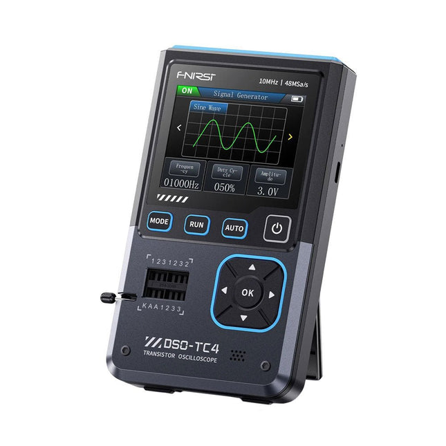
FNIRSI FNIRSI DSO-TC4 (3-in-1) Oscilloscope (10 MHz) + Transistor Tester + Signal Generator
The FNIRDSI DSO-TC4 is a multifunctional transistor oscilloscope that is both comprehensive and practical. It is designed for use in maintenance and R&D applications, integrating an oscilloscope, transistor tester, and signal generator into a single device. Features Equipped with a 2.8-inch TFT color screen for a clear and intuitive display Built-in high-capacity rechargeable lithium battery (1500 mAh) with a standby time of up to 4 hours Compact and lightweight, ideal for mobile use Specifications Oscilloscope Analog Bandwidth 10 MHz Real-Time Sampling Rate 48 MSa/s Input Impedance 1 MΩ Coupling Mode AC/DC Test Voltage Range 1:1 Probe: 80 Vpp (+40 V) 10:1 Probe: 800 Vpp (+400 V) Vertical Sensitivity 10 mV/div~10 V/div (X1 range) Vertical Displacement Adjustable with indication Time Base Range 50ns~20s Trigger Mode Auto/Normal/Single Trigger Type Rising edge, Falling edge Trigger Level Adjustable with indication Waveform Freeze Yes (HOLD function) Automatic Measurement Max, Min, Avg, RMS, Vpp, Frequency, Cycle, Duty Cycle Component Tester Transistor Amplification factor "hfe"; Base-Emitter voltage "Ube", Ic/Ie, Collector-Emitter reverse leakage current "Iceo", Ices, Forward voltage drop of protection diode "Uf" Diode Forward voltage drop <5 V (Forward voltage drop, Junction capacitance, Reverse leakage current) Zener Diode 0.01~32 V Reverse Breakdown Voltage (K-A-A Test Area) Field-Effect Transistor (FET) JFET: Gate capacitance "Cg", Drain current Id under "Vgs", Forward voltage drop of protection diode "Uf" IGBT: Drain current Id under Vgs, Forward voltage drop of protection diode Uf MIOSTET: Threshold voltage "Vt", Gate capacitance "Cg", Drain-Source resistance "Rds", Forward voltage drop of protection diode "Uf" Unidirectional SCR Trigger voltage <5V, Gate level (Gate voltage) Bidirectional SCR Trigger current <6mA (Gate voltage) Capacitor 25pF~100mF, Capacitance value, Loss factor "Vloss" Resistor 0.01Ω~50MΩ Inductor 10μH~1000μH, DC resistance DS18B20 Temperature sensor, Pins: GND, DQ, VDD DHT11 Temperature and humidity sensor, Pins: VDD, DATA, GND Signal Generator Output Waveform Supports 13 waveform outputs Waveform Frequency 0-50 KHz Square Wave Duty Cycle 0-100% Waveform Amplitude 0.1-3.0 V General Display 2.8-inch TFT color screen Backlight Brightness adjustable Power Supply USB-C (5 V/1 A) Battery 3.7 V/1500 mAh Languages English, German, Spanish, Portuguese, Russian, Chinese, Japanese, Korean Dimensions 90 x 142 x 27.5 mm Weight 186 g Included 1x FNIRSI DSO-TC4 (3-in-1) Oscilloscope (10 MHz) 1x P6100 Oscilloscope probes (10X) 1x Alligator clip probe 3x Test hooks 1x Adapter 1x USB-C charging cable 1x Manual Downloads Manual Firmware V0.0.7 (+V1.0.9)
€ 89,95€ 74,95Best Price
-

Raspberry Pi Foundation Official Raspberry Pi USB-C Adapter (black)
This small adapter allows you to convert an existing micro USB power supply into a USB-C power supply.
-
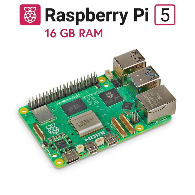
Raspberry Pi Foundation Raspberry Pi 5 (16 GB RAM)
The Raspberry Pi 5 delivers more performance than ever before. Thanks to the faster CPU, GPU and RAM, Raspberry Pi 5 is up to 3x faster than its already fast predecessor. In addition to the speed boost, the Raspberry Pi 5 (which features the new Raspberry Pi RP1 silicon for advanced I/O capabilities) also offers the following features for the first time ever: RTC, an on/off button and a PCIe interface. Features 64-bit quad-core ARM Cortex-A76 processor (2.4 GHz) VideoCore VII GPU (800 MHz) 16 GB of LPDDR4X RAM (4267 MHz) Raspberry Pi silicon RP1 I/O controller chip Real-time clock On/off button PCIe 2.0 UART connector Fan connector Specifications SoC Broadcom BCM2712 CPU ARM Cortex-A76 (ARM v8) 64-bit Clock speed 4x 2.4 GHz GPU VideoCore VII (800 MHz) RAM 16 GB LPDDR4X (4267 MHz) WiFi IEEE 802.11b/g/n/ac (2.4 GHz/5 GHz) Bluetooth Bluetooth 5.0, BLE Ethernet Gigabit Ethernet (with PoE+ support) USB 2x USB-A 3.0 (5 GBit/s)2x USB-A 2.0 PCI Express 1x PCIe 2.0 GPIO Standard 40-pin GPIO header Video 2x micro-HDMI ports (4K60)2x 4-lane MIPI (DSI/CSI) Multimedia H.265 (4K60 decode)OpenGL ES 3.1, Vulkan 1.2 SD card microSD Power 5 V/5 A (via USB-C)Power over Ethernet (PoE+) Raspberry Pi 5 2 GB RAM 4 GB RAM 8 GB RAM Downloads Datasheet Unboxing the Raspberry Pi 5 First Insights
-

QuantAsylum QuantAsylum QA403 24-bit Audio Analyzer
The QA403 is QuantAsylum's fourth-generation audio analyzer. The QA403 extends the functionality of the QA402 with improved noise and distortion performance, in addition to a flatter response at band edges. The compact size of the QA403 means you can take it just about anywhere. Features 24-bit ADC/DAC Up to 192 kS/s Fully isolated from PC Differential Input/Output USB powered Built-in Attenuator Fast Bootup and Driverless The QA403 is a driverless USB device, meaning it’s ready as soon as you plug it in. The software is free and it is quick and easy to move the hardware from one machine to the next. So, if you need to head to the factory to troubleshoot a problem or take the QA403 home for a work-from-home day, you can do it without hassle. No-Cal Design The QA403 comes with a factory calibration in its flash memory, ensuring consistent unit-to-unit performance. On your manufacturing line you can install another QA403 and be confident what you read on one unit will be very similar to the next unit. It is not expected that re-calibration will be required at regular intervals. Measurements Making basic measurements is quick and easy. In a few clicks you will understand the frequency response, THD(+N), gain, SNR and more of your device-under test. Dynamic Range The QA403 offers 8 gain ranges on the input (0 to +42 dBV in 6 steps), and 4 gain ranges on the output (-12 to +18 dBV in 10 dB steps). This ensures consistent performance over very wide ranges of input and output levels. The maximum AC input to the QA403 is +32 dBV = 40 Vrms. The maximum DC is ±40 V, and the maximum ACPEAK + DC = ±56 V. Easy Programmability The QA403 supports a REST interface, making it easy to automate measurements in just about any language you might anticipate. From Python to C++ to Visual Basic—if you know how to load a web page in your favorite language, you can control the QA403 remotely. Measurements are fast and responsive, usually with dozens of commands being processed per second. Isolated and USB Powered The QA403 is isolated from the PC, meaning you are measuring your DUT and not chasing some phantom ground loop. The QA403 is USB powered, like nearly all our instruments. If you are setting up remotely, throw a powered hub in your bag and your entire test setup can be running with a minimum of cables. Goodbye Soundcard, Hello QA403 Tired of trying to make a soundcard work? The calibration nightmare? The lack of gain stages? The limited drive? Are you tired of dealing with the fixed input ranges? The worry that you might destroy it with too much DC or AC? Tired of the ground loops? That’s why QuantAsylum built the QA403. Specifications Dimensions 177 x 44 x 97 mm (W x H x D) Weight 435 g Case Material Powder-coating Aluminum (2 mm thick front panel, 1.6 mm thick top/bottom) Downloads Datasheet Manual GitHub
-
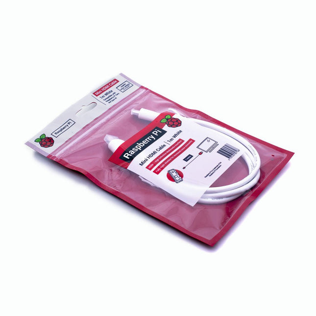
Raspberry Pi Foundation Official Mini-HDMI Cable for Raspberry Pi Zero
The official Raspberry Pi mini-HDMI to HDMI (A/M) cable designed for all Raspberry Pi Zero models. 19-pin HDMI Type D(M) to 19-pin HDMI Type A(M) 1 m cable (white) Nickel-plated plugs 4Kp60 compliant RoHS compliant 3 Mohm 300 VDC insulation, withstands 300 VDC for 0.1s
€ 3,95€ 1,95Best Price
-

Zhongdi ZD-153A Solder Fume Extractor
Fumes released during the soldering process are potentially harmful to health. This solder fume extractor is securely fastened to the work table with a bracket. Thanks to the 3 axes, the solder fume extractor can be positioned perfectly, i.e. directly above the rising solder fumes. The harmful solder fumes are extracted by a powerful but quiet fan and filtered by an activated-carbon filter mat. Features Removes solder fumes Absorbs toxic gases and fumes from brazing operations Helps reduce the likelihood of headaches, eye irration and neusea Adjustable absorption angle for accurate placement Easy replaceable activated carbon filter High-performance fan Low noise and long life service Specifications Absorption capacity: 1 m³/min (max.) Power consumption: 23 W Power supply: 220-240 VAC Amount of activated carbon filter: 7 g Maximum absorption weight: 2 g Dimensions: 220 x 270 x 168 mm (W x H x D) Weight: 1.4 kg
€ 52,95
-
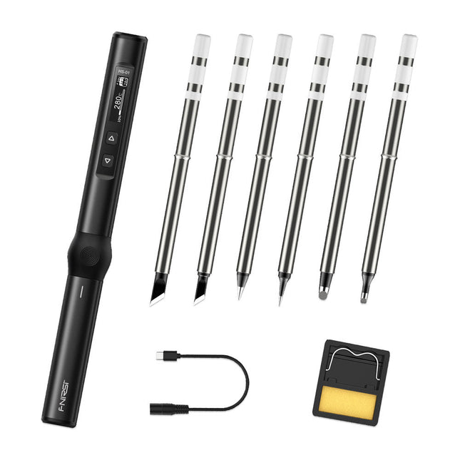
FNIRSI FNIRSI HS-01 Smart Soldering Iron (incl. 6 Soldering Tips)
The perfect tool for quick repairs The FNIRSI HS-01 is a powerful, adjustable smart soldering iron with a built-in 0.87-inch OLED display that quickly reaches temperatures between 80-420°C (180-780°F). The display shows all important information, including the status of the temperature level, the set temperature, the supply voltage and the power percentage. You can set the input voltage from 9-20 V directly in the menu according to your needs. The integrated sleep mode automatically turns off the iron after 30 minutes. Features 96 W input (DC) 65 W PD power OLED display Constant temperature & fast heating CNC metal integral molding Smart safety anti-scald Mini pocket size Ergonomic design Aluminum material Left/right hand switch Efficient heat radiation Inductive sleep Color: Black Specifications Power 65 W Screen 0.87" OLED Operating voltage 9-20 VDC Power supply USB-C Temperature range 80-420°C (180-780°F) Fast charging protocol PD trigger Dimensions 184 x 20 x 20 mm (7.24 x 0.79 x 0.79') Weight 56 g Power Selection Operating voltage 20 V 15 V 12 V 9 V Operating current ≥3.25 A ≥2.5 A ≥2 A ≥1.5 A Power 65 W 37.5 W 24 W 13.5 W Tin melting time 8s 12s 17s 30s Included 1x FNRISI HS-01 smart soldering iron 6x Soldering iron tips (HS01-BC2, HS01-KR, HS01-K65, HS01-B2, HS01-ILS, HS01-BC3) 1x DC to USB-C power cable 1x Mini soldering iron stand 1x Manual Required Power adapter USB-C cable Downloads Manual Firmware V0.3.s19
€ 82,00
-
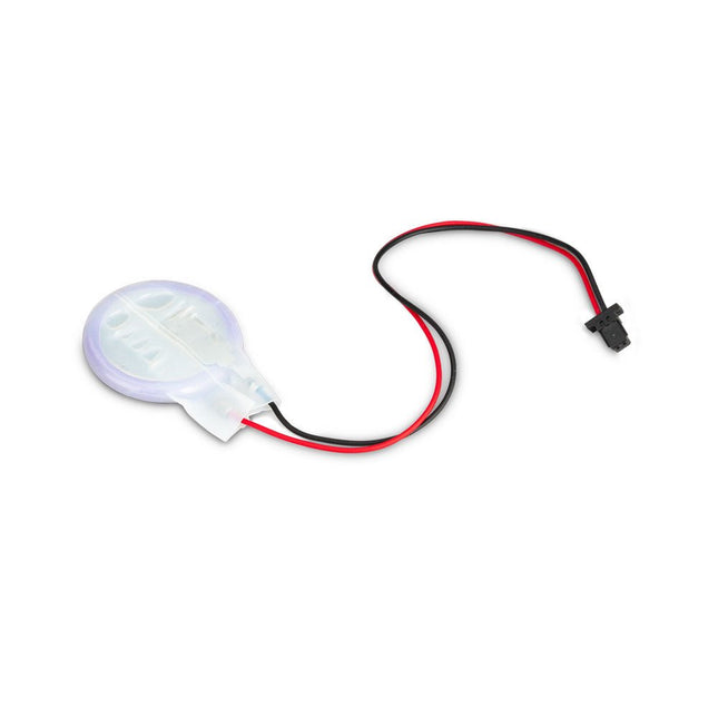
Raspberry Pi Foundation RTC Battery for Raspberry Pi 5
The power-management IC used on Raspberry Pi 5 integrates a real-time clock, and charging circuitry for a button cell which can power the clock while main power is disconnected. This Panasonic ML-2020 lithium manganese dioxide battery with a two-pin plug and a double-sided adhesive pad can be connected directly to the battery connector of the Raspberry Pi 5 and attached to the inside of a case or another convenient location.
-
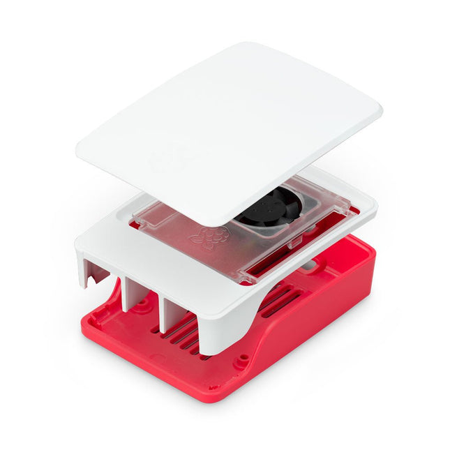
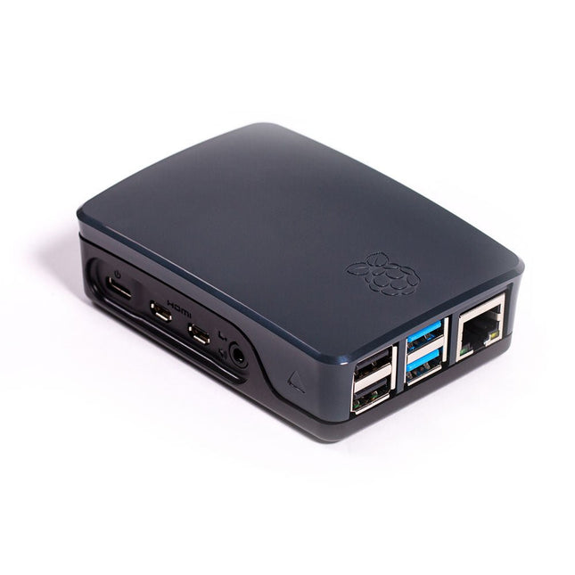
Raspberry Pi Foundation Official Case for Raspberry Pi 5 (white/red)
The Raspberry Pi 5 case is a refinement of the Raspberry Pi 4 case with improved thermal features to support the higher peak power consumption of the Raspberry Pi 5. It integrates a variable speed fan that is powered and controlled via a dedicated connector on the Raspberry Pi 5.


