Inventor 2040 W is a multi-talented board that does (almost) everything you might want a robot, prop or other mechanical thing to do. Drive a couple of fancy motors with encoders attached? Yep! Add up to six servos? Sure? Attach a little speaker so you can make noise? No problem! It's also got a battery connector so you can power your inventions from AA/AAA or LiPo batteries and carry your miniature automaton/animated top hat/treasure chest that growls at your enemies around with you untethered.
You also get a ton of options for hooking up sensors and other gubbins – there's two Qw/ST connectors (and an unpopulated Breakout Garden slot) for attaching breakouts, three ADC pins for analog sensors, photoresistors and such, and three spare digital GPIO you could use for LEDs, buttons or digital sensors. Speaking of LEDs, the board features 12 addressable LEDs (AKA Neopixels) – one for each servo and GPIO/ADC channel.
Features
Raspberry Pi Pico W Aboard
Dual Arm Cortex M0+ running at up to 133 Mhz with 264 kB of SRAM
2 MB of QSPI flash supporting XiP
Powered and programmable by USB micro-B
2.4 GHz wireless
2 JST-SH connectors (6 pin) for attaching motors
Dual H-Bridge motor driver (DRV8833)
Per motor current limiting (425 mA)
Per motor direction indicator LEDs
2 pin (Picoblade-compatible) connector for attaching speaker
JST-PH (2 pin) connector for attaching battery (input voltage 2.5-5.5 V)
6 sets of header pins for connecting 3 pin hobby servos
6 sets of header pins for GPIO (3 of which are ADC capable)
12x addressable RGB LEDs/Neopixels
User button
Reset button
2x Qw/ST connectors for attaching breakouts
Unpopulated headers for adding a Breakout Garden slot
Fully assembled
No soldering required (unless you want to add the Breakout Garden slot).
C/C++ and MicroPython libraries
Schematic
Downloads
Download pirate-brand MicroPython
Getting Started with Raspberry Pi Pico
Motor function reference
Servo function reference
MicroPython examples
C++ examples
After power on, YDLIDAR G4 start rotating and scanning the environment around it. The scanning distance is 16 m and the device offers a scanning rate of 9,000 times per second.
It makes detailed examinations of its environment and can locate the smallest of objects surrounding it. Featuring a high-precision brushless motor and encoder disc mounted on bearings, it rotates smoothly and has a service life of up to 500,000 hours of operation.
The G4 is an inexpensive solution for projects that require obstacle detection, obstacle avoidance, and/or simultaneous localization and mapping (SLAM). All YDLIDAR products are ROS ready.
Features
360 degree 2D range scanning
Stable performance, high precision
16 m range
Strong resistance to environmental light interference
Brushless motor drive, stable performance
FDA Laser safety standard Class I
360 degree omnidirectional scanning, 5-12 Hz adaptive scanning frequency
OptoMagnetic technology
Wireless data communication
Scanning rate of 9000 Hz
Downloads
Datasheet
User Manual
Development Manual
SDK
Tool
ROS
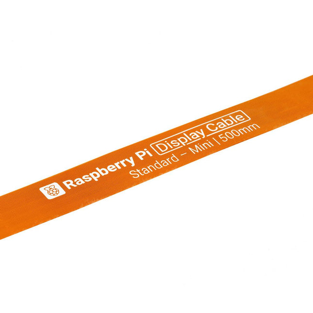
Raspberry Pi 5 provides two four-lane MIPI connectors, each of which can support either a camera or a display. These connectors use the same 22-way, 0.5 mm-pitch “mini” FPC format as the Compute Module Development Kit, and require adapter cables to connect to the 15-way, 1 mm-pitch “standard” format connectors on current Raspbery Pi camera and display products.These mini-to-standard adapter cables for cameras and displays (note that a camera cable should not be used with a display, and vice versa) are available in 200 mm, 300 mm and 500 mm lengths.
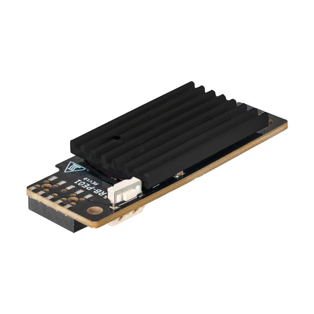
Wide Range Power Supply for Raspberry Pi
With the PiEnergy Mini, you can operate your Raspberry Pi with a voltage of 6 to 36 V DC. You can use the button integrated on the board to both power up and power down your Raspberry Pi.
Communication with the Raspberry Pi is via GPIO4, but this connection can also be cut by removing a resistor to use the pin freely. Thanks to the ultra-flat design, it can also be used in many housings. The pin header is included and not soldered on to keep the design even flatter.
Specifications
Input voltage
6 to 36 V DC
Output voltage
5.1 V
Output current
Up to 3 A (active ventilation recommended for additionally connected loads)
Cable cross-section at the power input
0.2-0.75 mm²
Interface to the Raspberry Pi
GPIO4
Microcontroller
ATtiny5
Further connections
5 V fan connector (2-pin/2.54 mm)Solder pads for external on/off switch
Compatible with
Raspberry Pi 3, 4, 5
Dimensions
23 x 56 x 11 mm
Included
Board with mounted heat sink
Pin header (2x5)
Spacer, screw, nut
Downloads
Datasheet (English)
Datasheet (Italiano)
Manual (English)
Manual (Italiano)
The SparkFun Thing Plus Matter is the first easily accessible board of its kind that combines Matter and SparkFun’s Qwiic ecosystem for agile development and prototyping of Matter-based IoT devices. The MGM240P wireless module from Silicon Labs provides secure connectivity for both 802.15.4 with Mesh communication (Thread) and Bluetooth Low Energy 5.3 protocols. The module comes ready for integration into Silicon Labs' Matter IoT protocol for home automation.
What is Matter? Simply put, Matter allows for consistent operation between smart home devices and IoT platforms without an Internet connection, even from different providers. In doing so, Matter is able to communicate between major IoT ecosystems in order to create a single wireless protocol that is easy, reliable, and secure to use.
The Thing Plus Matter (MGM240P) includes Qwiic and LiPo battery connectors, and multiple GPIO pins capable of complete multiplexing through software. The board also features the MCP73831 single-cell LiPo charger as well as the MAX17048 fuel gauge to charge and monitor a connected battery. Lastly, a µSD card slot for any external memory needs is integrated.
The MGM240P wireless module is built around the EFR32MG24 Wireless SoC with a 32-bit ARM Cortext-M33 core processor running at 39 MHz with 1536 kb Flash memory and 256 kb RAM. The MGM240P works with common 802.15.4 wireless protocols (Matter, ZigBee, and OpenThread) as well as Bluetooth Low Energy 5.3. The MGM240P supports Silicon Labs' Secure Vault for Thread applications.
Specifications
MGM240P Wireless Module
Built around the EFR32MG24 Wireless SoC
32-bit ARM-M33 Core Processor (@ 39 MHz)
1536 kB Flash Memory
256 kB RAM
Supports Multiple 802.15.4 Wireless Protocols (ZigBee and OpenThread)
Bluetooth Low Energy 5.3
Matter-ready
Secure Vault Support
Built-in Antenna
Thing Plus Form-Factor (Feather-compatible):
Dimensions: 5.8 x 2.3 cm (2.30 x 0.9')
2 Mounting Holes:
4-40 screw compatible
21 GPIO PTH Breakouts
All pins have complete multiplexing capability through software
SPI, I²C and UART interfaces mapped by default to labeled pins
13 GPIO (6 labeled as Analog, 7 labeled for GPIO)
All function as either GPIO or Analog
Built-in-Digital to Analog Converter (DAC)
USB-C Connector
2-Pin JST LiPo Battery Connector for a LiPo Battery (not included)
4-Pin JST Qwiic Connector
MC73831 Single-Cell LiPo Charger
Configurable charge rate (500 mA Default, 100 mA Alternate)
MAX17048 Single-Cell LiPo Fuel Gauge
µSD Card Slot
Low Power Consumption (15 µA when MGM240P is in Low Power Mode)
LEDs:
PWR – Red Power LED
CHG – Yellow battery charging status LED
STAT – Blue status LED
Reset Button:
Physical push-button
Reset signal can be tied to A0 to enable use as a peripheral device
Downloads
Schematic
Eagle Files
Board Dimensions
Hookup Guide
Datasheet (MGM240P)
Fritzing Part
Thing+ Comparison Guide
Qwiic Info Page
GitHub Hardware Repo
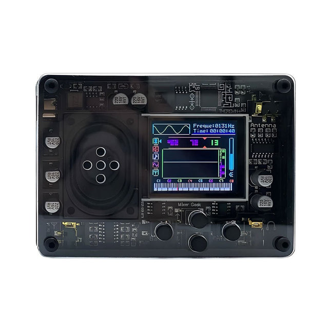
The Mixer Geek Theremin+ is a fun and innovative electronic musical instrument inspired by the classic Theremin. Unlike traditional instruments, the Theremin+ is played without physical contact, using hand movements in the air to control pitch and volume.
The Theremin+ offers an exciting and hands-on way to explore music and sound experimentation.
Features
Ready to use out of the box
Equipped with a loudspeaker and full-color screen
Intuitive button-based navigation and confirmation
Choose from over 70 tones
Multiple customizable function settings
Displays waveform, time, frequency, volume, and corresponding piano pitch (display can be turned off)
Powered via USB-C port; compatible with power banks
Compact design with removable telescopic antenna for easy storage
Connects to headphones, external speakers, or recording devices
Dimensions: 98 x 70 x 18 mm
Included
1x Theremin+ Musical Instrument
2x Antennas
1x USB-C cable
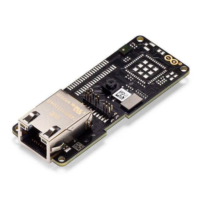
The Arduino Pro Portenta Vision Shield brings industry-rated features to your Portenta. This hardware add-on will let you run embedded computer vision applications, connect wirelessly or via Ethernet to the Arduino Cloud or your own infrastructure, and activate your system upon the detection of sound events.
Features
324x324 pixels camera sensor: use one of the cores in Portenta to run image recognition algorithms using the OpenMV for Arduino editor
100 Mbps Ethernet connector: get your Portenta H7 connected to the wired Internet
2 onboard microphones for directional sound detection: capture and analyse sound in real-time
JTAG connector: perform low-level debugging of your Portenta board or special firmware updates using an external programmer
SD-Card connector: store your captured data in the card, or read configuration files
The Vision Shield has been designed to fit on top of the Arduino Portenta family. The Portenta boards feature multicore 32-bit ARM Cortex processors running at hundreds of megahertz, with megabytes of program memory and RAM. Portenta boards come with WiFi and Bluetooth.
Embedded Computer Vision Made Easy
Arduino has teamed up with OpenMV to offer you a free license to the OpenMV IDE, an easy way into computer vision using MicroPython as a programming paradigm. Download the OpenMV for Arduino Editor from our professional tutorials site and browse through the examples we have prepared for you inside the OpenMV IDE. Companies across the whole world are already building their commercial products based on this simple-yet-powerful approach to detect, filter, and classify images, QR codes, and others.
Debugging With Professional Tools
Connect your Portenta H7 to a professional debugger through the JTAG connector. Use professional software tools like the ones from Lauterbach or Segger on top of your board to debug your code step by step. The Vision Shield exposes the required pins for you to plug in your external JTAG.
Camera
Himax HM-01B0 camera module
Resolution
320 x 320 active pixel resolution with support for QVGA
Image sensor
High sensitivity 3.6μ BrightSense pixel technology
Microphone
2 x MP34DT05
Length
66 mm
Width
25 mm
Weight
11 gr
For more information, check out the tutorials provided by Arduino here.
The EC200U-EU C4-P01 development board features the EC200U-EU LTE Cat 1 wireless communication module, offering a maximum data rate of up to 10 Mbps for downlink and 5 Mbps for uplink. It supports multi-mode and multi-band communication, making it a cost-effective solution.
The board is designed in a compact and unified form factor, compatible with the Quectel multi-mode LTE Standard EC20-CE. It includes an onboard USB-C port, allowing for easy development with just a USB-C cable.
Additionally, the board is equipped with a 40-pin GPIO header that is compatible with most Raspberry Pi HATs.
Features
Equipped with EC200U-EU LTE Cat 1 wireless communication module, multi-mode & multi-band support
Onboard 40-Pin GPIO header, compatible with most Raspberry Pi HATs
5 LEDs for indicating module operating status
Supports TCP, UDP, PPP, NITZ, PING, FILE, MQTT, NTP, HTTP, HTTPS, SSL, FTP, FTPS, CMUX, MMS protocols, etc.
Supports GNSS positioning (GPS, GLONASS, BDS, Galileo, QZSS)
Onboard Nano SIM card slot and eSIM card slot, dual card single standby
Onboard MIPI connector for connecting MIPI screen and is fully compatible with Raspberry Pi peripherals
Onboard camera connector, supports customized SPI cameras with a maximum of 300,000 pixels
Provides tools such as QPYcom, Thonny IDE plugin, and VSCode plugin, etc. for easy learning and development
Comes with online development resources and manual (example in QuecPython)
Specifications
Applicable Regions
Europe, Middle East, Africa, Australia, New Zealand, Brazil
LTE-FDD
B1, B3, B5, B7, B8, B20, B28
LTE-TDD
B38, B40, B41
GSM / GPRS / EDGE
GSM: B2, B3, B5, B8
GNSS
GPS, GLONASS, BDS, Galileo, QZSS
Bluetooth
Bluetooth 4.2 (BR/EDR)
Wi-Fi Scan
2.4 GHz 11b (Rx)
CAT 1
LTE-FDD: DL 10 Mbps; UL 5 Mbps
LTE-TDD: DL 8.96 Mbps; UL 3.1 Mbps
GSM / GPRS / EDGE
GSM: DL 85.6 Kbps; UL 85.6 Kbps
USB-C Port
Supports AT commands testing, GNSS positioning, firmware upgrading, etc.
Communication Protocol
TCP, UDP, PPP, NITZ, PING, FILE, MQTT, NTP, HTTP, HTTPS, SSL, FTP, FTPS, CMUX, MMS
SIM Card
Nano SIM and eSIM, dual card single standby
Indicator
P01: Module Pin 1, default as EC200A-XX PWM0
P05: Module Pin 5, NET_MODE indicator
SCK1: SIM1 detection indicator, lights up when SIM1 card is inserted
SCK2: SIM2 detection indicator, lights up when SIM2 card is inserted
PWR: Power indicator
Buttons
PWK: Power ON/OFF
RST: Reset
BOOT: Forcing into firmware burning mode
USB ON/OFF: USB power consumption detection switch
Antenna Connectors
LTE main antenna + DIV / WiFi (scanning only) / Bluetooth antenna + GNSS antenna
Operating Temperature
−30~+75°C
Storage Temperature
−45~+90°C
Downloads
Wiki
Quectel Resources
At the core of this module is ESP32-S2, an Xtensa® 32-bit LX7 CPU that operates at up to 240 MHz. The chip has a low-power co-processor that can be used instead of the CPU to save power while performing tasks that do not require much computing power, such as monitoring of peripherals. ESP32-S2 integrates a rich set of peripherals, ranging from SPI, I²S, UART, I²C, LED PWM, TWAITM, LCD, Camera interface, ADC, DAC, touch sensor, temperature sensor, as well as up to 43 GPIOs. It also includes a full-speed USB On-The-Go (OTG) interface to enable USB communication.FeaturesMCU
ESP32-S2 embedded, Xtensa® single-core 32-bit LX7 microprocessor, up to 240 MHz
128 KB ROM
320 KB SRAM
16 KB SRAM in RTC
WiFi
802.11 b/g/n
Bit rate: 802.11n up to 150 Mbps
A-MPDU and A-MSDU aggregation
0.4 µs guard interval support
Center frequency range of operating channel: 2412 ~ 2484 MHz
Hardware
Interfaces: GPIO, SPI, LCD, UART, I²C, I²S, Camera interface, IR, pulse counter, LED PWM, TWAI (compatible with ISO 11898-1), USB OTG 1.1, ADC, DAC, touch sensor, temperature sensor
40 MHz crystal oscillator
4 MB SPI flash
Operating voltage/Power supply: 3.0 ~ 3.6 V
Operating temperature range: –40 ~ 85 °C
Dimensions: 18 × 31 × 3.3 mm
Applications
Generic Low-power IoT Sensor Hub
Generic Low-power IoT Data Loggers
Cameras for Video Streaming
Over-the-top (OTT) Devices
USB Devices
Speech Recognition
Image Recognition
Mesh Network
Home Automation
Smart Home Control Panel
Smart Building
Industrial Automation
Smart Agriculture
Audio Applications
Health Care Applications
Wi-Fi-enabled Toys
Wearable Electronics
Retail & Catering Applications
Smart POS Machines
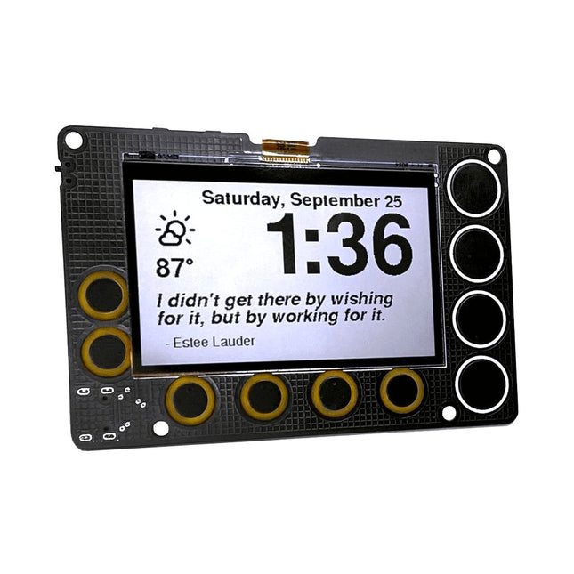
A low-power, open source, 2.7-inch IoT display powered by an ESP32-S2 module and featuring SHARP's Memory-in-Pixel (MiP) screen technology
The Newt is a battery-powered, always-on, wall-mountable display that can go online to retrieve weather, calendars, sports scores, to-do lists, quotes…really anything on the Internet! It is powered by an ESP32-S2 microcontroller that you can program with Arduino, CircuitPython, MicroPython, or ESP-IDF. It's perfect for makers:
Sharp’s Memory-in-Pixel (MiP) technology avoids the slow refresh times associated with E-Ink displays
A real-time clock (RTC) was added to support timers and alarms
The Newt was designed with battery operation in mind; every component on the board was chosen for its ability to operate at low power.
Newt was designed to operate 'untethered,' which means it can be mounted in places where a power cord would be inconvenient, for example a wall, refrigerator, mirror, or dry-erase board. With the optional stand, desks, shelves, and nightstands are also good options.
Newt is open source, and all design files and libraries are available for review, use, and modification. However, doing that is not required. Each Newt is delivered with working code with the following features:
Current weather details
Hourly and daily weather forecast
Alarm
Timer
Inspirational quotes
Air-quality forecast
Habit calendar
Pomodoro timer
Oblique Strategy cards
Only following the Wi-Fi provisioning instructions is needed to get started. No app downloads are required.
Specifications
Display
Sharp Memory LCD
Screen Size
2.7 inch
Resolution
240 x 400
Deep Sleep Current
30 uA
Refresh Rate
< 0.001 s
Periodic Screen Refresh Required
No
Input Buttons
10 capacitive pads, 1 push button
RTC included
Yes
Speaker included
Yes
Power Input
USB Type-C
Battery included
No
Programming Languages
Arduino, CircuitPython, ESP IDF, MicroPython
Dimensions
91 x 61 x 9 mm
Microcontroller
Espressif ESP32-S2-WROVER Module with 4 MB flash and 2 MB PSRAM
Wi-Fi capable
Supports Arduino, MicroPython, CircuitPython, and ESP-IDF
Deep sleep current as low as 25 μA
Display
2.7-inch, 240 x 400 pixel MiP LCD
Capable of delivering high-contrast, high-resolution, low-latency content with ultra-low power consumption
Reflective mode leverages ambient light to eliminate the need for a backlight
Time Keeping, Timers, and Alarms
Micro Crystal RV-3028-C7 RTC
Optimized for extreme low-power consumption (45 μA)
Able to simultaneously manage a periodic timer, a countdown timer, and an alarm
Hardware interrupt for timers and alarms
43 bytes of non-volatile user memory, 2 bytes of user RAM
Separate UNIX time counter
Buzzer
Speaker/buzzer with mini class-D amplifier on DAC output A0 can play tones or lo-fi audio clips
User Input
Power switch
Two programmable tactile buttons for Reset and Boot
10 capacitive touchpads
Power
Newt is designed to operate for one to two months between charges using a 500 mAH LiPo battery. The exact run time varies. (Heavy Wi-Fi use, in particular, will reduce battery charge more quickly.)
USB Type-C connector for programming, power, and charging
Low-quiescence voltage regulator (TOREX XC6220) that can output 1 A of current and operate as low as 8 μA.
JST connector for a Lithium-Ion battery
Battery-charging circuity (MCP73831)
Low-battery indicator (1 μA quiescence current)
Software
Newt hardware is compatible with open-source Arduino libraries for ESP32-S2, Adafruit GFX (fonts), Adafruit Sharp Memory Display (display writing), and RTC RV-3028-C7 (RTC)
Arduino libraries and sample programs are under development and will be available in our GitHub repository before launch
CircuitPython libraries and registration are on the roadmap, with the development of a CircuitPython library for the RV-3028 real-time clock as a key dependency
Included
Phambili Newt – Fully assembled with pre-loaded firmware
Laser-cut desktop stand
Mini-magnet feet
Required screws
Support & Documentation
Full instructions for use
GitHub: Arduino Library and Codebase
GitHub: Board schematics
Videos of prototypes or demos (build tracked on Hackaday)
At the core of this module is ESP32-S2, an Xtensa® 32-bit LX7 CPU that operates at up to 240 MHz. The chip has a low-power co-processor that can be used instead of the CPU to save power while performing tasks that do not require much computing power, such as monitoring of peripherals. ESP32-S2 integrates a rich set of peripherals, ranging from SPI, I²S, UART, I²C, LED PWM, TWAITM, LCD, Camera interface, ADC, DAC, touch sensor, temperature sensor, as well as up to 43 GPIOs. It also includes a full-speed USB On-The-Go (OTG) interface to enable USB communication.FeaturesMCU
ESP32-S2 embedded, Xtensa® single-core 32-bit LX7 microprocessor, up to 240 MHz
128 KB ROM
320 KB SRAM
16 KB SRAM in RTC
WiFi
802.11 b/g/n
Bit rate: 802.11n up to 150 Mbps
A-MPDU and A-MSDU aggregation
0.4 µs guard interval support
Center frequency range of operating channel: 2412 ~ 2484 MHz
Hardware
Interfaces: GPIO, SPI, LCD, UART, I²C, I²S, Camera interface, IR, pulse counter, LED PWM, TWAI (compatible with ISO 11898-1), USB OTG 1.1, ADC, DAC, touch sensor, temperature sensor
40 MHz crystal oscillator
4 MB SPI flash
Operating voltage/Power supply: 3.0 ~ 3.6 V
Operating temperature range: –40 ~ 85 °C
Dimensions: 18 × 31 × 3.3 mm
Applications
Generic Low-power IoT Sensor Hub
Generic Low-power IoT Data Loggers
Cameras for Video Streaming
Over-the-top (OTT) Devices
USB Devices
Speech Recognition
Image Recognition
Mesh Network
Home Automation
Smart Home Control Panel
Smart Building
Industrial Automation
Smart Agriculture
Audio Applications
Health Care Applications
Wi-Fi-enabled Toys
Wearable Electronics
Retail & Catering Applications
Smart POS Machines
The Milk-V Duo 256M is an ultra-compact embedded development platform based on the SG2002 chip. It can run Linux and RTOS, providing a reliable, low-cost, and high-performance platform for professionals, industrial ODMs, AIoT enthusiasts, DIY hobbyists, and creators.
This board is an upgraded version of Duo with a memory boost to 256M, catering to applications demanding larger memory capacities. The SG2002 elevates computational power to 1.0 TOPS @ INT8. It enables seamless switching between RISC-V/ARM architectures and supports simultaneous operation of dual systems. Additionally, it includes an array of rich GPIO interfaces such as SPI, UART, suitable for a wide range of hardware development in edge intelligent monitoring, including IP cameras, smart peephole locks, visual doorbells, and more.
SG2002 is a high-performance, low-power chip designed for various product fields such as edge intelligent surveillance IP cameras, smart door locks, visual doorbells, and home intelligence. It integrates H.264 video compression and decoding, H.265 video compression encoding, and ISP capabilities. It supports multiple image enhancement and correction algorithms such as HDR wide dynamic range, 3D noise reduction, defogging, and lens distortion correction, providing customers with professional-grade video image quality.
The chip also incorporates a self-developed TPU, delivering 1.0 TOPS of computing power under 8-bit integer operations. The specially designed TPU scheduling engine efficiently provides high-bandwidth data flow for all tensor processing unit cores. Additionally, it offers users a powerful deep learning model compiler and software SDK development kit. Leading deep learning frameworks like Caffe and Tensorflow can be easily ported to its platform. Furthermore, it includes security boot, secure updates, and encryption, providing a series of security solutions from development, mass production, to product applications.
The chip integrates an 8-bit MCU subsystem, replacing the typical external MCU to achieve cost-saving and power efficiency goals.
Specifications
SoC
SG2002
RISC-V CPU
C906 @ 1 Ghz + C906 @ 700 MHz
Arm CPU
1x Cortex-A53 @ 1 GHz
MCU
8051 @ 6 KB SRAM
Memory
256 MB SIP DRAM
TPU
1.0 TOPS @ INT8
Storage
1x microSD connector or 1x SD NAND on board
USB
1x USB-C for power and data, USB Pads available
CSI
1x 16P FPC connector (MIPI CSI 2-lane)
Sensor Support
5 M @ 30 fps
Ethernet
100 Mbps Ethernet with PHY
Audio
Via GPIO Pads
GPIO
Up to 26x GPIO Pads
Power
5 V/1 A
OS Support
Linux, RTOS
Dimensions
21 x 51 mm
Downloads
Documentation
GitHub
Specifications Operating Voltage: 3.3 V ESP-12E MCU Display Size: 1.28 inch USB Port for Power & Data Transmission Interface Pins: 4 GPIO, 1 GND, 1 Power Driver: GC9A01 Resolution240 x 240 Pixel Color: 65 K RGB Interface: SPI Downloads STEP File Dimensions 3D File Schematic GitHub
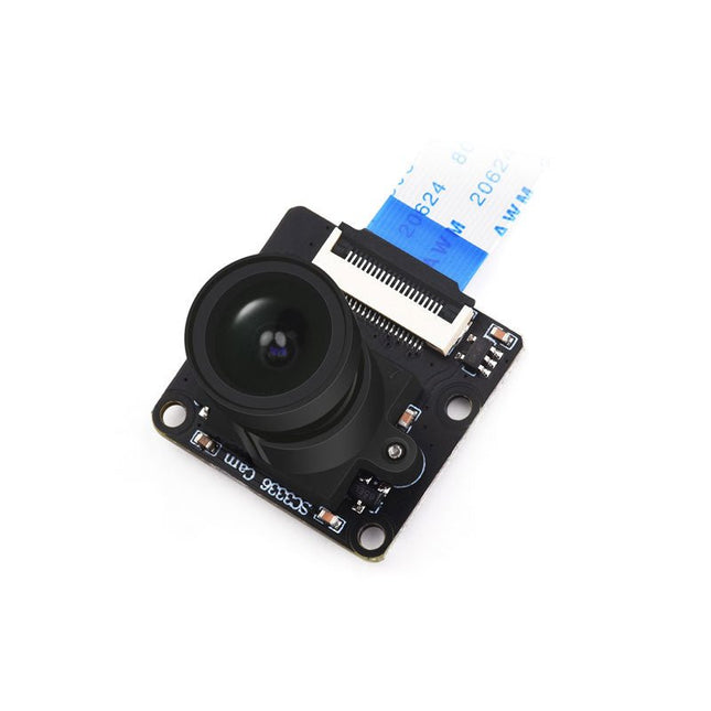
This camera module adopts a SmartSens SC3336 sensor chip with 3 MP resolution. It features high sensitivity, high SNR, and low light performance and it is capable of a more delicate and vivid night vision imaging effect, and can better adapt to ambient light changes. Also, it is compatible with Luckfox Pico series boards.
Specifications
Sensor
Sensor: SC3336
CMOS size: 1/2.8"
Pixels: 3 MP
Static resolution: 2304x1296
Maximum video frame rate: 30fps
Shutter: Rolling shutter
Lens
Focal length: 3.95 mm
Aperture: F2.0
FOV: 98.3° (diagonal)
Distortion: <33%
Focusing: Manual focus
Downloads
Wiki
The matte-black circuit board is extra thick and has subtle white markings, including an alphanumeric grid and PIN labels. The wiring pattern – that of classic breadboards – is easy to see by looking at the exposed traces on the bottom of the board.
The kit comes complete with the 'Integrated Circuit Leg' stand and 8 colour-coded thumbscrew terminal posts. Using the terminal posts and solder points, you can hook up to your 'IC' with bare wires, lugs, alligator clips, and/or solder joints. Connections to the 8 terminal posts are through the three-position strips on the PCB; each is labelled with the corresponding PIN.
Features
Anodized aluminium stand
8-32 size press-fit threaded inserts (8 pieces) pre-installed in the protoboard
All materials (including the circuit board and stand) are RoHS compliant (lead-free)
Tri lobular thread forming screws (6 pieces, black, 6-32 thread size) and spacers for mounting the stand.
Dimensions: 13.25 x 8.06 x 2.54 mm
Dimensions assembled: 13.25 x 9.9 x 4.3 cm
The FRDM-MCXN947 is a compact and versatile development board designed for rapid prototyping with MCX N94 and N54 microcontrollers. It features industry-standard headers for easy access to the MCU's I/Os, integrated open-standard serial interfaces, external flash memory, and an onboard MCU-Link debugger.
Specifications
Microcontroller
MCX-N947 Dual Arm Cortex-M33 cores @ 150 MHz each with optimized performance efficiency, up to 2 MB dual-bank flash with optional full ECC RAM, External flash
Accelerators: Neural Processing Unit, PowerQuad, Smart DMA, etc.
Memory Expansion
*DNP Micro SD card socket
Connectivity
Ethernet Phy and connector
HS USB-C connectors
SPI/I²C/UART connector (PMOD/mikroBUS, DNP)
WiFi connector (PMOD/mikroBUS, DNP)
CAN-FD transceiver
Debug
On-board MCU-Link debugger with CMSIS-DAP
JTAG/SWD connector
Sensor
P3T1755 I³C/I²C Temp Sensor, Touch Pad
Expansion Options
Arduino Header (with FRDM expansion rows)
FRDM Header
FlexIO/LCD Header
SmartDMA/Camera Header
Pmod *DNP
mikroBUS
User Interface
RGB user LED, plus Reset, ISP, Wakeup buttons
Included
1x FRDM-MCXN947 Development Board
1x USB-C Cable
1x Quick Start Guide
Downloads
Datasheet
Block diagram
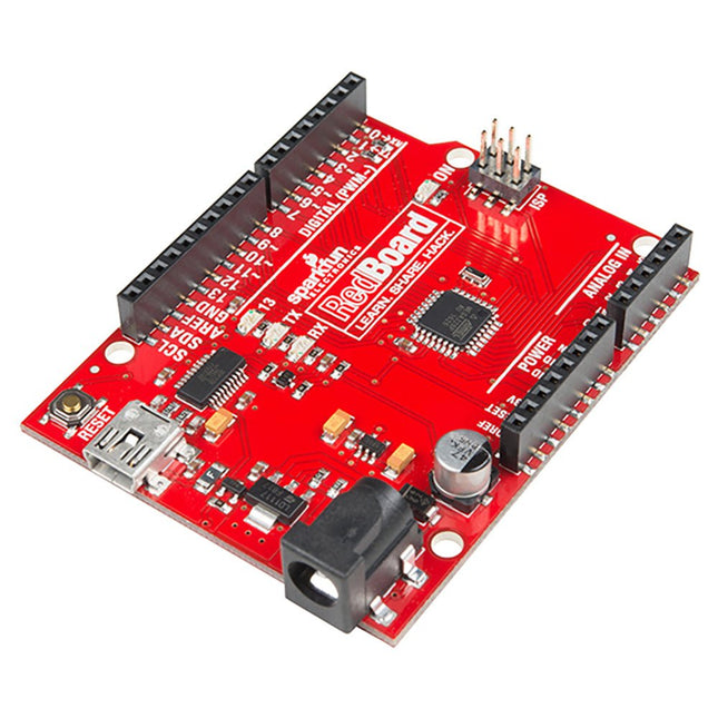
Are you tired of all the different Arduino boards, and having to choose which features you need? Wouldn't it be much simpler to have all the best features on the same board and not have to compromise? That is precisely what the people at SparkFun thought and delivered the fantastic SparkFun RedBoard Programmed with Arduino. Features ATmega328 microcontroller with Optiboot (UNO) Bootloader Input voltage: 7-15 V 0-5 V outputs with 3.3 V compatible inputs 6 Analog Inputs 14 Digital I/O Pins (6 PWM outputs) ISP Header 16 MHz Clock Spee 32 k Flash Memory R3 Shield Compatible All SMD Construction USB Programming Facilitated by the Ubiquitous FTDI FT231X Red PCB The SparkFun RedBoard combines the stability of the FTDI, the simplicity of the Uno's Optiboot bootloader, and the R3 shield compatibility of the Uno R3. RedBoard has the hardware peripherals you are used to: 6 Analog Inputs 14 Digital I/O pins (6 PWM pins) SPI UART External interrupts Downloads Drivers GitHub
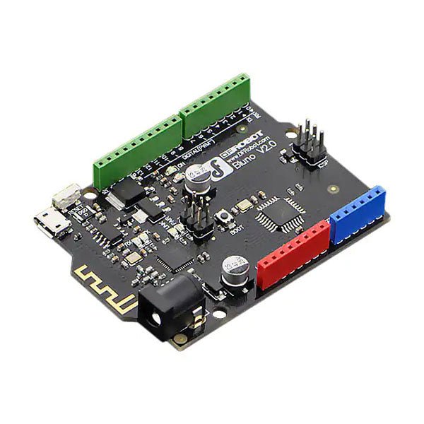
Bluno is the first of its kind in integrating Bluetooth 4.0 (BLE) module into Arduino Uno, making it an ideal prototyping platform for both software and hardware developers to go BLE. You will be able to develop your own smart bracelet, smart pedometer, and more. Through the low-power Bluetooth 4.0 technology, real-time low energy communication can be made really easy.
Bluno integrates a TI CC2540 BT 4.0 chip with the Arduino UNno. It allows wireless programming via BLE, supports Bluetooth HID, AT command to config BLE and you can upgrade BLE firmware easily. Bluno is also compatible with all 'Arduino Uno' pins which means any project made with Uno can directly go wireless!
Specifications
On-board BLE chip: TI CC2540
Wireless Programming via BLE
Support Bluetooth HID
Support AT command to config the BLE
Transparent communication through Serial
Upgrade BLE firmware easily
DC Supply: USB Powered or External 7~12 V DC
Microcontroller: Atmega328
Bootloader: Arduino Uno ( disconnect any BLE device before uploading a new sketch )
Compatible with the Arduino Uno pin mapping
Size: 60 x 53 mm(2.36 x 2.08')
Weight: 30 g
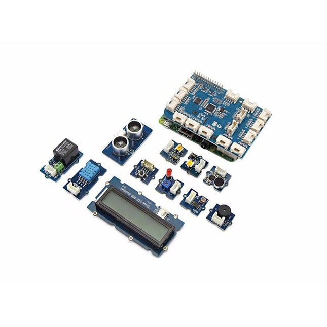
GrovePi+ is stacked on top of the Raspberry Pi without the need for any other connections. Communication between the two occurs over the I²C interface. All Grove modules connect to the universal Grove connectors on the GrovePi+ shield via the universal 4-pin connector cable.
Grove modules work on analog and digital signals and can be connected directly to the ATMEGA328 microcontroller on the Grove Pi+. The microcontroller acts as an interpreter between the Raspberry Pi and the Grove sensors. It sends, receives, and executes commands sent by the Raspberry Pi.
Features
One GrovePi+ board together with 12 popular Grove sensors and 10 Grove cables
GrovePi+ is compatible with Raspberry Pi A+, B, B+ / 2, 3, 4.
CE certified and compatible with Linux and Win 10 IoT.
Included
1x Grove Pi+
1x Grove - Rotary Angle Sensor
1x Grove - Sound Sensor
1x Grove - LCD RGB Backlight
1x Grove - Temp&Humi Sensor
1x Grove - Red LED
1x Grove - Light Sensor
1x Grove - Buzzer
1x Grove - Relay
1x Grove - Blue LED
1x Grove - Button
1x GrovePi+ Guidebook
10x Cables
1x Grove - UItrasonic Ranger
1x Grove - Green LED
The LuckFox Pico Ultra is a compact single-board computer (SBC) powered by the Rockchip RV1106G3 chipset, designed for AI processing, multimedia, and low-power embedded applications.
It comes equipped with a built-in 1 TOPS NPU, making it ideal for edge AI workloads. With 256 MB RAM, 8 GB onboard eMMC storage, integrated WiFi, and support for the LuckFox PoE module, the board delivers both performance and versatility across a wide range of use cases.
Running Linux, the LuckFox Pico Ultra supports a variety of interfaces – including MIPI CSI, RGB LCD, GPIO, UART, SPI, I²C, and USB – providing a simple and efficient development platform for applications in smart home, industrial control, and IoT.
Specifications
Chip
Rockchip RV1106G3
Processor
Cortex-A7 1.2 GHz
Neural Network Processor (NPU)
1 TOPS, supports int4, int8, int16
Image Processor (ISP)
Max input 5M @30fps
Memory
256 MB DDR3L
WiFi + Bluetooth
2.4GHz WiFi-6 Bluetooth 5.2/BLE
Camera Interface
MIPI CSI 2-lane
DPI Interface
RGB666
PoE Interface
IEEE 802.3af PoE
Speaker interface
MX1.25 mm
USB
USB 2.0 Host/Device
GPIO
30 GPIO pins
Ethernet
10/100M Ethernet controller and embedded PHY
Default Storage Medium
eMMC (8 GB)
Included
1x LuckFox Pico Ultra W
1x LuckFox PoE module
1x IPX 2.4G 2 db antenna
1x USB-A to USB-C cable
1x Screws pack
Downloads
Wiki
Grove Piezo Vibration Sensor is suitable for measurements of flexibility, vibration, impact and touch. The module is based on PZT film sensor LDT0-028. When the sensor moves back and forth, a certain voltage will be created by the voltage comparator inside of it.
Therefore, outputs high & low levels. In spite of the fact that it has a high receptivity for strong impacts, a wide dynamic range (0.001 Hz~1000 MHz) also guarantees excellent measuring performance. Finally, you can adjust its sensitivity by adjusting the potentiometer with a screw.
Features
Standard grove socket
Wide dynamic range:0.001 Hz~1000 MHz
Adjustable sensitivity
High receptivity for strong impact
Applications
Vibration Sensing in Washing Machine
Low Power Wake-up Switch
Low-Cost Vibration Sensing
Car Alarms
Body Movement
Security Systems
Downloads
Download Wiki PDF
Grove - Piezo Vibration Sensor Eagle File
Grove - Piezo Vibration Sensor Schematic PDF File
Grove - Piezo Vibration Sensor PCB PDF File
Piezo Vibration Sensor Datasheet
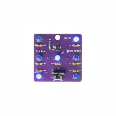
If you are looking for an easy way to get started with soldering or simply want to make a small portable gadget, this set is a great opportunity. "LED cube" is an educational set for learning the soldering skill, with which you get a small electronic game at the end. After you turn on and shake this board, certain leds will light up randomly and symbolize the number, as if a real die had been thrown.
It is based on the Attiny404 microcontroller, programmed in Arduino, and there is a battery on the back which makes this gadget portable. There is also a keychain so you can always carry your new game with you! Soldering is easy according to the markings on the board.
Included
1x PCB
1x ATtiny404 microcontroller
7x LEDs
7x Resistors (330 ohm)
1x Resistor (10 kohm)
1x Battery holder
1x CR2032 battery
1x Switch
1x Vibration sensor SW-18020P
1x Keychain ring
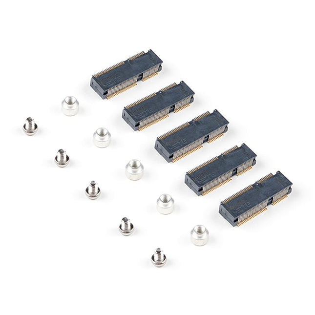
The MicroMod DIY Carrier Kit includes five M.2 connectors (4.2mm height), screws, and standoffs so that you can get all the special parts you may need to make your own carrier board.
MicroMod uses the standard M.2 connector. This is the same connector found on modern motherboards and laptops. There are various locations for the plastic ‘key’ on the M.2 connector to prevent a user from inserting an incompatible device. The MicroMod standard uses the ‘E’ key and further modifies the M.2 standard by moving the mounting screw 4mm to the side. The ‘E’ key is fairly common so a user could insert an M.2 compatible Wifi module. Still, because the screw mount doesn’t align, the user would not secure an incompatible device into a MicroMod carrier board.
Features
5x Machine Screws
Phillips Head #0 (but #00 to #1 works)
Thread: M2.5
Length: 3 mm
5x SMD Reflow Compatible Standoffs
Thread: M2.5 x 0.4
Height: 2.5 mm
5x M.2 MicroMod Connectors
Key: E
Height: 4.2 mm
Pin count: 67
Pitch: 0.5 mm
The SparkFun RP2040 mikroBUS Development Board is a low-cost, high performance platform with flexible digital interfaces featuring the Raspberry Pi Foundation's RP2040 microcontroller. Besides the Thing Plus or Feather PTH pin layout, the board also includes a microSD card slot, 16 MB (128 Mbit) flash memory, a JST single cell battery connector (with a charging circuit and fuel gauge sensor), an addressable WS2812 RGB LED, JTAG PTH pins, four (4-40 screw) mounting holes, our signature Qwiic connectors, and a mikroBUS socket. The mikroBUS standard was developed by MikroElektronika. Similar to Qwiic and MicroMod interfaces, the mikroBUS socket provides a standardized connection for add-on Click boards to be attached to a development board and is comprised of a pair of 8-pin female headers with a standardized pin configuration. The pins consist of three groups of communications pins (SPI, UART and I²C), six additional pins (PWM, Interrupt, Analog input, Reset and Chip select), and two power groups (3.3 V and 5 V). The RP2040 is supported with both C/C++ and MicroPython cross-platform development environments, including easy access to runtime debugging. It has UF2 boot and floating-point routines baked into the chip. While the chip has a large amount of internal RAM, the board includes an additional 16 MB of external QSPI flash memory to store program code. The RP2040 contains two ARM Cortex-M0+ processors (up to 133 MHz) and features: 264 kB of embedded SRAM in six banks 6 dedicated IO for SPI Flash (supporting XIP) 30 multifunction GPIO: Dedicated hardware for commonly used peripherals Programmable IO for extended peripheral support Four 12-bit ADC channels with internal temperature sensor (up to 0.5 MSa/s) USB 1.1 Host/Device functionality Features (SparkFun RP2040 mikroBUS Dev. Board) Raspberry Pi Foundation's RP2040 microcontroller 18 Multifunctional GPIO Pins Four available 12-bit ADC channels with internal temperature sensor (500kSa/s) Up to eight 2-channel PWM Up to two UARTs Up to two I²C buses Up to two SPI buses Thing Plus (or Feather) Pin Layout: 28 PTH Pins USB-C Connector: USB 1.1 Host/Device functionality 2-pin JST Connector for a LiPo Battery (not included): 500mA charging circuit 4-pin JST Qwiic Connector LEDs:
PWR - Red 3.3V power indicator
CHG - Yellow battery charging indicator
25 - Blue status/test LED (GPIO 25)
WS2812 - Addressable RGB LED (GPIO 08) Buttons: Boot Reset JTAG PTH Pins 16MB QSPI Flash Memory µSD Card Slot mikroBUS Socket Dimensions: 3.7' x 1.2' Four Mounting Holes: 4-40 screw compatible Downloads Schematic Eagle Files Board Dimensions Hookup Guide Qwiic Info Page GitHub Hardware Repository