The RP2040 contains two ARM Cortex-M0+ processors (up to 133 MHz) and features:
264 kB of embedded SRAM in six banks
6 dedicated IO for SPI Flash (supporting XIP)
30 multifunction GPIO:
Dedicated hardware for commonly used peripherals
Programmable IO for extended peripheral support
Four 12-bit ADC channels with internal temperature sensor (up to 0.5 MSa/s)
USB 1.1 Host/Device functionality
The RP2040 is supported with C/C++ and MicroPython cross-platform development environments, including easy access to runtime debugging. It has a UF2 boot and floating-point routines baked into the chip. While the chip has a large internal RAM, the board includes an additional 16 MB of external QSPI flash memory to store program code.
Features
Raspberry Pi Foundation's RP2040 microcontroller
16MB QSPI Flash Memory
JTAG PTH Pins
Thing Plus (or Feather) Form-Factor:
18x Multifunctional GPIO Pins
Four available 12-bit ADC channels with an internal temperature sensor (500 kSa/s)
Up to eight 2-channel PWM
Up to two UARTs
Up to two I²C buses
Up to two SPI buses
USB-C Connector:
USB 1.1 Host/Device functionality
2-pin JST Connector for a LiPo Battery (not included):
500 mA charging circuit
Qwiic Connector
Buttons:
Boot
Reset
LEDs:
PWR - Red 3.3 V power indicator
CHG - Yellow battery charging indicator
25 - Blue status/test LED (GPIO 25)
WS2812 - Addressable RGB LED (GPIO 08)
Four Mounting Holes:
4-40 screw compatible
Dimensions: 2.3' x 0.9'
RP2040 Features
Dual Cortex M0+ processors, up to 133 MHz
264 kB of embedded SRAM in 6 banks
6 dedicated IO for QSPI flash, supporting execute in place (XIP)
30 programmable IO for extended peripheral support
SWD interface
Timer with 4 alarms
Real-time counter (RTC)
USB 1.1 Host/Device functionality
Supported programming languages
MicroPython
C/C++
The RedBoard Artemis has the improved power conditioning and USB to serial that we've refined over the years on our RedBoard line of products. A modern USB-C connector makes programming easy. A Qwiic connector makes I²C easy. The RedBoard Artemis is fully compatible with SparkFun's Arduino core and can be programmed easily under the Arduino IDE. We've exposed the JTAG connector for more advanced users who prefer to use professional tools' power and speed. We've added a digital MEMS microphone for folks wanting to experiment with always-on voice commands with TensorFlow and machine learning. We've even added a convenient jumper to measure current consumption for low power testing.
With 1MB flash and 384k RAM, you'll have plenty of room for your sketches. The on-board Artemis module runs at 48MHz with a 96MHz turbo mode available and with Bluetooth to boot!
Features
Arduino Uno R3 Footprint
1M Flash / 384k RAM
48MHz / 96MHz turbo available
24 GPIO - all interrupt capable
21 PWM channels
Built-in BLE radio
10 ADC channels with 14-bit precision
2 UARTs
6 I²C buses
4 SPI buses
PDM Interface
I²S Interface
Qwiic Connector
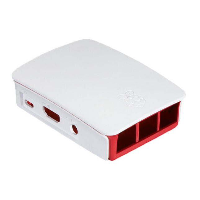
High-quality ABS construction Removable side panels and lid for easy access to GPIO, camera and display connectors Light pipes for power and activity LEDs Extraordinarily handsome Colour: white/red
The RP2040 utilizes dual ARM Cortex-M0+ processors (up to 133MHz):
264kB of embedded SRAM in six banks
6 dedicated IO for SPI Flash (supporting XIP)
30 multifunction GPIO:
Dedicated hardware for commonly used peripherals
Programmable IO for extended peripheral support
Four 12-bit ADC channels with internal temperature sensor (up to 0.5 MSa/s)
USB 1.1 Host/Device functionality
The RP2040 is supported with C/C++ and MicroPython cross-platform development environments, including easy access to runtime debugging. It has a UF2 boot and floating-point routines baked into the chip. The built-in USB can act as both device and host. It has two symmetric cores and high internal bandwidth, making it useful for signal processing and video. While the chip has a large internal RAM, the board includes an additional external flash chip.
Features
Dual Cortex M0+ processors, up to 133 MHz
264 kB of embedded SRAM in 6 banks
6 dedicated IO for QSPI flash, supporting execute in place (XIP)
30 programmable IO for extended peripheral support
SWD interface
Timer with 4 alarms
Real-time counter (RTC)
USB 1.1 Host/Device functionality
Supported programming languages
MicroPython
C/C++
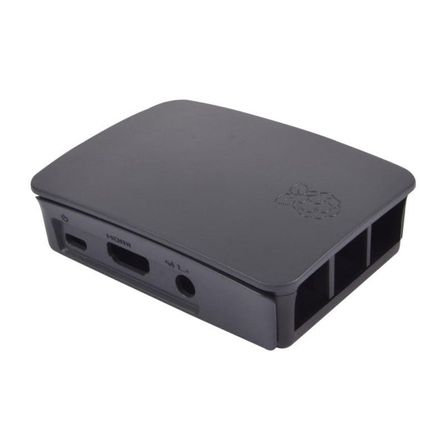
High-quality ABS construction Removable side panels and lid for easy access to GPIO, camera and display connectors Light pipes for power and activity LEDs Extraordinarily handsome Colour: black/grey
Features Build in USB to Serial interface Build-in PCB antenna Powered by Pineseed BL602 SoC using Pinenut model: 12S stamp 2 MB Flash USB-C connection Suitable to breadboard BIY project On board three color LEDs output Dimensions: 25.4 x 44.0 mm Note: USB cable is not included.
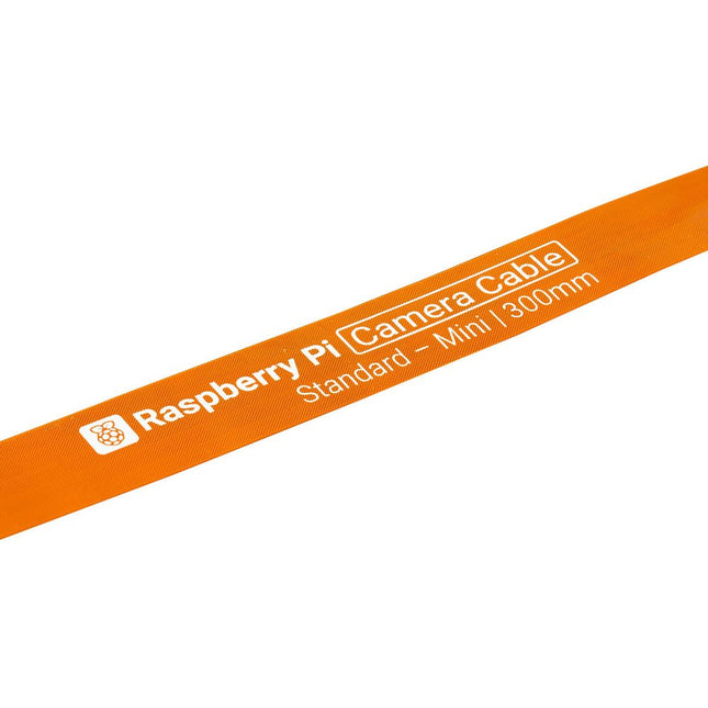
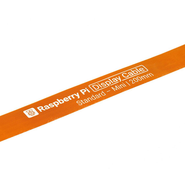
Raspberry Pi 5 provides two four-lane MIPI connectors, each of which can support either a camera or a display. These connectors use the same 22-way, 0.5 mm-pitch “mini” FPC format as the Compute Module Development Kit, and require adapter cables to connect to the 15-way, 1 mm-pitch “standard” format connectors on current Raspbery Pi camera and display products.These mini-to-standard adapter cables for cameras and displays (note that a camera cable should not be used with a display, and vice versa) are available in 200 mm, 300 mm and 500 mm lengths.
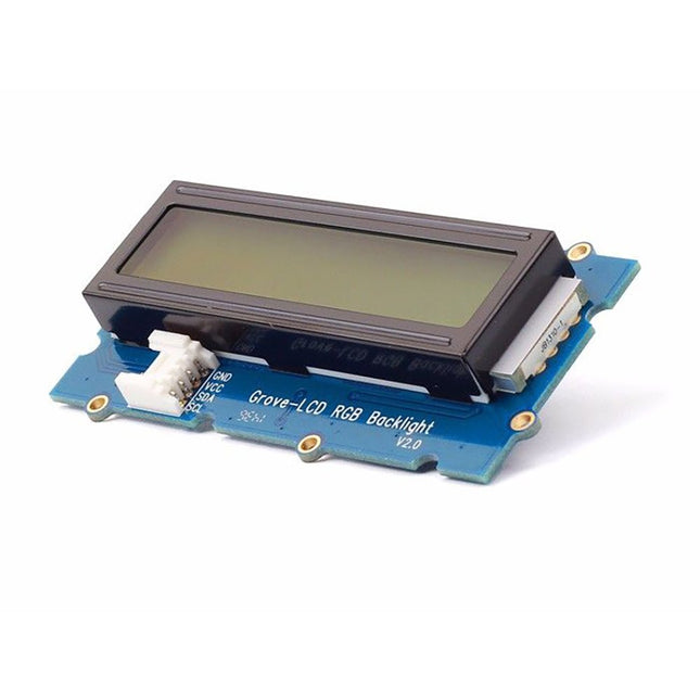
With the help of the Grove I²C connector, only 2 signal pins and 2 power pins are needed. You don't even need to care about how to connect these pins. Just plug it into the I²C interface on Seeeduino or Arduino/Raspberry Pi+baseshield via the Grove cable.
No complicated wiring, no soldering, no need to worry about burning the LCD caused by the wrong current limiting resistor. Easy peasy.
Specifications
Battery: Exclude
Input Voltage: 5 V
Dimensions: 83 x 44 x 13 mm
Weight: 42 g
The Arduino Nano 33 BLE Rev2 stands at the forefront of innovation, leveraging the advanced capabilities of the nRF52840 microcontroller. This 32-bit Arm Cortex-M4 CPU, operating at an impressive 64 MHz, empowers developers for a wide range of projects. The added compatibility with MicroPython enhances the board's flexibility, making it accessible to a broader community of developers.
The standout feature of this development board is its Bluetooth Low Energy (Bluetooth LE) capability, enabling effortless communication with other Bluetooth LE-enabled devices. This opens up a realm of possibilities for creators, allowing them to seamlessly share data and integrate their projects with a wide array of connected technologies.
Designed with versatility in mind, the Nano 33 BLE Rev2 is equipped with a built-in 9-axis Inertial Measurement Unit (IMU). This IMU is a game-changer, offering precise measurements of position, direction, and acceleration. Whether you're developing wearables or devices that demand real-time motion tracking, the onboard IMU ensures unparalleled accuracy and reliability.
In essence, the Nano 33 BLE Rev2 strikes the perfect balance between size and features, making it the ultimate choice for crafting wearable devices seamlessly connected to your smartphone. Whether you're a seasoned developer or a hobbyist embarking on a new adventure in connected technology, this development board opens up a world of possibilities for innovation and creativity. Elevate your projects with the power and flexibility of the Nano 33 BLE Rev2.
Specifications
Microcontroller
nRF52840
USB connector
Micro USB
Pins
Built-in LED Pins
13
Digital I/O Pins
14
Analog Input Pins
8
PWM Pins
All digital pins (4 at once)
External interrupts
All digital pins
Connectivity
Bluetooth
u-blox NINA-B306
Sensors
IMU
BMI270 (3-axis accelerometer + 3-axis gyroscope) + BMM150 (3-axis Magnetometer)
Communication
UART
RX/TX
I²C
A4 (SDA), A5 (SCL)
SPI
D11 (COPI), D12 (CIPO), D13 (SCK). Use any GPIO for Chip Select (CS)
Power
I/O Voltage
3.3 V
Input Voltage (nominal)
5-18 V
DC Current per I/O Pin
10 mA
Clock Speed
Processor
nRF52840 64 MHz
Memory
nRF52840
256 KB SRAM, 1 MB flash
Dimensions
18 x 45 mm
Downloads
Datasheet
Schematics
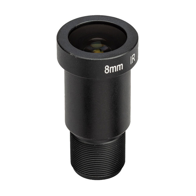
The M12 Mount Lens (12 MP, 8 mm) is ideal for use with the Raspberry Pi HQ Camera Module, offering sharp and detailed imaging for a wide range of applications.
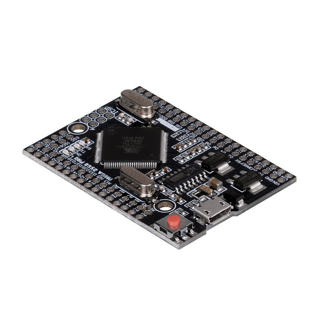
This JOY-iT microcontroller board opens the world of programming to you and offers you the same computing power as the Mega 2560, but with a smaller foot-print. It also has many more connectors than comparable boards (Arduino Uno). It is powered by the Arduino IDE and power can be supplied either via the USB port or the VIN pins. This allows you to use it safely with many other devices, e.g. desktop PC. Therefore the Mega 2560 Pro is highly integrable.
Features
Microcontroller
ATmega2560 - 16AU
Storage
Flash 256 KB, SRAM 8 KB, EEPRom 4 KB
Amount of Pins:Digital I/OPWM OutputAnalog Input
541516
Compatible with
Arduino, Desktop PCs, etc.
Special features
USB Port or Power Pins for power supply
Interface converter
Micro USB to USB UART
Size
55 x 38 mm
Items delivered
JOY-iT Mega 2560 Pro with Pins
Further Specifications
Input Voltage
7 - 9 Volt on Vin, 5 Volt on mUSB
Logic level
5 Volt
Output current
800 mA
Voltage regulator
LDO (for up to 12 V peak)
Frequency
16 MHz (12 MHz are possible for data exchange)
Downloads
Manual
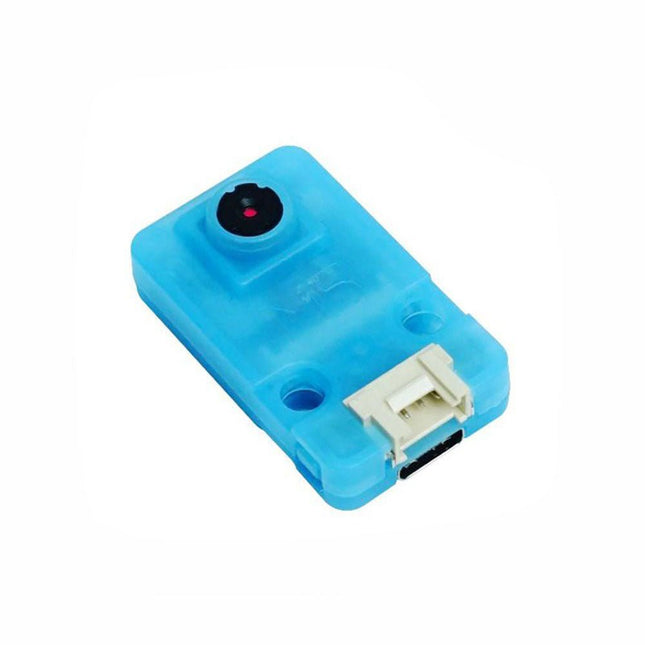
OV7740 is a AI Camera powered by Kendryte K210, an edge computing system-on-chip(SoC) with a dual-core 64bit RISC-V CPU and state-of-art neural network processor.
Features
Dual-Core 64-bit RISC-V RV64IMAFDC (RV64GC) CPU / 400Mhz(Normal)
Dual Independent Double Precision FPU
8MiB 64bit width On-Chip SRAM
Neural Network Processor(KPU) / 0.8Tops
Field-Programmable IO Array (FPIOA)
AES, SHA256 Accelerator
Direct Memory Access Controller (DMAC)
Micropython Support
Firmware encryption support
On-board Hardware:
Flash: 16M Camera :OV7740
2x Buttons
Status Indicator LED
External storage: TF card/Micro SD
Interface: HY2.0/compatible GROVE
Applications
Face recognition/detection
Object detection/classification
Obtain the size and coordinates of the target in real-time
Obtain the type of detected target in real-time
Shape recognition Video recorder
Included
1x UNIT-V(include 20cm 4P cable and USB-C cable)
The Mr. Pulsar Violent Turbo Fan X3 Pro delivers powerful airflow with its impressive 140,000 RPM motor, offering exceptional performance in a compact, portable design.
Featuring an 8,000 mAh battery for extended wireless operation, adjustable airflow speeds, and weighing just 277 grams, it's perfect for quick tasks like computer cleaning, drying pets, inflating air mattresses, removing dust, or even blowing snow from your car.
Specifications
Motor speed
140,000 RPM
Battery
8,000 mAh Lithium battery
Dimensions
160 x 60 x 90 mm
Weight
277 g
Included
1x Mr. Pulsar Violent Turbo Fan X3 Pro
1x Short nozzle
1x Storage bag
1x USB-C cable
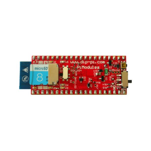
The DiP-Pi PIoT is an Advanced Powered, WiFi connectivity System with sensors embedded interfaces that cover most of possible needs for IoT application based on Raspberry Pi Pico. It can supply the system with up to 1.5 A @ 4.8 V delivered from 6-18 VDC on various powering schemes like Cars, Industrial plant etc., additionally to original micro-USB of the Raspberry Pi Pico. It supports LiPo or Li-Ion Battery with Automatic Charger as also automatic switching from cable powering to battery powering or reverse (UPS functionality) when cable powering lost. Extended Powering Source (EPR) is protected with PPTC Resettable fuse, Reverse Polarity, as also ESD.
The DiP-Pi PIoT contains Raspberry Pi Pico embedded RESET button as also ON/OFF Slide Switch that is acting on all powering sources (USB, EPR or Battery). User can monitor (via Raspberry Pi Pico A/D pins) battery level and EPR Level with PICO’s A/D converters. Both A/D inputs are bridged with 0402 resistors (0 OHM) therefore if for any reason user needs to use those Pico pins for their own application can be easy removed. The charger is automatically charging connected battery (if used) but in addition user can switch charger ON/OFF if their application needs it.
DiP-Pi PIoT can be used for cable powered IoT systems, but also for pure Battery Powered System with ON/OFF. Each powering source status is indicated by separate informative LEDs (VBUS, VSYS, VEPR, CHGR, V3V3).
User can use any capacity of LiPo or Li-Ion type; however, must take care to use PCB protected batteries with max discharge current allowed of 2 A. The embedded battery charger is set to charge battery with 240 mA current. This current is set by resistor so if user need more/less can himself to change it. The DiP-Pi PIoT is also equipped with WiFi ESP8266 Clone module with embedded antenna. This feature open a wide range of IoT applications based on it.
In Addition to all above features DiP-Pi PIoT is equipped with embedded 1-wire, DHT11/22 sensors, and micro–SD Card interfaces. Combination of the extended powering, battery, and sensors interfaces make the DiP-Pi PIoT ideal for IoT applications like data logger, plants monitoring, refrigerators monitoring etc.
DiP-Pi PIoT is supported with plenty of ready to use examples written in Micro Python or C/C++.
Specifications
General
Dimensions 21 x 51 mm
Raspberry Pi Pico pinout compatible
Independent Informative LEDs (VBUS, VSYS, VEPR, CHGR, V3V3)
Raspberry Pi Pico RESET Button
ON/OFF Slide Switch acting on all powering sources (USB, EPR, Battery)
External Powering 6-18 VDC (Cars, Industrial Applications etc.)
External Power (6-18 VDC) Level Monitoring
Battery Level Monitoring
Inverse Polarity Protection
PPTC Fuse Protection
ESD Protection
Automatic Battery Charger (for PCB protected LiPo, Li-Ion – 2 A Max) Automatic/User Control
Automatic Switch from Cable Powering to Battery Powering and reverse (UPS Functionality)
Various powering schemes can be used at the same time with USB Powering, External Powering and Battery Powering
1.5 A @ 4.8 V Buck Converter on EPR
Embedded 3.3 V @ 600 mA LDO
ESP8266 Clone WiFi Connectivity
ESP8266 Firmware Upload Switch
Embedded 1-wire Interface
Embedded DHT-11/22 Interface
Powering Options
Raspberry Pi Pico micro-USB (via VBUS)
External Powering 6-18 V (via dedicated Socket – 3.4/1.3 mm)
External Battery
Supported Battery Types
LiPo with protection PCB max current 2A
Li-Ion with protection PCB max current 2A
Embedded Peripherals and Interfaces
Embedded 1-wire interface
Embedded DHT-11/22 Interface
Micro SD Card Socket
Programmer Interface
Standard Raspberry Pi Pico C/C++
Standard Raspberry Pi Pico Micro Python
Case Compatibility
DiP-Pi Plexi-Cut Case
System Monitoring
Battery Level via Raspberry Pi Pico ADC0 (GP26)
EPR Level via Raspberry Pi Pico ADC1 (GP27)
Informative LEDs
VB (VUSB)
VS (VSYS)
VE (VEPR)
CH (VCHR)
V3 (V3V3)
System Protection
Direct Raspberry Pi Pico Hardware Reset Button
ESD Protection on EPR
Reverse Polarity Protection on EPR
PPTC 500 mA @ 18 V fuse on EPR
EPR/LDO Over Temperature protection
EPR/LDO Over Current protection
System Design
Designed and Simulated with PDA Analyzer with one of the most advanced CAD/CAM Tools – Altium Designer
Industrial Originated
PCB Construction
2 ozcopper PCB manufactured for proper high current supply and cooling
6 mils track/6 mils gap technology 2 layers PCB
PCB Surface Finishing – Immersion Gold
Multi-layer Copper Thermal Pipes for increased System Thermal Response and better passive cooling
Downloads
Datasheet
Manual
This PCIe to M.2 adapter is specifically designed for the Raspberry Pi 5. It supports the NVMe protocol for M.2 SSDs, enabling fast read and write operations, and adheres to the HAT+ standard. The adapter is compatible with M.2 SSDs in the 2230 and 2242 sizes.
Included
1x PCIe to M.2 HAT+ Adapter
1x 2x20 Pin header
1x 16P cable (40 mm)
1x Standoff pack
Downloads
Wiki
Raspberry Pi 5 provides two four-lane MIPI connectors, each of which can support either a camera or a display. These connectors use the same 22-way, 0.5 mm-pitch “mini” FPC format as the Compute Module Development Kit, and require adapter cables to connect to the 15-way, 1 mm-pitch “standard” format connectors on current Raspbery Pi camera and display products.These mini-to-standard adapter cables for cameras and displays (note that a camera cable should not be used with a display, and vice versa) are available in 200 mm, 300 mm and 500 mm lengths.
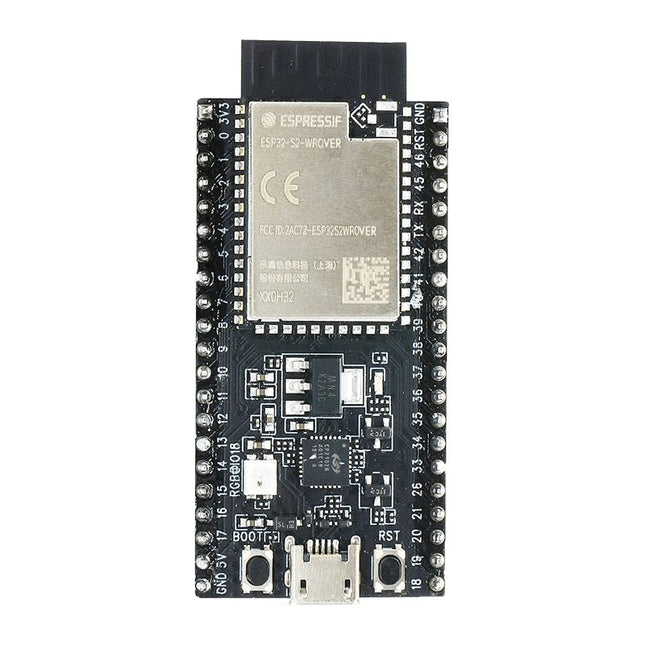
ESP32-S2-Saola-1R is a small-sized ESP32-S2 based development board. Most of the I/O pins are broken out to the pin headers on both sides for easy interfacing. Developers can either connect peripherals with jumper wires or mount ESP32-S2-Saola-1R on a breadboard.ESP32-S2-Saola-1R is equipped with the ESP32-S2-WROVER module, a powerful, generic Wi-Fi MCU module that has a rich set of peripherals. It is an ideal choice for a wide variety of application scenarios relating to Internet of Things (IoT), wearable electronics and smart home. The board a PCB antenna and features a 4 MB external SPI flash and an additional 2 MB SPI Pseudo static RAM (PSRAM).FeaturesMCU
ESP32-S2 embedded, Xtensa® single-core 32-bit LX7 microprocessor, up to 240 MHz
128 KB ROM
320 KB SRAM
16 KB SRAM in RTC
WiFi
802.11 b/g/n
Bit rate: 802.11n up to 150 Mbps
A-MPDU and A-MSDU aggregation
0.4 µs guard interval support
Center frequency range of operating channel: 2412 ~ 2484 MHz
Hardware
Interfaces: GPIO, SPI, LCD, UART, I²C, I²S, Camera interface, IR, pulse counter, LED PWM, TWAI (compatible with ISO 11898-1), USB OTG 1.1, ADC, DAC, touch sensor, temperature sensor
40 MHz crystal oscillator
4 MB SPI flash
Operating voltage/Power supply: 3.0 ~ 3.6 V
Operating temperature range: –40 ~ 85 °C
Dimensions: 18 × 31 × 3.3 mm
Applications
Generic Low-power IoT Sensor Hub
Generic Low-power IoT Data Loggers
Cameras for Video Streaming
Over-the-top (OTT) Devices
USB Devices
Speech Recognition
Image Recognition
Mesh Network
Home Automation
Smart Home Control Panel
Smart Building
Industrial Automation
Smart Agriculture
Audio Applications
Health Care Applications
Wi-Fi-enabled Toys
Wearable Electronics
Retail & Catering Applications
Smart POS Machines
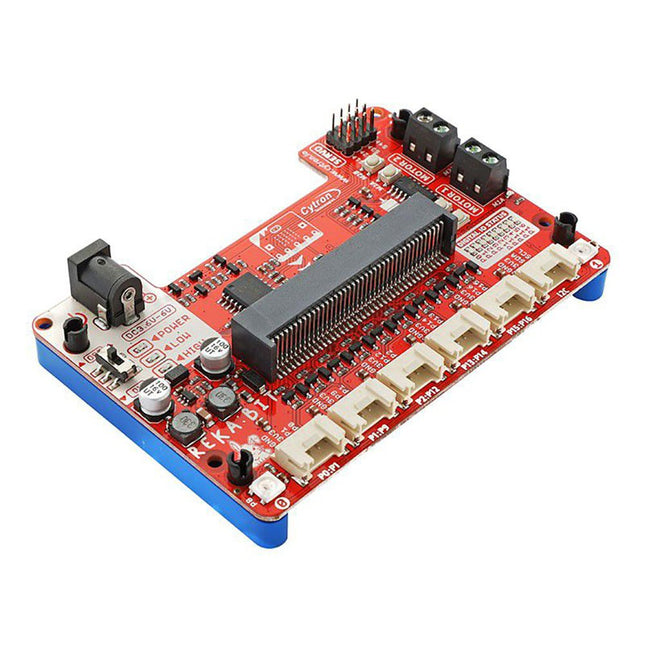
Program your REKA:BIT with Microsoft MakeCode Editor. Just add REKA:BIT MakeCode Extension and you’re good to go. If you’re a beginner, you can start with the block programming mode; simply drag, drop and snap the coding blocks together. For more advanced users, you can easily switch into JavaScript or Python mode on MakeCode Editor for text-based programming.
REKA:BIT possesses a lot of indicator LEDs to assist your coding and troubleshooting. It covers the IO pins connected to all six Grove ports and DC motor outputs from the co-processor. One is able to check his/her program and circuit connection easily by monitoring these LEDs.
Besides, REKA:BIT also has a power on/off indicator, undervoltage, and overvoltage LEDs built-in to give appropriate warnings should there be any problem with the power input.
REKA:BIT features a co-processor to handle multitasking more efficiently. Playing music while controlling up to 4x servo motors and 2x DC motors, animating micro:bit LED matrix, and even lighting up RGB LEDs in different colors, all at the same time, is not a problem for REKA:BIT.
Features
2x DC motor terminals
Built-in motor quick test buttons (no coding needed)
4x Servo motor ports
2x Neopixel RGB LEDs
6x Grove port (3.3 V)
3x Analog Input / Digital IO ports
2x Digital IO ports
1x I²C Interface
DC jack for power input (3.6-6 V DC)
ON/OFF switch
Power on indicator
Undervoltage (LOW) indicator & protection
Over-voltage (HIGH) indicator & protection
Dimensions: 10.4 x 72 x 15 mm
Included
1x REKA:BIT expansion board
1x USB power and data cable
1x 4xAA battery holder
1x Mini screwdriver
3x Grove to female header cable
2x Building block 1x9 lift arm
4x Building block friction pin
Please note: micro:bit board not included
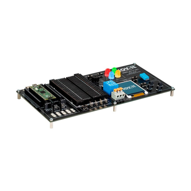
The Explorer Board is the easy and efficient way to develop your Raspberry Pi Pico projects.
Since the most important components are already integrated, you save time and effort on wiring. The Explorer Board has a wide range of interface connectors so you can connect your projects to a variety of modules and devices. With the integrated breadboard, you can quickly build and realize your own projects.
Thanks to the possibility to connect or disconnect all modules individually, you can use your pins, which are additionally led separately to the outside, for other projects or experiment on the integrated breadboard at any time.
Features
Fast and efficient experimenting with the Raspberry Pi Pico
Raspberry Pi Pico can be plugged in directly
All modules can be switched on and off individually
Additional integrated breadboard for own development
Specifications
Integrated modules: 4 RGB LEDs, buzzer, relay, 1.8“ TFT display, DHT11 temperature sensor, 4 buttons, breadboard
Interfaces: 4x servo motor, SPI, I²C, UART, 5x crocodile clip connector
Power supply: 5 V USB-C
Dimensions: 219 x 110 x 27 mm
Downloads
Manual
Examples and libraries
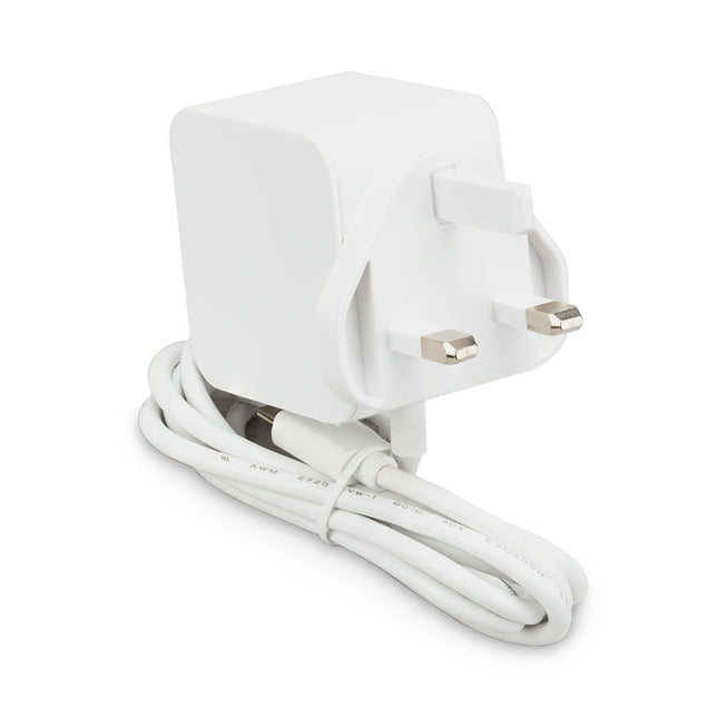
The Raspberry Pi 27 W PD USB-C power supply is designed specifically to power the Raspberry Pi 5. It is also capable of delivering 5 V/3 A, 9 V/3 A, 12 V/2.25 A, 15 V/1.8 A to PD-compatible products, making it a good and cost-effective power supply for many general applications, such as charging smartphones and tablets.
Specifications
Input
100-240 V AC
Output
5 A @ 5.1 V, 3 A @ 9 V, 2.25 A @ 12 V, 1.8 A @ 15 V
Connector
USB-C
Length
1.2 m
Color
White
Region
UK
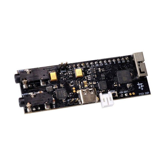
PÚCA DSP is an open-source, Arduino-compatible ESP32 development board for audio and digital signal processing (DSP) applications with expansive audio-processing features. It provides audio inputs, audio outputs, a low-noise microphone array, an integrated test-speaker option, additional memory, battery-charge management, and ESD protection all on a small, breadboard-friendly PCB.
Synthesizers, Installations, Voice UI, and More
PÚCA DSP can be used for a wide range of DSP applications, including but not limited to those in the fields of music, art, creative technology, and adaptive technology. Music-related examples include digital-music synthesis, mobile recording, Bluetooth speakers, wireless line-level directional microphones, and the design of smart musical instruments. Art-related examples include acoustic sensor networks, sound-art installations, and Internet-radio applications. Examples related to creative and adaptive technology include voice user interface (VUI) design and Web audio for the Internet of Sounds.
Compact, Integrated Design
PÚCA DSP was designed for portability. When used with an external 3.7 V rechargeable battery, it can be deployed almost anywhere or integrated into just about any device, instrument, or installation. Its design emerged from months of experimentation with various ESP32 development boards, DAC breakout boards, ADC breakout boards, Microphone breakout boards, and audio-connector breakout boards, and – despite its diminutive size – it manages to provide all of that functionality in a single board. And it dos so without compromising signal quality.
Specifications
Processor & Memory
Espressif ESP32 Pico D4 Processor
32-bit dual core 80 MHz / 160 MHz / 240 MHz
4 MB SPI Flash with 8 MB additional PSRAM (Original Edition)
Wireless 2.4 GHz Wi-Fi 802.11b/g/n
Bluetooth BLE 4.2
3D Antenna
Audio
Wolfson WM8978 Stereo Audio Codec
Audio Line In on 3.5 mm stereo onnector
Audio Headphone / Line Out on 3.5 mm stereo connector
Stereo Aux Line In, Audio Mono Out routed to GPIO Header
2x Knowles SPM0687LR5H-1 MEMS Microphones
ESD protection on all audio inputs and outputs
Support for 8, 11.025, 12, 16, 22.05, 24, 32, 44.1 and 48 kHz sample rates
1 W Speaker Driver, routed to GPIO Header
DAC SNR 98 dB, THD -84 dB (‘A’ weighted @ 48 kHz)
ADC SNR 95 dB, THD -84 dB (‘A’ weighted @ 48 kHz)
Line input impedance: 1 MOhm
Line output impedance: 33 Ohm
Form Factor and Connectivity
Breadboard friendly
70 x 24 mm
11x GPIO pins broken out to 2.54 mm pitch header, with access to both ESP32 ADC channels, JTAG and capacitive touch pins
USB 2.0 over USB Type C connector
Power
3.7/4.2 V Lithium Polymer Rechargeable Battery, USB or external 5 V DC power source
ESP32 and Audio Codec can be placed into low power modes under software control
Battery voltage level detection
ESD protection on USB data bus
Downloads
GitHub
Datasheet
Links
Crowd Supply Campaign (includes FAQs)
Hardware Overview
Programming the Board
The Audio Codec
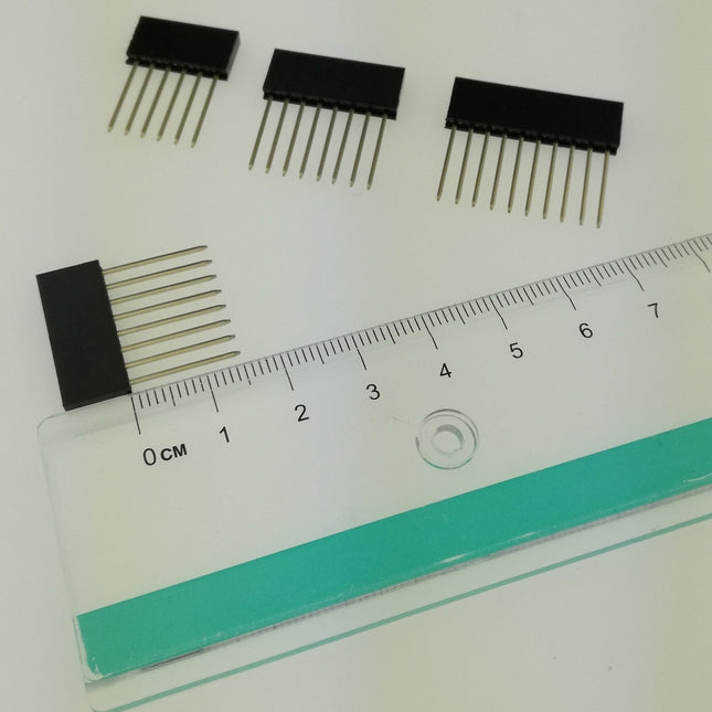
With a 6x20 grid of 2.54 mm spaced holes for easy soldering and labelled Pico pins so you know what's what, Pico Proto is perfect for when you're happy with your breadboard project and want to give it a secure, smart and compact long-term home.
Pico Proto doesn't come with any headers attached, so you will need to either solder it directly to your Pico's male header pins (for a permanent, but super slim sandwich) or solder it to some female header.
Features
40 2.54 mm spaced holes for attaching to your Pico.
120 2.54 mm spaced holes (6x20 grid) for attaching other things
Compatible with Raspberry Pi Pico.
Dimensions: approx 51 x 25 x 1 mm (L x W x H)
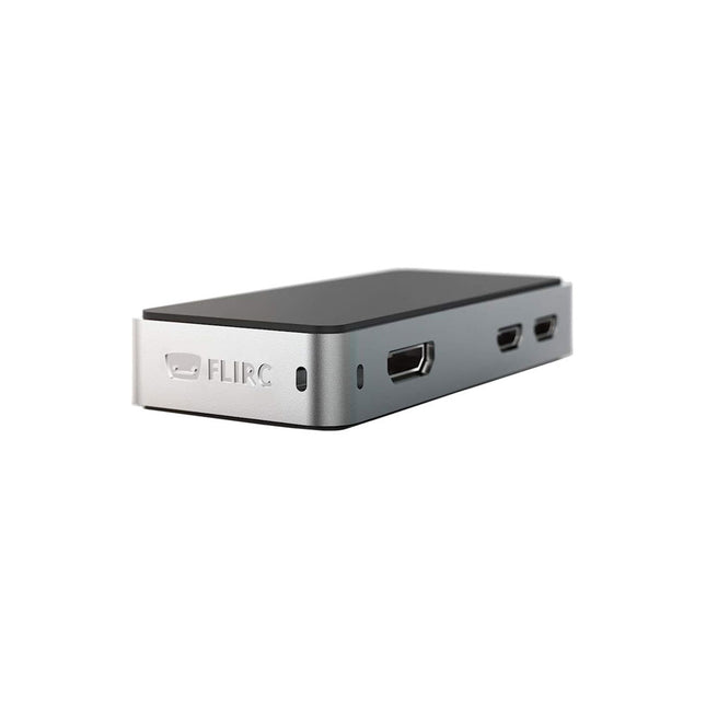
The FLIRC Raspberry Pi Zero Case is compatible with Raspberry Pi Zero W and the newer Raspberry Pi Zero 2 W.
The design of the FLIRC Zero Case is based on the original FLIRC case. As with the original, the aluminum housing serves as protection and, thanks to the contact point on the processor, as a passive cooler. Ideal for silent operation.
In addition to a normal cover that encloses and protects the Raspberry Pi Zero, there is a second cover that allows access to the GPIO pins through a small opening.