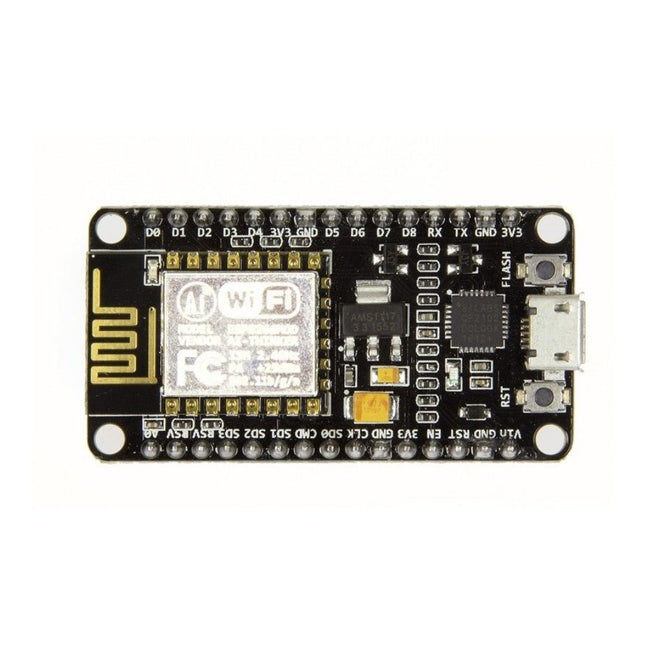
Note: NodeMCU is the name of both a firmware and a boardNodeMCU is an open source IoT platform, whose firmware runs on Espressif's SoC Wi-Fi ESP8266, based on the ESP8266 nonOS SDK. Its hardware is based on the ESP-12 module. The scripting language is Lua which allows to use many open source projects like lua-cjson and spiffs. Features Wi-Fi Module – ESP-12E module similar to ESP-12 module but with 6 extra GPIOs. USB – micro USB port for power, programming and debugging Headers – 2x 2.54 mm 15-pin header with access to GPIOs, SPI, UART, ADC, and power pins Reset & Flash buttons Power: 5V via micro USB port Dimensions: 49 x 24.5 x 13 mm
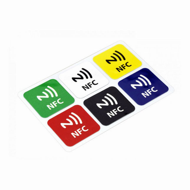
Features NFC chip material: PET + Etching antenna Chip: NTAG216 (compatible with all NFC phones) Frequency: 13.56 MHz (High Frequency) Reading time: 1 - 2 ms Storage capacity: 888 bytes Read and write times: > 100,000 times Reading distance: 0 - 5 mm Data retention: > 10 years NFC chip size: Diameter 30 mm Non-contact, no friction, the failure rate is small, low maintenance costs Read rate, verification speed, which can effectively save time and improve efficiency Waterproof, dustproof, anti-vibration No power comes with an antenna, embedded encryption control logic, and communication logic circuit Included 1x NFC Stickers (6-color kit)
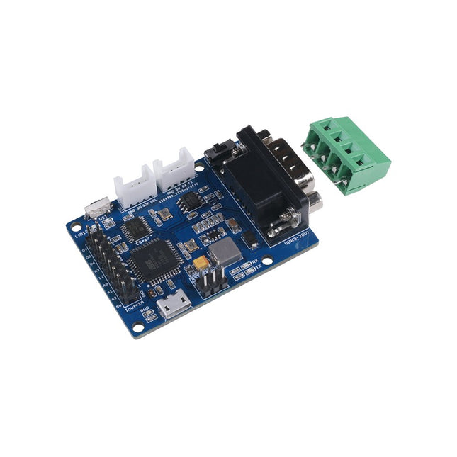
The Seeed Studio CANBed – Arduino CAN-BUS Development Kit integrates an ATmega32U4 microcontroller, eliminating the need for an external Arduino board. It combines an MCP2515 CAN Bus controller and an MCP2551 CAN Bus transceiver on a single board, providing a compact and reliable CAN communication solution.
Features
ATmega32U4 with Arduino Leonardo bootloader on the board
MCP2515 CAN Bus controller and MCP2551 CAN Bus transceiver
OBD-II and CAN standard pinout selectable at the sub-D connector
Compatible with Arduino IDE
Parameter
Value
MCU
ATmega32U4(with Arduino Leonardo bootloader)
Clock Speed
16 MHz
Flash Memory
32 KB
SRAM
2.5 KB
EEPROM
1 KB
Operate Voltage (CAN-BUS)
9 V - 28 V
Operate Voltage (MicroUSB)
5 V
Input Interface
sub-D
Included
CANBed PCBA
sub-D connector
4PIN Terminal
2x 4PIN 2.0 Connector
1x 9x2 2.54 Header
1x 3x2 2.54 Header
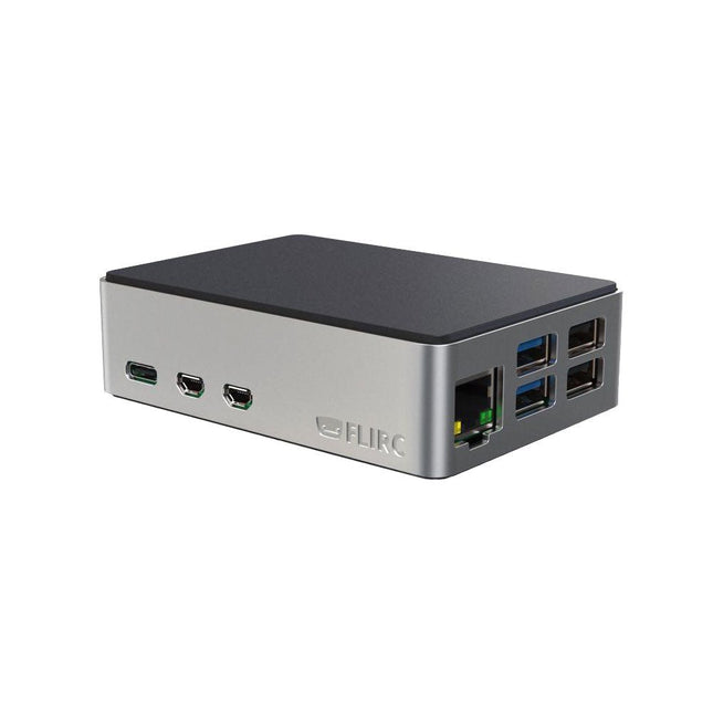
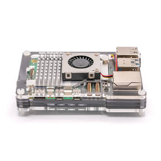
Discover the perfect case for your Raspberry Pi 5. FLIRC has made the power button accessible and improved it with LED support. Enjoy the familiar aluminium core heatsink you've come to love, nestled between two matte black soft-touch panels. Customised to fit into your entertainment system. Built-in Heat Sink This is the first affordable Raspberry Pi case made from aluminium. FLIRC wanted to ensure that form didn't take precedence over function, so they used the aluminium body of the case as a built-in heat sink. Included with the case is a thermal pad and 4 screws for easy assembly. Stability and Access FLIRC has built in rubber feet to elevate the case so that it simply floats under your TV. In addition to the built-in heatsink, small ventilation slots on the bottom ensure that the Raspberry Pi stays cool. The GPIO pins are accessible via the slot at the bottom of the case, and the SD card does not need to be disassembled to reach them. Power Button and LED Support The power button of the Raspberry Pi 5 is natively supported by the FLIRC housing. The activity LEDs are also clearly visible.
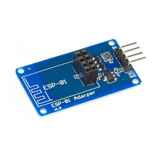
The ESP-01 Adapter 3.3-5 V is the ideal solution for connecting an ESP-01 ESP8266 module to a 5 V system such as Arduino Uno.
Features
Adapter module for ESP-01 Wi-Fi module
3.3 V voltage regulator circuit & onboard level conversion for easy use of 5 V microcontroller with ESP-01 Wi-Fi module
Compatible with Uno R3
4.5~5.5 V (on-board 3.3 V LDO Regulator)
Interface logic voltage: 3.3-5 V compatible (on-board level shift)
Current: 0-240 mA
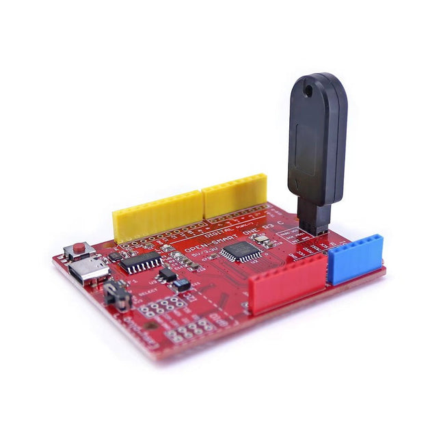
This programmer is specifically designed for burning bootloaders (without a computer) on Arduino-compatible ATmega328P/ATmega328PB development boards.
Simply plug the programmer into the ICSP interface to re-burn the bootloader. It’s also compatible with new chips, provided the IC is functional.
Note: Burning a bootloader erases all previous chip data.
Features
Working voltage: 3.1-5.3 V
Working current: 10 mA
Compatible with Arduino Uno R3 based boards (ATmega328P or ATmega328PB)
Dimensions: 39.6 x 15.5 x 7.8 mm
The slim, hackable and attractive case for Raspberry Pi 5.
Pibow 5 lets you access all the ports and connectors on your Raspberry Pi and even has a clever little tab that will let you push the Pi 5's brand new power button whilst it's safely ensconced in its case. The case is designed to fit neatly around Raspberry Pi's Active Cooler.
Features
Compatible with Raspberry Pi 5 Official Active Cooler
Super-slimline profile
Fully HAT/pHAT compatible
Protects your Raspberry Pi 5
Clear top leaves Raspberry Pi 5 visible (so you can gaze upon its wonder).
GPIO cut-out
Leaves all ports and connectors accessible
External Power Button Nubbin via compliant mechanism magic
Mounting holes on the base that will accommodate M2.5 screws/bolts and the studs on popular Danish ABS construction blocks
Made from lightweight high-quality cast acrylic
Great for hacking and tinkering
Crafted out of five unique layers including a transparent top that leaves your Raspberry Pi visible inside. Each layer is laser-cut from colourful high-quality cast acrylic and once stacked they securely contain a Raspberry Pi 5 while leaving the primary ports and GPIO accessible.
This case is lightweight and ideal for mounting to any surface. No tools are required for assembly or disassembly!
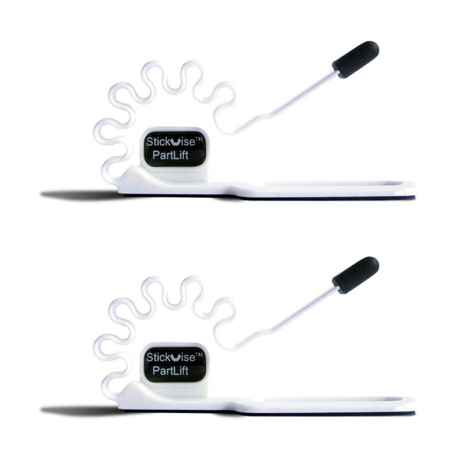
An easy way to hold parts to the bottom of a PCB while soldering
PartLift holds thru hole parts in place to free up your hands while you solder the legs. A simple but useful tool to go along with your Stickvise. The base pad is non-slip silicone foam, the body of the tool is ABS which provides very light spring tension to hold your part in place. The tip of the tool is made from high temperature silicone that withstands soldering temperatures without being damaged.
Features
PartLift holds thru hole parts in place during soldering
Use with a Stickvise or any low profile PCB holder
The tip is silicone that withstands soldering temperatures
The base pad is non-slip silicone foam
Specifications
Material
Silicone
Dimensions
109 x 40 x 40 mm
Weight
59 g
Raspberry Pi 5 provides two four-lane MIPI connectors, each of which can support either a camera or a display. These connectors use the same 22-way, 0.5 mm-pitch “mini” FPC format as the Compute Module Development Kit, and require adapter cables to connect to the 15-way, 1 mm-pitch “standard” format connectors on current Raspbery Pi camera and display products.These mini-to-standard adapter cables for cameras and displays (note that a camera cable should not be used with a display, and vice versa) are available in 200 mm, 300 mm and 500 mm lengths.
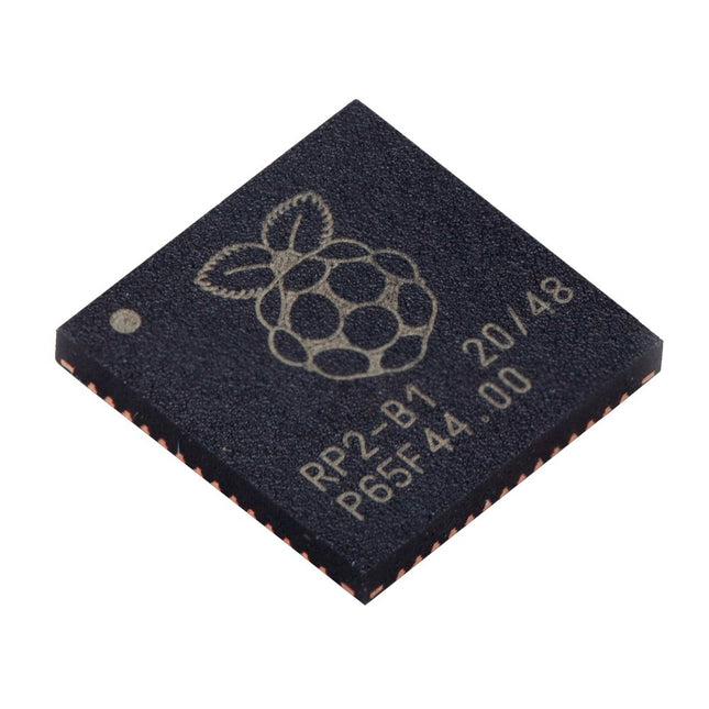
Specifications
Dual ARM Cortex-M0+ @ 133 MHz
264 kB on-chip SRAM in six independent banks
Support for up to 16 MB of off-chip Flash memory via dedicated QSPI bus
DMA controller
Fully-connected AHB crossbar
Interpolator and integer divider peripherals
On-chip programmable LDO to generate core voltage
2x on-chip PLLs to generate USB and core clocks
30x GPIO pins, 4 of which can be used as analogue inputs
Peripherals
2x UARTs
2x SPI controllers
2x I²C controllers
16x PWM channels
USB 1.1 controller and PHY, with host and device support
8x PIO state machines
What you'll get
10x bare RP2040 chips
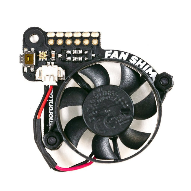
When Raspberry Pi 4's system on chip (SoC) achieves a certain temperature, it lowers its operating speed to protect itself from harm. As a result, you don't get maximum performance from the single board computer. Fan SHIM is an affordable accessory that effectively eliminates thermal throttling and boosts the performance of RPi 4. It's quite easy to attach the fan SHIM to Raspberry pi: fan SHIM uses a friction-fit header, so it just slips onto your Pi's pins and it's ready to go, no soldering required! The fan can be controlled in software, so you can adjust it to your needs, for example, toggle it on when the CPU reaches a certain temperature etc. You can also program the LED as a visual indicator of the fan status. The tactile switch can also be programmed, so you can use it to toggle the fan on or off, or to switch between temperature-triggered or manual mode. Features 30 mm 5 V DC fan 4,200 RPM 0.05 m³/min air flow 18.6 dB acoustic noise (whisper-quiet) Friction-fit header No soldering required RGB LED (APA102) Tactile switch Basic assembly required Compatible with Raspberry Pi 4 (and 3B+, 3A+)
Python library and daemon Pinout Scope of delivery Fan SHIM PCB 30 mm 5 V DC fan with JST connector M2.5 nuts and bolts Assembly The assembly is really simple and almost takes no time With the component side of the PCB facing upwards, push the two M2.5 bolts through the holes from below, then screw on the first pair of nuts to secure them and act as spacers. Push the fan's mounting holes down onto the bolts, with the cable side of the fan downwards (as pictured) and the text on the fan upwards. Attach with another two nuts. Push the fan's JST connector into the socket on Fan SHIM. Software With the help of Python library you can control the fan (on/off), RGB LED, and switch. You'll also find a number of examples that demonstrate each feature, as well as a script to install a daemon (a computer program that runs as a background process) that runs the fan in automatic mode, triggering it on or off when the CPU reaches a threshold temperature, with a manual override via the tactile switch.
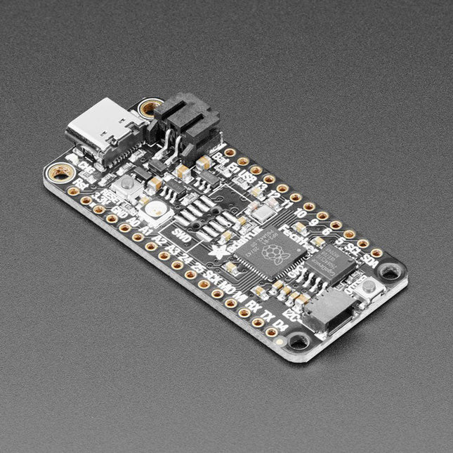
Inside the RP2040 is a 'permanent ROM' USB UF2 bootloader. What that means is when you want to program new firmware, you can hold down the BOOTSEL button while plugging it into USB (or pulling down the RUN/Reset pin to ground) and it will appear as a USB disk drive you can drag the firmware onto. Folks who have been using Adafruit products will find this very familiar – Adafruit uses the technique on all thier native-USB boards. Just note you don't double-click reset, instead hold down BOOTSEL during boot to enter the bootloader!
The RP2040 is a powerful chip, which has the clock speed of our M4 (SAMD51), and two cores that are equivalent to our M0 (SAMD21). Since it is an M0 chip, it does not have a floating point unit, or DSP hardware support – so if you're doing something with heavy floating-point math, it will be done in software and thus not as fast as an M4. For many other computational tasks, you'll get close-to-M4 speeds!
For peripherals, there are two I²C controllers, two SPI controllers, and two UARTs that are multiplexed across the GPIO – check the pinout for what pins can be set to which. There are 16 PWM channels, each pin has a channel it can be set to (ditto on the pinout).
Specifications
Measures 2.0 x 0.9 x 0.28' (50.8 x 22.8 x 7 mm) without headers soldered in
Light as a (large?) feather – 5 grams
RP2040 32-bit Cortex M0+ dual core running at ~125 MHz @ 3.3 V logic and power
264 KB RAM
8 MB SPI FLASH chip for storing files and CircuitPython/MicroPython code storage. No EEPROM
Tons of GPIO! 21 x GPIO pins with following capabilities:
Four 12 bit ADCs (one more than Pico)
Two I²C, Two SPI and two UART peripherals, one is labeled for the 'main' interface in standard Feather locations
16 x PWM outputs - for servos, LEDs, etc
The 8 digital 'non-ADC/non-peripheral' GPIO are consecutive for maximum PIO compatibility
Built in 200 mA+ lipoly charger with charging status indicator LED
Pin #13 red LED for general purpose blinking
RGB NeoPixel for full color indication.
On-board STEMMA QT connector that lets you quickly connect any Qwiic, STEMMA QT or Grove I²C devices with no soldering!
Both Reset button and Bootloader select button for quick restarts (no unplugging-replugging to relaunch code)
3.3 V Power/enable pin
Optional SWD debug port can be soldered in for debug access
4 mounting holes
24 MHz crystal for perfect timing.
3.3 V regulator with 500mA peak current output
USB Type C connector lets you access built-in ROM USB bootloader and serial port debugging
RP2040 Chip Features
Dual ARM Cortex-M0+ @ 133 MHz
264 kB on-chip SRAM in six independent banks
Support for up to 16 MB of off-chip Flash memory via dedicated QSPI bus
DMA controller
Fully-connected AHB crossbar
Interpolator and integer divider peripherals
On-chip programmable LDO to generate core voltage
2 on-chip PLLs to generate USB and core clocks
30 GPIO pins, 4 of which can be used as analog inputs
Peripherals
2 UARTs
2 SPI controllers
2 I²C controllers
16 PWM channels
USB 1.1 controller and PHY, with host and device support
8 PIO state machines
Comes fully assembled and tested, with the UF2 USB bootloader. Adafruit also tosses in some header, so you can solder it in and plug it into a solderless breadboard.
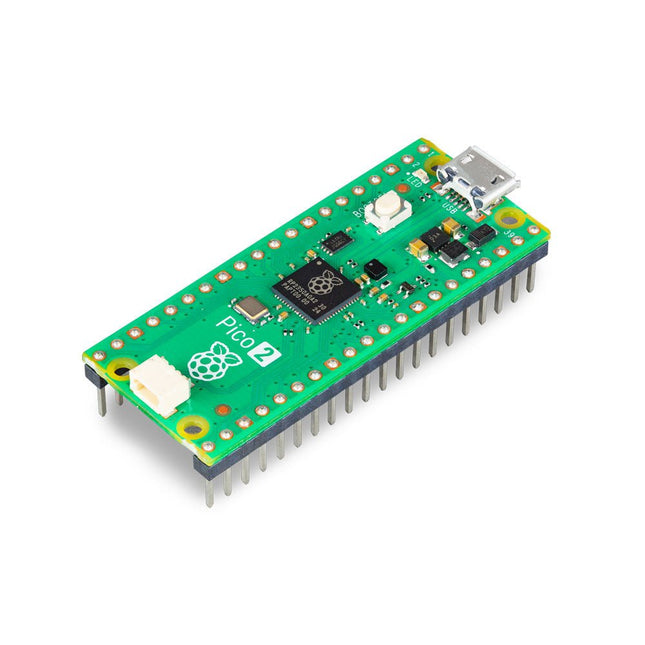
The Raspberry Pi Pico 2 H (with Headers) is a new microcontroller board from the Raspberry Pi Foundation, based on the RP2350. It features a higher core clock speed, double the on-chip SRAM, double the on-board flash memory, more powerful Arm cores, optional RISC-V cores, new security features, and upgraded interfacing capabilities. The Raspberry Pi Pico 2 H offers a significant boost in performance and features while maintaining hardware and software compatibility with earlier members of the Raspberry Pi Pico series.
The RP2350 provides a comprehensive security architecture built around Arm TrustZone for Cortex-M. It incorporates signed boot, 8 KB of antifuse OTP for key storage, SHA-256 acceleration, a hardware TRNG, and fast glitch detectors.
The unique dual-core, dual-architecture capability of the RP2350 allows users to choose between a pair of industry-standard Arm Cortex-M33 cores and a pair of open-hardware Hazard3 RISC-V cores. Programmable in C/C++ and Python, and supported by detailed documentation, the Raspberry Pi Pico 2 is the ideal microcontroller board for both enthusiasts and professional developers.
Specifications
CPU
Dual Arm Cortex-M33 or dual RISC-V Hazard3 processors @ 150 MHz
Memory
520 KB on-chip SRAM; 4 MB on-board QSPI flash
Interfaces
26 multi-purpose GPIO pins, including 4 that can be used for AD
Peripherals
2x UART
2x SPI controllers
2x I²C controllers
24x PWM channels
1x USB 1.1 controller and PHY, with host and device support
12x PIO state machines
Input power
1.8-5.5 V DC
Dimensions
21 x 51 mm
Downloads
Datasheet (Pico 2)
Datasheet (RP2350)
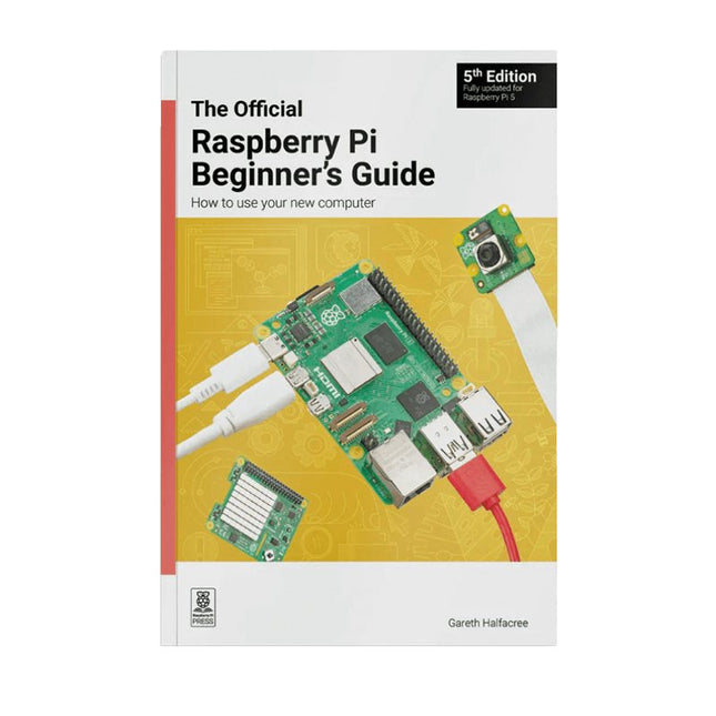
Fully updated for Raspberry Pi 5
Raspberry Pi is a small, clever, British-built computer that's packed with potential. Made using a desktop-class, energy-efficient processor, Raspberry Pi is designed to help you learn coding, discover how computers work, and build your own amazing things. This book was written to show you just how easy it is to get started.
Learn how to:
Set up your Raspberry Pi, install its operating system, and start using this fully functional computer.
Start coding projects, with step-by-step guides using the Scratch 3, Python, and MicroPython programming languages.
Experiment with connecting electronic components, and have fun creating amazing projects.
New in the 5th edition:
Updated for the latest Raspberry Pi computers: Raspberry Pi 5 and Raspberry Pi Zero 2 W.
Covers the latest Raspberry Pi OS.
Includes a new chapter on the Raspberry Pi Pico.
Downloads
GitHub
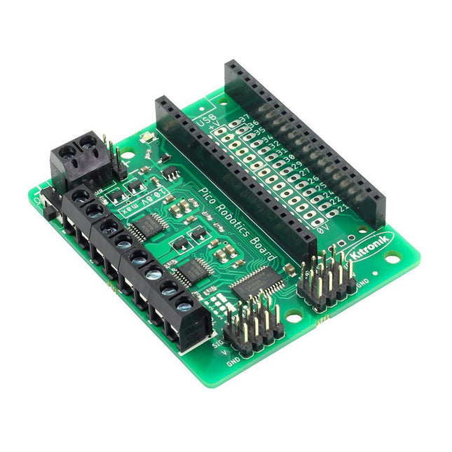
The Robotics Board features 2 Dual H Bridge Motor Driver ICs. These are capable of driving 2 standard motors or 1 stepper motor each, with full forward, reverse, and stop control. There are also 8 servo outputs, capable of driving standard and continuous rotation servos. They can all be controlled by the Pico using the I²C protocol, via a 16 channel driver IC. The IO break out provides connections to all the unused pins on the Pico. The 27 available I/O pins allow other devices, such as sensors or ZIP LEDs, to be added to the board. Power is provided via either a terminal block or servo style connector. The supply is then controlled by an on/off power switch to the board and there is also a green LED to indicate when the board has power. The board then produces a regulated 3.3V supply which is fed into the 3 V and GND connections to power the connected Pico. This removes the need to power the Pico separately. The 3 V and GND pins are also broken out on the header, which means external devices can also be powered. To use the robotics board, the Pico should be firmly inserted into the dual row pin socket on the board. Ensure the Pico is inserted with the USB connector at the same end as the power connectors on the robotics board. This will allow access to all of the board functions and each pin is broken out. Features A compact yet feature-packed board designed to sit at the heart of your Raspberry Pi Pico robotics projects. The board can drive 4 motors (or 2 stepper motors) and 8 servos, with full forward, reverse, and stop control. It also features 27 other I/O expansion points and Power and Ground connections. The I²C communication lines are also broken out allowing other I²C compatible devices to be controlled. This board also features an on/off switch and power status LED. Power the board via either a terminal block or servo style connector. The 3V and GND pins are also broken out on the Link header, allowing external devices to be powered. Code it with MicroPython or via an editor such as the Thonny editor. 1 x Kitronik Compact Robotics Board for Raspberry Pi Pico Dimensions: 68 x 56 x 10 mm Requires Raspberry Pi Pico board
Raspberry Pi Pico Wireless Pack attaches to the back of your Pico and uses an ESP32 chip to let your Pico connect to 2.4 GHz wireless networks and transfer data. There's a microSD card slot for if you want to store lots of data locally as well as a RGB LED (for status updates) and a button (useful for things like enabling/disabling Wi-Fi).
Great for quickly adapting an existing Pico project to have wireless functionality, Raspberry Pi Pico Wireless Pack would come in handy for sending sensor data into home automation systems or dashboards, for hosting a web page from a matchbox or for letting your Pico interact with online APIs.
Features
ESP32-WROOM-32E module for wireless connectivity (connected via SPI) (datasheet)
1x Tactile button
RGB LED
Micro-SD card slot
Pre-soldered female headers for attaching your Raspberry Pi Pico
Fully assembled
No soldering required (as long as your Pico has header pins attached)
Compatible with Raspberry Pi Pico
Dimensions: approx 53 x 25 x 11 mm (L x W x H, including headers and components)
C++ and MicroPython libraries
Use your Raspberry Pi with LTE Cat-4 4G/3G/2G Communication & GNSS Positioning, for remote data transmission/phone/SMS, suitable for remote area monitoring/alarming.
This 4G hat is based on the Maduino Zero 4G LTE, but without any controller. It needs to work with Raspberry Pi (2x20 connector and USB). The Raspberry communicate with this HAT with simple AT commands (via the TX/RX Pins in the 2X20 connector) for simple controls, such as SMS/Phone/GNSS; with the USB connecting and proper Linux driver installed, the 4G hat act as a 4G network adapter, that can access to the Internet and transmit data with 4G protocol.
Compares to normal USB 4G dongle, this Raspberry Pi 4G Hat has the following advantages:
Onboard Audio codec, that you can have a call directly with your RPI, or auto broadcasting with a loudspeaker;
Hardware UART communication, hardware controlling of Power(by 2s pulse of PI GPIO or POWERKEY button), hardware controlling of flight mode;
Dual LTE 4G antenna, plus GPS antenna
Features
LTE Cat-4, with uplink rate 50 Mbps and downlink rate 150 Mbps
GNSS Positioning
Audio Driver NAU8810
Supports dial-up, phone, SMS, TCP, UDP, DTMF, HTTP, FTP, and so on
Supports GPS, BeiDou, Glonass, LBS base station positioning
SIM card slot, supports 1.8V/3V SIM card
Onboard audio jack and audio decoder for making a telephone call
2x LED indicators, easy to monitor the working status
Supports SIM application toolkit: SAT Class 3, GSM 11.14 Release 99, USAT
Included
1x 4G LTE Hat For Raspberry Pi
1x GPS antenna
2x 4G LTE antenna
2x Standoff
Downloads
GitHub
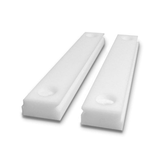
An upgraded jaw set that withstands direct contact with a soldering iron
Stickvise High Temperature PTFE Vise Jaws will withstand accidental contact with a soldering iron and will not melt. These are a great upgrade for your Stickvise.
Features
Made from PTFE with extremely high melting point
Withstands incidental contact with a soldering iron
This is the jaw plates only, does not include a Stickvise
Specifications
Material
Aluminum
Dimensions
73 x 53 x 3 mm
Weight
21 g
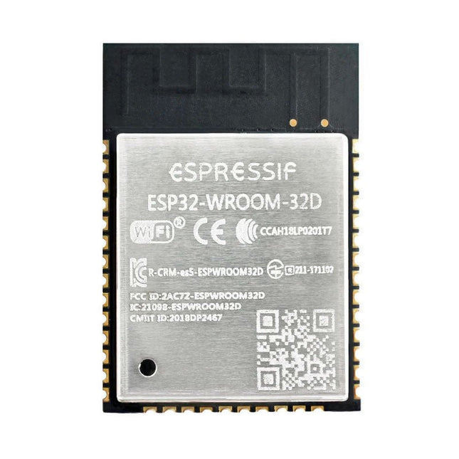
The ESP32-WROOM-32, measuring 25.2 x 18 mm only, contains the ESP32 SoC, flash memory, precision discrete components, and PCB antenna to provide outstanding RF performance in space-constrained applications.
ESP32-WROOM-32 is a powerful, generic Wi-Fi + BT + BLE MCU module that targets a wide variety of applications, ranging from low-power sensor networks to the most demanding tasks, such as voice encoding, music streaming and MP3 decoding.
At the core of this module is the ESP32-D0WDQ6 chip. The chip embedded is designed to be scalable and adaptive. There are two CPU cores that can be individually controlled, and the clock frequency is adjustable from 80 MHz to 240 MHz. The user may also power off the CPU and make use of the low-power co-processor to monitor the peripherals for changes or crossing of thresholds constantly. ESP32 integrates a rich set of peripherals, ranging from capacitive touch sensors, Hall sensors, SD card interface, Ethernet, high-speed SPI, UART, I²S and I²C.
The integration of Bluetooth, Bluetooth LE and Wi-Fi ensures that a wide range of applications can be targeted and that the module is future proof. Using Wi-Fi allows a vast physical range and direct connection to the internet through a Wi-Fi router while using Bluetooth allows the user to conveniently connect to the phone or broadcast low energy beacons for its detection.
The sleep current of the ESP32 chip is less than 5 µA, making it suitable for battery powered and wearable electronics applications. ESP32 supports a data rate of up to 150 Mbps, and 20.5 dBm output power at the antenna to ensure the broadest physical range. As such the chip does offer industry-leading specifications and the best performance for electronic integration, range, power consumption, and connectivity.
Downloads
Datasheet
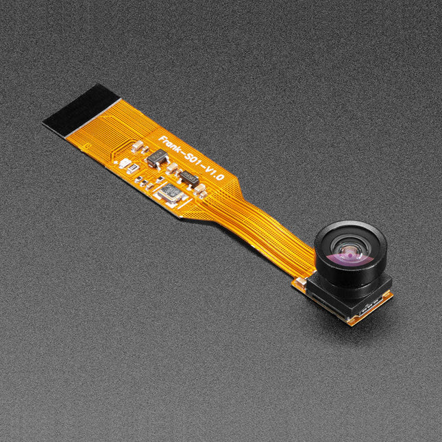
Is your house haunted? Or, rather, are you convinced that your house is haunted but have never been able to prove it since you've never had a camera that integrated with your Raspberry Pi Zero but was still small enough that the ghosts wouldn't notice it?
Luckily, the spy camera for Raspberry Pi Zero is smaller than a thumbnail with a high enough resolution to see people, ghosts, or whatever it is you're looking for. It's about the size of a cell phone camera – the module being just 8.6 x 8.6 mm – with only a 2' cable, so you can create an extra compact and sneaky little spy cam. It has a 160-degree focal angle for a very wide/distorted fisheye effect that's great for security systems or watching a big swath of the living room or roadway.
Like the Raspberry Pi camera board, it attaches to your Raspberry Pi Zero v1.3 or Zero W by way of the small socket on the board's edge closest to the 'PWR in' port. This interface uses the dedicated CSI interface, which was designed especially for interfacing to cameras. The CSI bus is capable of extremely high data rates, and it exclusively carries pixel data.
The camera is connected to the BCM2835 processor on the RPi via the CSI bus, a higher bandwidth link which carries pixel data from the camera back to the processor. This bus travels along the ribbon cable that attaches the camera board to the Pi. The ribbon cables are compatible with both the RPi Zero v1.3 and RPi Zero W.
The sensor itself has a native resolution of 5 megapixels and has a fixed focus lens onboard. It has similar specs as the original RPi camera, but is not as high-res as the new RPi camera v2!
Specifications
Camera Module Dimensions: 8.6 x 8.6 mm
Lens Diameter: 10 mm
Total Length: 60 mm
Lens Focal Angle: 160 degrees
Weight: 1.9 g
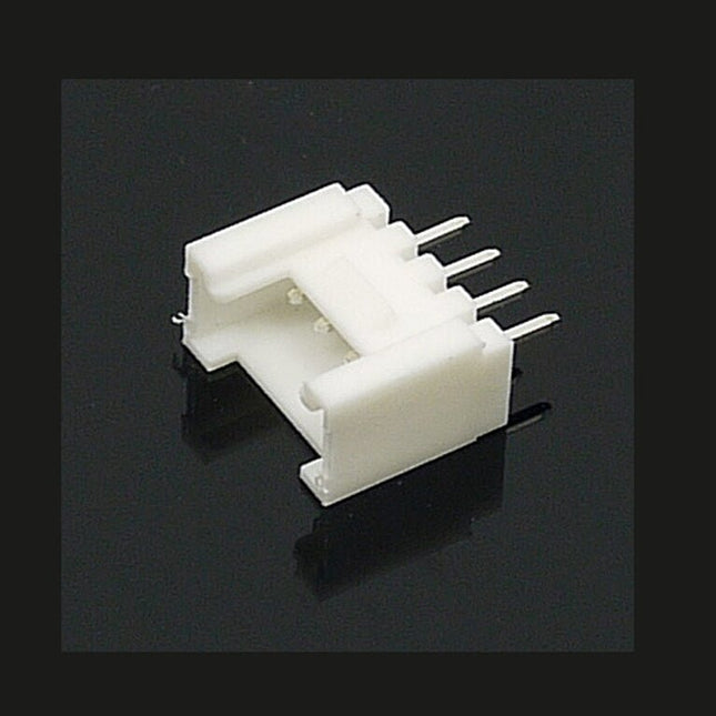
The universal 4 Pin connector is a white 4-pin buckled connector used on Stem, Twigs and Grove cables. The pin spacing is 2 mm. There are 10 connectors per bag. They can be used in DIY projects.
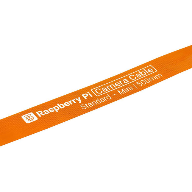
Raspberry Pi 5 provides two four-lane MIPI connectors, each of which can support either a camera or a display. These connectors use the same 22-way, 0.5 mm-pitch “mini” FPC format as the Compute Module Development Kit, and require adapter cables to connect to the 15-way, 1 mm-pitch “standard” format connectors on current Raspbery Pi camera and display products.These mini-to-standard adapter cables for cameras and displays (note that a camera cable should not be used with a display, and vice versa) are available in 200 mm, 300 mm and 500 mm lengths.
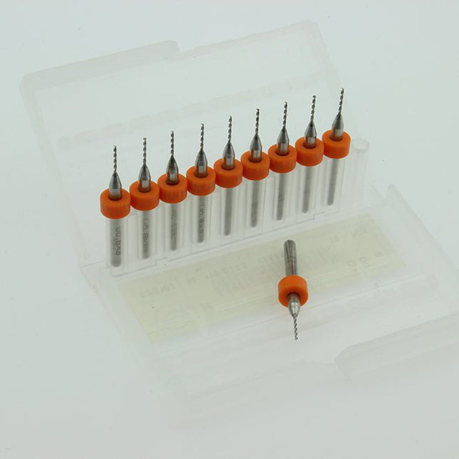
Cleaning nozzle drill kit small box containing 10 carbide PCB drills 0.8 mm all with 4 mm shaft.
Ideal for drilling small precision holes in pcb's, plastic or soft metal.
Features
Universal pen for use on almost all surfaces
Suitable for overhead projection
Also suitable for use on CDs/DVDs
Excellent smudge-proof and waterproof qualities on almost all surfaces
Dries in seconds, therefore ideal for left-handed users
Permanent, low-odour ink
Lightfast colours: black, brown
Weatherproof colour black
Stand-up STAEDTLER box
PP barrel and cap guarantee long service life
DRY SAFE – can be left uncapped for days without drying up (Standard atmosphere according to ISO 554)
Airplane-safe - automatic pressure equalization prevents pen from leaking on board aircraft
Xylene and toluene-free ink
Superb colour brilliancy
Line width superfine approx. 0.4 mm
Refillable