
Physical Products
-
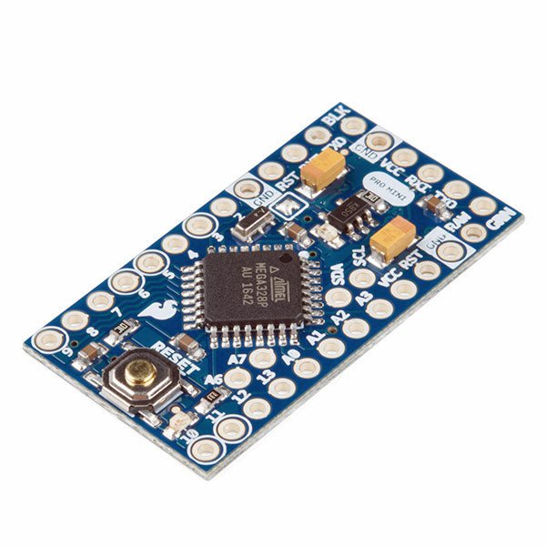
SparkFun SparkFun Arduino Pro Mini 328 (5 V, 16 MHz)
The Arduino Pro Mini is a microcontroller board based on the ATmega328P. It has 14 digital input/output pins (of which 6 can be used as PWM outputs), 6 analog inputs, an on-board resonator, a reset button, and holes for mounting pin headers. A six pin header can be connected to an FTDI cable or SparkFun breakout board to provide USB power and communication to the board. The Arduino Pro Mini is intended for semi-permanent installation in objects or exhibitions. The board comes without pre-mounted headers, allowing the use of various types of connectors or direct soldering of wires. The pin layout is compatible with the Arduino Mini. The Arduino Pro Mini was designed and is manufactured by SparkFun Electronics. Specifications Microcontroller ATmega328P Board Power Supply 5-12 V Circuit Operating Voltage 5 V Digital I/O Pins 14 PWM Pins 6 UART 1 SPI 1 I²C 1 Analog Input Pins 6 External Interrupts 2 DC Current per I/O Pin 40 mA Flash Memory 32 KB of which 2 KB used by bootloader SRAM 2 KB EEPROM 1 KB Clock Speed 16 MHz Dimensions 18 x 33.3 mm (0.7 x 1.3") Downloads Eagle files Schematics
€ 14,95€ 7,95Best Price
-
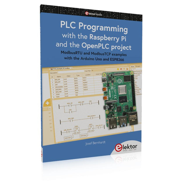
Elektor Publishing PLC Programming with the Raspberry Pi and the OpenPLC Project
ModbusRTU and ModbusTCP examples with the Arduino Uno and ESP8266 Introduction to PLC programming with OpenPLC, the first fully open source Programmable Logic Controller on the Raspberry Pi, and Modbus examples with Arduino Uno and ESP8266 PLC programming is very common in industry and home automation. This book describes how the Raspberry Pi 4 can be used as a Programmable Logic Controller. Before taking you into the programming, the author starts with the software installation on the Raspberry Pi and the PLC editor on the PC, followed by a description of the hardware. You'll then find interesting examples in the different programming languages complying with the IEC 61131-3 standard. This manual also explains in detail how to use the PLC editor and how to load and execute the programs on the Raspberry Pi. All IEC languages are explained with examples, starting with LD (Ladder Diagram) over ST (Structured Control Language) to SFC (Special Function Chart). All examples can be downloaded from the author's website. Networking gets thorough attention too. The Arduino Uno and the ESP8266 are programmed as ModbusRTU or ModbusTCP modules to get access to external peripherals, reading sensors and switching electrical loads. I/O circuits complying with the 24 V industry standard may also be of interest for the reader. The book ends with an overview of commands for ST and LD. After reading the book, the reader will be able to create his own controllers with the Raspberry Pi.
€ 39,95
Members: € 35,96
-
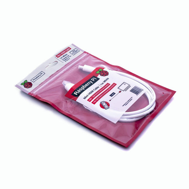
Raspberry Pi Foundation Official Mini-HDMI Cable for Raspberry Pi Zero
The official Raspberry Pi mini-HDMI to HDMI (A/M) cable designed for all Raspberry Pi Zero models. 19-pin HDMI Type D(M) to 19-pin HDMI Type A(M) 1 m cable (white) Nickel-plated plugs 4Kp60 compliant RoHS compliant 3 Mohm 300 VDC insulation, withstands 300 VDC for 0.1s
-
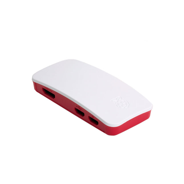
Raspberry Pi Foundation Official Case for Raspberry Pi Zero
The case consists of two parts. It has a standard base featuring a cut-out to allow access to the GPIO, and a choice of three lids: a plain lid, a GPIO lid (allowing access to the GPIO from above), and a camera lid (which, when used with the short camera cable supplied, allows the Raspberry Pi Camera or Camera Noir to be fitted neatly inside it). Included 1x base 3x lids (plain, GPIO, camera) 1x short camera cable 4x rubber feet
-
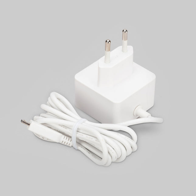
Raspberry Pi Foundation Official Micro-USB Power Supply for Raspberry Pi
Official Micro-USB Power Supply for Raspberry Pi (12.5 W) Input: 100-240 VAC Output: 5.1 V / 2.5 A power supply Connector: micro USB Length: 1.5 m
-
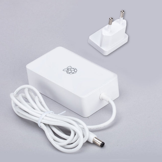
Raspberry Pi Foundation Power Supply for Raspberry Pi Build HAT (48 W)
This 48 W (8 VDC, 6 A) power supply is designed for the use with the Raspberry Pi Build HAT. Input: 110-240 VAC Output: 8 VDC, 6 A Cable: 1.5 m, 16 awg
-
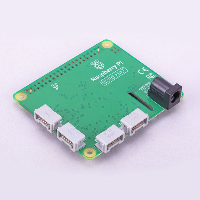
Raspberry Pi Foundation Raspberry Pi Build HAT
Build robust, intelligent machines that combine Raspberry Pi computing power with LEGO components. The Raspberry Pi Build HAT provides four connectors for LEGO Technic motors and sensors from the SPIKE Portfolio. The available sensors include a distance sensor, a color sensor, and a versatile force sensor. The angular motors come in a range of sizes and include integrated encoders that can be queried to find their position. The Build HAT fits all Raspberry Pi computers with a 40-pin GPIO header, including – with the addition of a ribbon cable or other extension device — Raspberry Pi 400. Connected LEGO Technic devices can easily be controlled in Python, alongside standard Raspberry Pi accessories such as a camera module. Features Controls up to 4 motors and sensors Powers the Raspberry Pi (when used with a suitable external PSU) Easy to use from Python on the Raspberry Pi
-
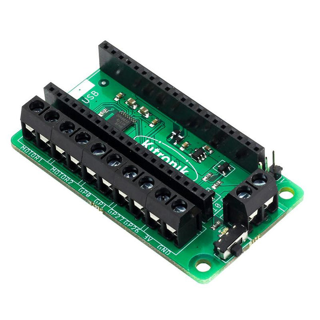
Kitronik Kitronik Motor Driver Board for Raspberry Pi Pico
This board allows the Raspberry Pi Pico (connected via pin header) to drive two motors simultaneously with full forward, reverse & stop control, making it ideal for Pico controlled buggy projects. Alternatively, the board can be used to power a stepper motor. The board features the DRV8833 motor driver IC, which has built-in short circuit, over current and thermal protection. The board has 4 external connections to GPIO pins and a 3 V and GND supply from the Pico. This allows for additional IO options for your buggy builds that can be read or controlled by the Pico. In addition there is an on/off switch and power status LED, allowing you to see at a glance if the board is powered up and save your batteries when your project is not in use. To use the motor driver board, the Pico should have a soldered pin header and be inserted firmly into the connector. The board produces a regulated supply that is fed into the 40-way connector to power the Pico, removing the need to power the Pico directly. The motor driver board is powered via either screw terminals or a servo style connector. Kitronik has developed a micro-python module and sample code to support the use of the Motor Driver board with the Pico. This code is available in the GitHub repo. Features A compact yet feature-packed board designed to sit at the heart of your Raspberry Pi Pico robot buggy projects. The board can drive 2 motors simultaneously with full forward, reverse, and stop control. It features the DRV8833 motor driver IC, which has built-in short circuit, over current and thermal protection. Additionally, the board features an on/off switch and power status LED. Power the board via a terminal block style connector. The 3V and GND pins are also broken out, allowing external devices to be powered. Code it with MicroPython via an editor such as the Thonny editor. Dimensions: 63 mm (L) x 35 mm (W) x 11.6 mm (H) Download Datasheet
-

Elektor Labs Elektor Dual DC LISN (150 kHz – 200 MHz)
Measuring conducted emission is the simplest and most affordable method of getting some indication of whether a design can meet EMI/EMC requirements. A Line Impedance Stabilization Network (LISN) is an indispensable part of an EMC pre-compliance test setup. In cooperation with Würth Elektronik, Elektor has developed a 5 µH, 50 Ω Dual DC LISN that supports voltages up to 60 V and currents up to 10 A. The instrument measures RF interferences on both channels (the power supply) by means of 5-μH blocking inductances. The internal 10-dB attenuation network – one in each channel – contains a 3rd-order high-pass filter with a cutoff frequency of 9 kHz to protect the input of instruments like a spectrum analyzer from potentially harmful DC voltages or low frequencies coming from the EUT (Equipment Under Test). Specifications RF path Channels 2 (with clamping diodes) Bandwidth 150 kHz – 200 MHz Inductance 5 μH || 50 Ω Internal attenuation 10 dB Connectors SMA DC path Max. current < 10 ADC Max. voltage < 60 VDC DC resistance < 2 x 70 mΩ PCB size 94.2 x 57.4 mm Connectors 4-mm banana Hammond enclosure Type 1590N Dimensions 121 x 66 x 40 mm Included 1x 4-layer PCB with all SMT parts fitted 1x pre-drilled enclosure with ready-printed front panel layout 5x gold-plated, insulated, 4-mm banana sockets, rated for 24 A, 1 kV 1x Hammond enclosure 1590N1, Aluminum (Die-Cast Alloy) More Info Project on Elektor Labs: Dual DC LISN for EMC pre-compliance testing Elektor 9-10/2021: EMC Pre-Compliance Test for Your DC-Powered Project (Part 1) Elektor 11-12/2021: EMC Pre-Compliance Test for Your DC-Powered Project (Part 2)
-
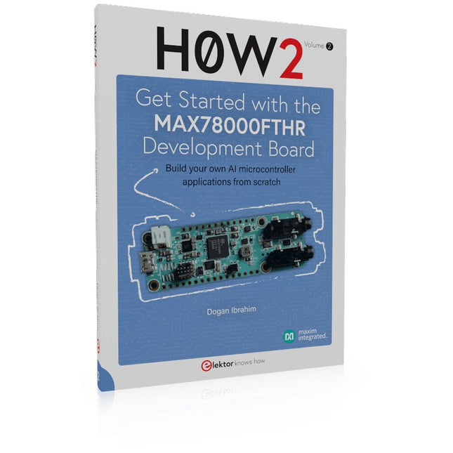
Elektor Publishing H0W2: Get Started with the MAX78000FTHR Development Board
Build your own AI microcontroller applications from scratch The MAX78000FTHR from Maxim Integrated is a small development board based on the MAX78000 MCU. The main usage of this board is in artificial intelligence applications (AI) which generally require large amounts of processing power and memory. It marries an Arm Cortex-M4 processor with a floating-point unit (FPU), convolutional neural network (CNN) accelerator, and RISC-V core into a single device. It is designed for ultra-low power consumption, making it ideal for many portable AI-based applications. This book is project-based and aims to teach the basic features of the MAX78000FTHR. It demonstrates how it can be used in various classical and AI-based projects. Each project is described in detail and complete program listings are provided. Readers should be able to use the projects as they are, or modify them to suit their applications. This book covers the following features of the MAX78000FTHR microcontroller development board: Onboard LEDs and buttons External LEDs and buttons Using analog-to-digital converters I²C projects SPI projects UART projects External interrupts and timer interrupts Using the onboard microphone Using the onboard camera Convolutional Neural Network
€ 39,95
Members: € 35,96
-
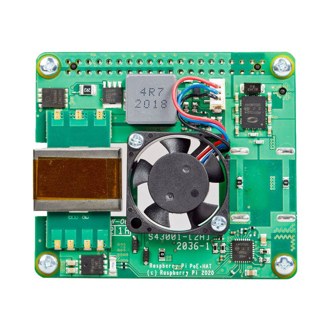
Raspberry Pi Foundation Raspberry Pi PoE+ HAT (for Raspberry Pi 3 B+ and 4)
The Raspberry Pi PoE+ HAT is an add-on board designed for Raspberry Pi 3 B+ and Raspberry Pi 4 equipped with PoE pins. It powers the Raspberry Pi through an Ethernet cable, provided that compatible Power-Sourcing Equipment (PSE) is present on the Ethernet network. Additionally, the HAT includes an integrated fan to cool the Raspberry Pi processor. Specifications Standard IEEE 802.3at-2003 PoE Input voltage 37-57 V DC, Class 4 device Output voltage 5 V DC/4 A Cooling 25 x 25 mm brushless fan delivering 2.2 CFM for processor cooling Operating temperature 0°C to +50°C Downloads Datasheet
-
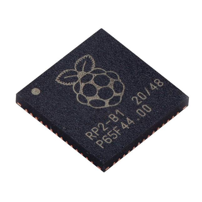
Raspberry Pi Foundation Raspberry Pi RP2040 Microcontroller (10 pcs)
Specifications Dual ARM Cortex-M0+ @ 133 MHz 264 kB on-chip SRAM in six independent banks Support for up to 16 MB of off-chip Flash memory via dedicated QSPI bus DMA controller Fully-connected AHB crossbar Interpolator and integer divider peripherals On-chip programmable LDO to generate core voltage 2x on-chip PLLs to generate USB and core clocks 30x GPIO pins, 4 of which can be used as analogue inputs Peripherals 2x UARTs 2x SPI controllers 2x I²C controllers 16x PWM channels USB 1.1 controller and PHY, with host and device support 8x PIO state machines What you'll get 10x bare RP2040 chips
€ 7,95€ 3,18Best Price
-

Siglent Siglent SDS1104X-U 4-ch Oscilloscope (100 MHz)
The SDS1000X-U series employs SPO (Super Phosphor Oscilloscope) technology that provides excellent signal fidelity and performance. It comes with an innovative digital trigger system with high sensitivity and low jitter, and a waveform capture rate of 400,000 frames/sec (sequence mode). The SDS1000X U also employs a 256 level intensity grading display function and a color temperature display mode not found in other models in this class. Another powerful addition is the new 128 k point FFT math function that gives the SDS1000X-U a very high-frequency resolution when observing signal spectra. SDS1000X-U also supports searching and navigating. The features and performance of SIGLENT’s new SDS1000X-U cannot be matched anywhere else in this price class. Features 100 MHz bandwidth Real-time sampling rate up to 1 GSa/s The newest generation of SPO technology Waveform capture rates up to 100,000 wfm/s (normal mode) and 400,000 wfm/s (sequence mode) Supports 256-level intensity grading and color temperature display modes Record length up to 14 Mpts Digital trigger system Intelligent trigger: Edge, Slope, Pulse Width, Window, Runt, Interval, Time out (Dropout), Pattern Serial bus triggering and decoding (Standard), supports protocols I²C, SPI, UART, CAN, LIN Video trigger, supports HDTV 10 types of one-button shortcuts, supports Auto Setup, Default, Cursors, Measure, Roll, History, Display/Persist, Clear Sweep, Zoom and Print Segmented acquisition (Sequence) mode, divides the maximum record length into multiple segments (up to 80,000), according to trigger conditions set by the user Automatic measurement function for 38 parameters as well as Measurement Statistics, Zoom, Gating, Math, History and Reference functions History waveform record (History) function (maximum recorded waveform length is 80,000 frames) 128 k pts FFT, supports Peaks and Markers Math functions (FFT, addition, subtraction, multiplication, division, integration, differential, square root) Large 7 inch TFT LCD display with 800 x 480 resolution Downloads Datasheet Manual Programming Guide
€ 401,00
-

OWON OWON HDS272S 2-ch Oscilloscope (70 MHz) + Multimeter + Signal Generator
Oscilloscope, multimeter and waveform generator in the same battery-powered device, to work on the go. Features Oscilloscope + multimeter + waveform generator, multifunction in one 3.5-inch high-resolution, high-contrast colour LCD display, suitable for outdoor use 18650 lithium battery, comprehensive power consumption ≤3 W, can work continuously for about 6 hours USB-C interface, support power bank, support PC software connection Self-calibration function SCPI supported, facilitate secondary development Specifications Oscilloscope Bandwidth 70 MHz Channels 2-ch Oscilloscope + 1-ch Generator Sample Rate 250 MSa/s Acquisition Model Normal, Peak detect Record Length 8K Display 3.5-inch LCD Waveform Refresh Rate 10,000 wfrms/s Input Coupling DC, AC, and Ground Input Impedance 1 MΩ ±2%, in parallel with 16pF±10pF Probe Attenuation Factors 1X,10X,100X,1000X,10000X Max. input Voltage 400 V (DC+AC, PK-PK, 1MΩ input impedance) (10:1 probe attenuation) Bandwidth Limit (typical) 20 MHz Horizontal Scale 5 ns/div - 1000 s/div, step by 1 - 2 - 5 Vertical Sensitivity 10 mV/div - 10 V/div Vertical Resolution 8 bits Trigger Type Edge Trigger Modes Auto, Normal, single Automatic Measurement Period, Frequency, Mean, PK-PK, Max, Min Cursor Measurement ΔV, ΔT, ΔT& ΔV between cursors Communication Interface USB Type-C Multimeter Max. Resolution 20,000 counts Testing Mode Voltage, Current, Resistance, Capacitance, Diode, and Continuity test Input Impedance 10 MΩ Max Input Voltage AC: 750 V | DC: 1000 V Max Input Current DC: 10 A | AC: 10 A Diode 0-2 V Waveform Generator Frequency Output Sine 0.1 Hz - 25 MHz Square 0.1 Hz - 5 MHz Ramp 0.1 Hz - 1 MHz Pulse 0.1 Hz - 5 MHz Arbitrary 0.1 Hz - 5 MHz Sampling Rate 125 MSa/s Channel 1-ch Amplitude Range 20 mVpp - 5 Vpp Waveform Length 8K Vertical Resolution 14 bits Output Impedance 50Ω Downloads User Manual for HDS200 Series SCPI Protocol for HDS200 Series Quick Guide for HDS200 Series PC Software for OWON HDS200 Series
€ 199,65
-

OWON OWON XDM1041 True RMS Multimeter
The OWON XDM1041 is a fast, high-precision digital True RMS benchtop multimeter with a high-resolution 3.5-inch LCD and 50,000 counts. Its DC voltage accuracy is up to 0.05% and it can measure up to 65 values per second. Features 3.5“ high-resolution LCD (480x320 pixels) 55000 counts, DC voltage accuracy up to 0.05% Up to 65 readings per second Dual line display supported Trend analysis accessible in chart mode AC True RMS measurements (bandwidth: 20 Hz – 1 kHz) SCPI support: Remote control the multimeter through PC software via USB port Data record function, you can record the measured data into internal memory, and then read and process the recorded data with your computer. Specifications Measurement Range Resolution Accuracy DC Voltage 50.000 mV 0.001 mV 0.1% +10 500.00 mV 0.01 mV 0.05% +5 5.0000 V 0.0001 V 0.05% +5 50.000 V 0.001 V 0.05% +5 500.00 V 0.01 V 0.1% +5 1000.0 V 0.1 V 0.1% +10 AC Voltage 500 mV~750 V 20 Hz~45 Hz 1% +30 45 Hz~65 Hz 0.5% +30 65 Hz~1 KHz 0.7% +30 DC Current 500 uA 0.01 uA 0.15% +20 5000 uA 0.1 uA 0.15% +10 50 mA 0.001 mA 0.15% +20 500 mA 0.01 mA 0.15% +10 5 A 0.0001 A 0.5% +10 10 A 0.001 A 0.5% +10 AC Current 500 uA~500 mA 20 Hz~1 KHz 0.5% +20 5 A-10 A 1.5% +20 Resistance 500 Ω 0.01 Ω 0.15% +10 5 KΩ 0.0001 KΩ 0.15% +5 50 KΩ 0.001 KΩ 0.15% +5 500 KΩ 0.01 KΩ 0.15% +5 5 MΩ 0.0001 MΩ 0.3% +5 50 MΩ 0.001 MΩ 1% +10 Frequency 10.000 Hz~60 MHz / ±(0.2% +10) Capacitance 50 nF~500 uF / 2.5% +10 5 mF~50 mF 5% +10 Diode 3.0000 V 0.0001 V / Continuity 1000 Ω 0.1 Ω Adjustable threshold Temperature K type, PT100 Max Display 55,000 counts Data-logging Function Logging Duration 15ms~9999.999s Logging Length 1,000 points Display 3.5“ TFT LCD (480x320 pixels) Power supply 230 V AC mains voltage Dimensions 200 x 88 x 150 mm Weight approx. 0.5 kg Included 1x OWON XDM1041 Multimeter 1x Power cord 2x Test leads 1x Fuse 1x USB cable 1x Manual Downloads Programming Manual PC Software
€ 94,38
-
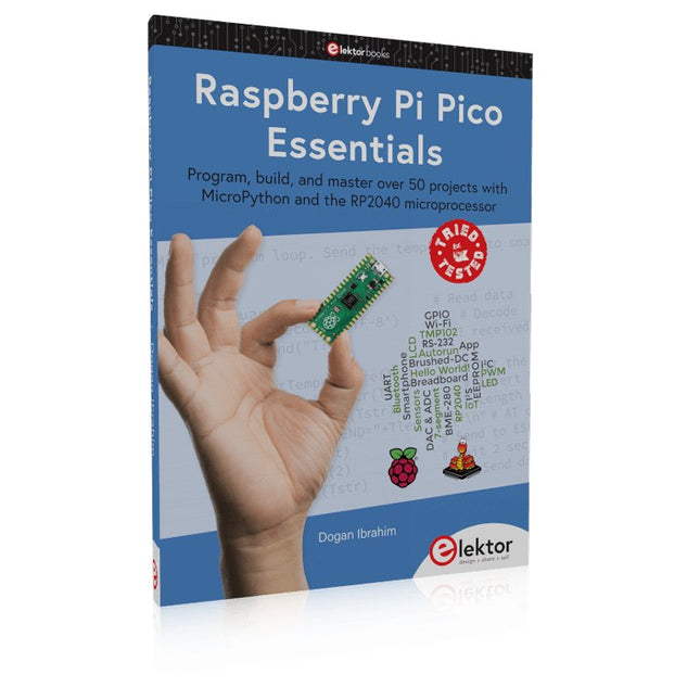
Elektor Publishing Raspberry Pi Pico Essentials
Program, build, and master over 50 projects with MicroPython and the RP2040 microprocessor The Raspberry Pi Pico is a high-performance microcontroller module designed especially for physical computing. Microcontrollers differ from single-board computers, like the Raspberry Pi 4, in not having an operating system. The Raspberry Pi Pico can be programmed to run a single task very efficiently within real-time control and monitoring applications requiring speed. The ‘Pico’ as we call it, is based on the fast, efficient, and low-cost dual-core ARM Cortex-M0+ RP2040 microcontroller chip running at up to 133 MHz and sporting 264 KB of SRAM, and 2 MB of Flash memory. Besides its large memory, the Pico has even more attractive features including a vast number of GPIO pins, and popular interface modules like ADC, SPI, I²C, UART, and PWM. To cap it all, the chip offers fast and accurate timing modules, a hardware debug interface, and an internal temperature sensor. The Raspberry Pi Pico is easily programmed using popular high-level languages such as MicroPython and or C/C++. This book is an introduction to using the Raspberry Pi Pico microcontroller in conjunction with the MicroPython programming language. The Thonny development environment (IDE) is used in all the projects described. There are over 50 working and tested projects in the book, covering the following topics: Installing the MicroPython on Raspberry Pi Pico using a Raspberry Pi or a PC Timer interrupts and external interrupts Analogue-to-digital converter (ADC) projects Using the internal temperature sensor and external temperature sensor chips Datalogging projects PWM, UART, I²C, and SPI projects Using Wi-Fi and apps to communicate with smartphones Using Bluetooth and apps to communicate with smartphones Digital-to-analogue converter (DAC) projects All projects given in the book have been fully tested and are working. Only basic programming and electronics experience is required to follow the projects. Brief descriptions, block diagrams, detailed circuit diagrams, and full MicroPython program listings are given for all projects described. Readers can find the program listings on the Elektor web page created to support the book.
€ 39,95
Members: € 35,96
-
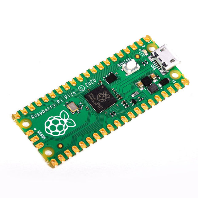
Raspberry Pi Foundation Raspberry Pi Pico
Specifications RP2040 microcontroller chip designed by Raspberry Pi in the UK Dual-core ARM Cortex M0+ processor, with a flexible clock running up to 133 MHz 264 kB SRAM, and 2 MB on-board Flash memory Castellated module allows soldering directly to carrier boards USB 1.1 host and device support Energy-efficient sleep and dormant modes Drag and drop programming using mass storage via USB 26x multifunction GPIO pins 2x SPI, 2x I²C, 2x UART, 3x 12-bit ADC, 16x controllable PWM channels On-chip accurate clock and timer Temperature sensor On-chip accelerated floating point libraries 8x programmable IO (PIO) state machines for custom peripherals Why a Raspberry Pi Pico? Designing your own microcontroller instead of buying an existing one brings a number of advantages. According to Raspberry Pi itself, not one of the existing products available for this comes close to their price/performance ratio. This Raspberry Pi Pico has also given Raspberry Pi the ability to add some innovative and powerful features of their own. These features are not available anywhere else. A third reason is that the Raspberry Pi Pico has given Raspberry Pi the ability to create powerful software around the product. Surrounding this software stack is an extensive documentation set. The software and documentation meet the high standard of Raspberry Pi's core products (such as the Raspberry Pi 400, Pi 4 Model B and Pi 3 Model A+). Who is this microcontroller for? The Raspberry Pi Pico is suitable for both advanced and novice users. From controlling a display to controlling many different devices that you use every day. Automating everyday operations is made possible by this technology. Beginner users The Raspberry Pi Pico is programmable in the C and MicroPython languages and is customizable for a wide range of devices. In addition, the Pico is as easy to use as dragging and dropping files. This makes this microcontroller ideally suited for the novice user. Advanced users For advanced users, it is possible to take advantage of the Pico's extensive peripherals. The peripherals include the SPI, I²C, and eight programmable I/O (PIO)-state machines. What makes the Raspberry Pi Pico unique? What's unique about the Pico is that it was developed by Raspberry Pi itself. The RP2040 features a dual-core Arm Cortex-M0+ processor with 264 KB of internal RAM and support for up to 16 MB of off-chip Flash. The Raspberry Pi Pico is unique for several reasons: The product has the highest price/quality ratio in the microcontroller board market. The Raspberry Pi Pico has been developed by Raspberry Pi itself. The software stack surrounding this product is of high quality and comes paired with a comprehensive documentation set.
-
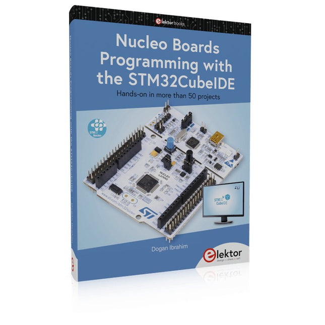
Elektor Publishing Nucleo Boards Programming with the STM32CubeIDE
Hands-on in more than 50 projects STM32 Nucleo family of processors are manufactured by STMicroelectronics. These are low-cost ARM microcontroller development boards. This book is about developing projects using the popular STM32CubeIDE software with the Nucleo-L476RG development board. In the early Chapters of the book the architecture of the Nucleo family is briefly described. The book covers many projects using most features of the Nucleo-L476RG development board where the full software listings for the STM32CubeIDE are given for each project together with extensive descriptions. The projects range from simple flashing LEDs to more complex projects using modules, devices, and libraries such as GPIO, ADC, DAC, I²C, SPI, LCD, DMA, analogue inputs, power management, X-CUBE-MEMS1 library, DEBUGGING, and others. In addition, several projects are given using the popular Nucleo Expansion Boards. These Expansion Boards plug on top of the Nucleo development boards and provide sensors, relays, accelerometers, gyroscopes, Wi-Fi, and many others. Using an expansion board together with the X-CUBE-MEMS1 library simplifies the task of project development considerably. All the projects in the book have been tested and are working. The following sub-headings are given for each project: Project Title, Description, Aim, Block Diagram, Circuit Diagram, and Program Listing for the STM32CubeIDE. In this book you will learn about STM32 microcontroller architecture; the Nucleo-L476RG development board in projects using the STM32CubeIDE integrated software development tool; external and internal interrupts and DMA; DEBUG, a program developed using the STM32CubeIDE; the MCU in Sleep, Stop, and in Standby modes; Nucleo Expansion Boards with the Nucleo development boards. What you need a PC with Internet connection and a USB port; STM32CubeIDE software (available at STMicroelectronics website free of charge) the project source files, available from the book’s webpage hosted by Elektor; Nucleo-L476RG development board; simple electronic devices such as LEDs, temperature sensor, I²C and SPI chips, and a few more; Nucleo Expansion Boards (optional).
€ 49,95
Members: € 44,96
-

OWON OWON SDS1104 4-ch Oscilloscope (100 MHz)
The OWON SDS1104 oscilloscope is a practical choice for engineers, technicians, students, and hobbyists who need accurate signal analysis without the cost of high-end instruments. With its 100 MHz bandwidth and 1 GSa/s sampling rate, it reliably captures low- to mid-frequency signals, making it well suited for electronics development, troubleshooting, and educational use. Equipped with a 7-inch color TFT display, the SDS1104 provides clear waveform visualization, while automatic measurement functions and FFT analysis help users quickly evaluate frequency, voltage, and timing parameters. Advanced math operations, cursor measurements, and multiple trigger modes add further flexibility, making the oscilloscope a versatile tool for a wide range of testing scenarios. Specifications Bandwidth 100 MHz Sample Rate 1 GS/s Horizontal Scale (s/div) 5ns/div - 1000s/div, step by 1 - 2 - 5 Channel 4 Display 7" color LCD, 800 x 480 pixels Input Coupling DC, AC and GND Vertical Resolution (A/D) Vertical Resolution (A/D) Vertical Sensitivity 5mV/div - 5V/div (at input) Trigger Type Edge, Video Trigger Mode Auto, Normal and Single Waveform Math +, -, x, ÷, invert, FFT Fuse 2A, T class, 250 V Dimension (W x H x D) 301 x 152 x 70 mm Weight 1.1 kg Included 1x OWON SDS1104 Oscilloscope 1x Mains power cord 1x CD Rom 1x Quickstart Guide 1x USB Cable 4x Oscilloscope probe 1x Probe Adjust Downloads Datasheet Manual
€ 249,00
-
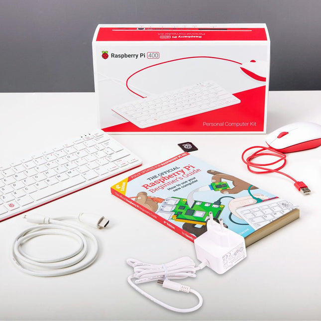
Raspberry Pi Foundation Raspberry Pi 400 Kit (EU)
The Raspberry Pi 400 offers a quad-core 64-bit processor, 4 GB RAM, wireless networking, dual-display output, 4K video playback, and a 40-pin GPIO header. It's a powerful, compact computer built into a portable keyboard. Specifications (Raspberry Pi 400) Processor Broadcom BCM2711 quad-core Cortex-A72 (ARM v8) 64-bit SoC @ 1.8 GHz RAM 4 GB LPDDR4-3200 Connectivity Dual-band (2.4 GHz and 5.0 GHz) IEEE 802.11b/g/n/ac wireless LANBluetooth 5.0, BLEGigabit Ethernet2 × USB 3.0 and 1 × USB 2.0 ports GPIO Horizontal 40-pin GPIO header Video & Sound 2 × micro HDMI ports (supports up to 4Kp60) Multimedia H.265 (4Kp60 decode)H.264 (1080p60 decode, 1080p30 encode)OpenGL ES 3.0 graphics SD card support MicroSD card slot for operating system and data storage Keyboard US keyboard Power 5 V DC via USB connector Operating temperature 0°C to +40°C Dimensions 286 × 122 × 23 mm (maximum) Included Raspberry Pi 400 (US keyboard layout, QWERTY) Official EU Power Supply (5.1 V, 3 A) for Raspberry Pi 4 (white) Official Raspberry Pi Mouse (white/red) Official HDMI Cable for Raspberry Pi 4 (white, 1 m) microSD Card (16 GB, Class 10) with SD Adapter (Pre-Installed with NOOBS) The Official Raspberry Pi Beginner's Guide (4th Edition)
-
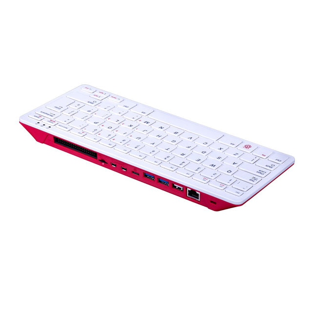
Raspberry Pi Foundation Raspberry Pi 400 (US)
The Raspberry Pi 400 offers a quad-core 64-bit processor, 4 GB RAM, wireless networking, dual-display output, 4K video playback, and a 40-pin GPIO header. It's a powerful, compact computer built into a portable keyboard. Specifications Processor Broadcom BCM2711 quad-core Cortex-A72 (ARM v8) 64-bit SoC @ 1.8 GHz RAM 4 GB LPDDR4-3200 Connectivity Dual-band (2.4 GHz and 5.0 GHz) IEEE 802.11b/g/n/ac wireless LANBluetooth 5.0, BLEGigabit Ethernet2x USB 3.0 and 1x USB 2.0 ports GPIO Horizontal 40-pin GPIO header Video & Sound 2 × micro HDMI ports (supports up to 4Kp60) Multimedia H.265 (4Kp60 decode)H.264 (1080p60 decode, 1080p30 encode)OpenGL ES 3.0 graphics SD card support MicroSD card slot for operating system and data storage Keyboard US keyboard Power 5 V DC via USB connector Operating temperature 0°C to +40°C Dimensions 286 x 122 x 23 mm (maximum)
-
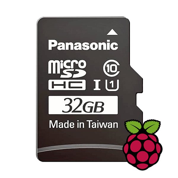
Raspberry Pi Foundation microSD Card pre-installed with Raspberry Pi OS (32 GB)
With this microSD (32 GB) with pre-installed Raspberry Pi OS you can start using your Raspberry Pi right away. Just plug it in and get started!
-

Siglent Siglent SDS1104X-E 4-ch Oscilloscope (100 MHz)
The Siglent SDS1104X-E employs a new generation of SPO (Super Phosphor Oscilloscope) technology that provides excellent signal fidelity and performance. The system noise is also lower than similar products in the industry. It comes with a minimum vertical input range of 500 uV/div, an innovative digital trigger system with high sensitivity and low jitter, and a waveform capture rate of 400,000 frames/sec (sequence mode). The SDS1104X-E also employs a 256-level intensity grading display function and a color temperature display mode not found in other models in this class. SIGLENT’s latest oscilloscopes offering supports multiple powerful triggering modes including serial bus triggering. Serial decoding is free and includes IIC, SPI, UART, CAN, and LIN. History waveform recording and sequential triggering enable extended waveform recording and analysis. Another powerful addition is the new 1 Mpt FFT math function that gives the SDS1104X-E very high frequency resolution when observing signal spectra. Features Intelligent trigger: Edge, Slope, Pulse Width, Window, Runt, Interval, Timeout (Dropout), and Pattern Free Serial bus triggering and decoding:IIC, SPI, UART, RS232, CAN, and LIN Video triggers and supports HDTV Low background noise and 500 μV / div to 10 V / div voltage scales 10 types of one-button shortcuts, supports Auto Setup, Default, Cursors, Measure, Roll, History, Display/Persist, Clear Sweep, Zoom and Print Segmented acquisition (Sequence) mode, dividing the maximum record length into multiple segments (up to 80,000), according to trigger conditions set by the user, with a very small dead time segment to capture the qualifying event. History waveform record (History) function, the maximum recorded waveform length is 80,000 frames Automatic measurement function on 38 parameters, supports Statistics, Gating measurement, Math measurement, History measurement and Ref measurement 1 Mpts FFT True measurement and math can use all 14 Mpts of memory Preset key can be customized for user settings or factory “defaults” Security Erase mode Highspeed hardware based Pass/ Fail function Large 7-inch TFT-LCD display with 800 * 480 resolution Multiple interface types: USB Host, USB Device (USB-TMC), LAN (VXI-11), Pass / Fail, Trigger Out Supports SCPI remote control commands Multi-language display and embedded help Browser control/onboard webpage for software free monitoring (4 channel models only) Included 1x Siglent SDS1104X-E Oscilloscope 4x 100 MHz probes 1x Guarantee Card 1x Power Cord 1x USB Cable 1x Quick Start Guide Downloads Datasheet Manual Programming Guide
€ 508,71
-
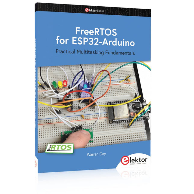
Elektor Publishing FreeRTOS for ESP32-Arduino
Practical Multitasking Fundamentals Programming embedded systems is difficult because of resource constraints and limited debugging facilities. Why develop your own Real-Time Operating System (RTOS) as well as your application when the proven FreeRTOS software is freely available? Why not start with a validated foundation? Every software developer knows that you must divide a difficult problem into smaller ones to conquer it. Using separate preemptive tasks and FreeRTOS communication mechanisms, a clean separation of functions is achieved within the entire application. This results in safe and maintainable designs. Practicing engineers and students alike can use this book and the ESP32 Arduino environment to wade into FreeRTOS concepts at a comfortable pace. The well-organized text enables you to master each concept before starting the next chapter. Practical breadboard experiments and schematics are included to bring the lessons home. Experience is the best teacher. Each chapter includes exercises to test your knowledge. The coverage of the FreeRTOS Application Programming Interface (API) is complete for the ESP32 Arduino environment. You can apply what you learn to other FreeRTOS environments, including Espressif’s ESP-IDF. The source code is available from GitHub. All of these resources put you in the driver’s seat when it is time to develop your next uber-cool ESP32 project. What you will learn: How preemptive scheduling works within FreeRTOS The Arduino startup “loopTask” Message queues FreeRTOS timers and the IDLE task The semaphore, mutex, and their differences The mailbox and its application Real-time task priorities and its effect Interrupt interaction and use with FreeRTOS Queue sets Notifying tasks with events Event groups Critical sections Task local storage The gatekeeper task
€ 49,95
Members: € 44,96


