This bundle includes the Red Pitaya STEMlab 125-14 PRO Gen 2 Starter Kit and the new book "Experimenting with Red Pitaya STEMlab Gen 2".
The Red Pitaya STEMlab 125-14 PRO Gen 2 Starter Kit is a powerful and flexible platform for signal processing, data acquisition, and electronic measurement applications. Designed for engineers, developers, researchers, and educators, this kit provides everything required to start building advanced measurement and control systems.
At the core of the kit is the STEMlab 125-14 PRO Gen 2 board, an upgraded and ultra-lightweight development platform. Powered by the Xilinx Zynq-7010 SoC with 512 MB of RAM, it combines FPGA programmability with ARM processing power to enable high-performance instrumentation and custom signal-processing solutions.
The board offers 14-bit ADC and DAC resolution, a 125 MS/s sampling rate, an input range of ±20 V, and up to 60 MHz bandwidth. Its improved low-noise analog front-end, USB-C connectivity, and compact design make it suitable for demanding applications such as RF development, radar systems, photonics research, software-defined radio (SDR), and industrial automation.
The Starter Kit includes all essential accessories for immediate use: a microSD card with preinstalled operating system, power supply, Ethernet cable for remote access, two 100 MHz oscilloscope probes, and SMA-to-BNC adapters for flexible signal connections.
The Red Pitaya STEMlab 125-14 PRO Gen 2 Starter Kit is an excellent platform for rapid prototyping, FPGA development, measurement instrumentation, and advanced electronics experimentation.
Features
14-bit ADC and DAC resolution
125 MS/s sampling rate
±20 V input range
Up to 60 MHz bandwidth
Xilinx Zynq-7010 SoC (FPGA + ARM processor)
512 MB RAM
Low-noise analog front- and back-ends
Applications
RF development and testing
Radar and wireless systems
Software-defined radio (SDR)
Photonics and optical research
Industrial automation and control systems
Signal analysis and instrumentation
Rapid prototyping of electronic measurement systems
Specifications
Processor
Dual-core ARM Cortex-A9
FPGA
AMD Xilinx Zynq-7010 SoC
RAM
512 MB (4 Gb)
Storage
microSD card (up to 32 GB)
Operating System
Linux-based Red Pitaya OS
ADC Resolution
14-bit
DAC Resolution
14-bit
Bandwidth
60 MHz (DC)
Sampling Rate
125 MS/s
Analog Input Channels
2
Analog Output Channels
2
Input Voltage Range
±1 V (LV) / ±20 V (HV)
Input Impedance
1 MΩ / 10 pF
Output Voltage Range
±1 V
Ethernet
1x Gigabit Ethernet (RJ45)
USB
2x USB-C 2.0 (for power and console)
Digital I/O
16x GPIO (3.3 V)
Communication Interfaces
I²C, SPI, UART, CAN
Power Supply
5 V/3 A via USB-C
Dimensions
106.8 x 60.0 x 17.9 mm
Included
1x Red Pitaya STEMlab 125-14 PRO Gen 2 board
2x 100 MHz oscilloscope probes
2x SMA-to-BNC adapters
1x microSD card with preinstalled OS
1x USB-C Power supply
1x Ethernet cable
Downloads
Documentation
Schematics
Book: Experimenting with Red Pitaya STEMlab Gen 2
With this new book, Red Pitaya goes beyond a versatile board. It becomes a powerful laboratory instrument for precision measurement, analysis, and control.
From the fundamentals of electronic project development, monitoring, control, and design to testing, this book walks you step-by-step through everything you need to know to harness the full potential of Red Pitaya hardware and software.
The book presents real-time, FPGA-based projects that are developed on a PC using the Vivado environment, then transferred to the Red Pitaya for execution and testing.
You will learn about enhanced performance, expanded I/O capabilities, improved FPGA features, and advanced connectivity options that open up new frontiers for precision measurement, monitoring, and control in your embedded applications.
Inside the book you will discover:
A deep dive into Red Pitaya architecture and hardware design
Electronic experiments using Red Pitaya for measurement and monitoring
Hands-on projects using the Python programming language
Practical guidance for FPGA programming using Red Pitaya
Red Pitaya FPGA projects using the Verilog HDL under Vivado IDE
Practical design of electronic projects including measurement and testing
Step-by-step examples that bridge theory and real-world implementation
Whether you are designing your own electronic circuits, developing signal analysis tools, or creating real-time control or monitoring systems, this book provides you the knowledge and confidence you need to fully learn and customize the Red Pitaya platform.
The Elektor Zener Diode Tester is essentially a constant-current source that can be switched in steps from 1 to 50 mA. It can be used to test Z-diodes up to a maximum of 54 V. Thanks to a 60-V step-up converter, the device can be powered by the usual 5 to 12 V.
The principle of this tester is straightforward. A Z-diode or other DUT (device under test, such as an LED) is biased by an adjustable current source. The voltage across the DUT can be measured with a multimeter. The voltage of most (small) Z-diodes is specified at a current of 5 mA. Depending on the application, the voltage at other currents can also be of interest. That is why six current settings are available: 1, 2, 5, 10, 20, and 50 mA. LEDs are often specified at a current of 20 mA.
What can be tested is:
Whether a Z-diode is defective (short circuit or high impedance).
Whether a Z-diode exhibits the correct Z-voltage.
How a Z-voltage changes with different currents.
What exact voltage is present at an integrated voltage reference.
Whether LEDs in a series chain differ in brightness (hence the 20 mA current).
What the current gain is for different base currents in (power) transistors.
The kit contains all parts listed in the bill of materials including PCB and enclosure.
Specifications
Supply voltage
5…12 V/2 A (USB-C)
Supply current (Itest = 50 mA)
1.1 A @ 5 V / 412 mA @ 12 V
Selectable currents
1, 2, 5, 10, 20, and 50 mA
Max. test voltage
>54 V @ Itest ≥1 mA
Max. output voltage
60 V @ Itest = 0 mA
Voltage limit at 5 V
4.5 V @ Itest = 1 mA / 5.18 V @ Itest = 50 mA
Enclosure dimensions
110 x 82 x 44 mm
PCB size
105.4 x 67.3 mm
Connections
4 mm banana sockets for multimeter
2 mm banana sockets for test clips
USB-C socket for power supply
Included
Resistors
R1 = 3.3 kΩ, 600 mW, 1%
R2 = 0.15 Ω, 1 W, 5%, LS 12.7 mm, ø 3.5 mm
R3, R8 = 180 Ω, 600 mW, 1%
R4, R6, R16 = 1 kΩ, 600 mW, 1%
R5, R19 = 47 kΩ, 600 mW, 1%
R7 = 3.9 kΩ, 1 W, 5%, LS 12.7 mm, ø 3.5 mm
R9, R10, R12 = 10 kΩ, 600 mW, 1%
R11, R13 = 100 Ω, 600 mW 1%
R14 = 249 Ω, 600 mW, 1%
R15 = 499 Ω, 600 mW, 1%
R17 = 2.49 kΩ, 250 mW, 1%
R18 = 4.99 kΩ, 250 mW, 1%
Capacitors
C1 = 470 uF / 35 V, 20%, Ir = 1.86 A, ø 12.5 mm, LS 5 mm, ESR = 0.038 Ω (Panasonic EEUTP1V471)
C2 = 1 uF / 100 V, 10%, X7R, LS 5 mm
C3 = 2.2 nF / 50 V, 10%, X7R, LS 5 mm
C4, C7 = 100 nF / 100 V, 10%, X7R, LS 5 mm
C5 = 100 uF / 100 V, 20%, ø 14 mm max., LS 5 mm
C6 = 1 nF / 100 V, 10%, X7R, LS 5 mm
Inductor
L1 = 100 uH, Irms = 2.4 A, Isat = 3.5 A, 0.09 Ω, radial, pitch 2.5/5/10 mm, ø 14 mm max. (Kemet SBC8-101-242)
Semiconductors
D1 = MUR120G, DO-41
D2, D4 = STPS3150RL, DO-201AD
D3 = Z-diode, 18 V, 1.3 W (BZX85C18)
D5 = Z-diode, 5.1 V, 0.5 W (1N5231B)
LED1 = LED in pushbutton S1
LED2 = LED, green, 3 mm
IC1 = MC34063, DIP-8
IC2 = LM4040BIZ-5.0/NOPB, TO-92 (TO-226AA-3)
IC3 = TL051CP, DIP-8
T1 = BC327.25, TO-92
T2 = STP40NF10L, TO-220
T3 = IRF9510PBF, TO-220
T4 = 2N7000, TO-92
Others
K1, K2, S1, S3 = 2-way screw terminal block, LS 3.5 mm, max. 1.5 mm²
connected to K1 = USB-C socket, 30 V/3 A, chassis mounted, wired, 9 x 16 mm
connected to K2 = Banana Connector, 2 mm, Socket, 60 VDC, Panel Mount, red (Multicomp 24.102.1)
connected to K2 = Banana Connector, 2 mm, Socket, 60 VDC, Panel Mount, black (Multicomp 24.102.2)
Test clip, red, 30 VAC/60 VDC (Hirschmann 931467101)
Test clip, black, 30 VAC/60 VDC (Hirschmann 931467100)
S1 = Pushbutton, panel mount, SPST-NO, 30 DC/100 mA, with red LED
S2 = Rotary Switch, 6 position, 2 pole, 30°, 250 V/150 mA
S3 = Toggle switch, panel mount, SPDT, solder lugs, 28 VDC
T2, T3 = Heat sink, 15°C/W, FK 214 SA-CB
Enclosure Hammond 1591XXSSBK, ABS, 110 x 82 x 44 mm
Knob for S2, round shaft 6 mm, ø 21 mm, with indicator line (Multicomp CP-LB21-6-6D)
4 x Self-tapping screw #4-1/4", carbon steel, pan head
Banana plug, red, 2 mm, 60 VDC (Multicomp 25.205.1)
Banana plug, black, 2 mm, 60 VDC (Multicomp 25.205.2)
Banana socket, black 4 mm, panel mount
Banana socket, red 4 mm, panel mount
for LED1, LED2 = Pin header, 1 x 2, vertical, pitch 2.54 mm
for LED1, LED2 = Pin socket, 1 x 2, vertical, pitch 2.54 mm
for T2, T3 = M3 screw, 10 mm, steel, pan head
2 x M3 washer, plain, steel
4 x M3 nut
for IC1, IC3 = DIP-8 socket
Wire, black, 0.25 mm² (24 AWG), stranded 14 x 0.15 mm, 1 m
Wire, red, 0.25 mm² (24 AWG), stranded 14 x 0.15 mm, 1 m
PCB 250772-1 v1.1
Links
Article
Elektor Labs
AI in Practice
Dive into the fascinating world of robotics and automation!
This Elektor Special shows you how to build your own robots with creativity, a little know-how, and affordable technology. From your first DIY project with Arduino or Raspberry Pi to intelligent systems with AI – this issue makes modern robotics understandable and accessible.
Discover practical instructions, inspiring projects, and exciting insights into the maker scene. Learn how experimentation, community, and openness give rise to true innovation – and why robotics is so much more than just a technical hobby.
Contents
Imagination turns into reality
Arduino-controlled Drawing Robot
GalaxyRVR Mars Rover Kit for Arduino
YDLIDAR X4Pro Lidar
xHuskyLens AI Camera
DOF Robot Arm with Raspberry Pi Pico
Manufacturing Robots with Fischertechnik
Pneumatic Industrial Robot
Why Do We Keep Building Robot Dogs?
Elektor Mini-Wheelie
Robot Vehicles and Autonomous Driving
Elektor GREEN and GOLD members can download their digital edition here.
Not a member yet? Click here.
PIO Programming on the Raspberry Pi PicoNine Instructions, Many Possibilities
Breaking AI Out of the BrowserUsing AI CLIs to Code, Compile, and Validate Embedded Projects
The Scrutiny DebuggerDebug, Visualize, and Test Embedded C/C++ Code
Sigfox Breakout Board (1)A Self-Built Radio BoB
Low-Noise Power Supply (2)Construction, Assembly, and Practical Implementation
Simple Signal Generator Using the RP2040Analog and Digital Signals for Around €10
Navigating the Future of Smart Homes with Matter and Edge AIAre Matter’s Latest Updates and the Rise of Edge AI Finally Giving Engineers the Tools to Build the Intelligent, Seamless Smart Homes Users Have Been Promised?
Differential Pressure SensorsPredictive Maintenance in HVAC-Systems
Security by DesignEngineering Fundamentals Limit Failure
Embedded Security Is No Longer Optional
CRA and PQC Are Rewriting Embedded Security PrioritiesWhy Even Small IoT and Industrial Firms Need an Upgrade Plan
embedded world 2026An Interview With Benedikt Weyerer, Executive Director of embedded world
Hands on with I3CUsing Hardware from ST and Microchip
The BLEnky ProjectRapid Prototyping of Bluetooth Low Energy Applications
Pulse Width ModulationFrom a Simple On/Off Thermostat to a Smoothed DC Analog Signal
AudiotronicsEar-Pleasing Electronics for DIY Construction
From Life’s ExperienceRead The F...ing Manual!
ESP32 Audio Transceiver Board (Part 4)Tuning the Clocks - And a Wired Option
2026: An AI OdysseyThe 2025 Vibe-Coding Hangover
Symmetrical DC LoadDC Load, Static or Dynamic, and Symmetrical
Counting Faces with MaixCAMAn Easy Way to Capture Audience Sizes
Learn to Build Intelligent Embedded Systems
Build smarter embedded systems with Arduino UNO Q. This book gives you the tools, knowledge, and confidence to turn ideas into intelligent, working solutions using the Arduino UNO Q platform. Discover how to build intelligent embedded systems with the Arduino UNO Q and AI.
Unlock the full potential of the Arduino UNO Q, a next-generation platform that combines the real-time power of the STM32U585 microcontroller with the flexibility of a Qualcomm Dragonwing QRB2210 microprocessor.
Learn how to rapidly prototype real-world applications using the Arduino IDE for low-level embedded control and Python in Arduino App Lab for high-level development.
Build confidence through hands-on projects that guide you step by step from basic board features to complete working systems.
Explore ready-to-use, AI based Arduino App Lab examples and see how they can jump-start your development and reduce time to deployment.
Step into the world of Edge AI with a clear, practical introduction to Edge Impulse Studio—no prior AI experience required.
Follow a complete, real-world workflow to create a Keyword Spotting AI application, covering data collection, model training, optimization, and on-device inference using the Edge Impulse Studio.
Bridge the gap between embedded systems and machine learning and learn how to bring intelligence directly onto your hardware.
Perfect for embedded engineers, educators, students, and makers looking to stay ahead in AI-enabled product development.
More than 275 Power Supply Designs for Home Construction
This USB Stick contains over 275 different power supply circuits from the volumes 2001-2025 of Elektor. The article search feature allows you to search full-text content. The results are always displayed as pre-formatted PDF documents.
Highlights
Cuk Converter
Automatic Battery Switchover
Battery Voltage LED
Digital Benchtop Power Supply
Lithium-Ion Charger
Solar Cell Charger
Electronic Fuse
High Voltage Regulator
Power Supply for USB Devices
Step-up Converter for LEDs
Battery Management
and much more...
On the Stick you will also find a folder with additional material such as PCB layouts, Gerber files and software.
Specifications
Storage
16 GB
Interfaces
1x USB-A1x USB-C
System requirements
PC with Adobe Reader 7.0 or higher
Web browser
The ZD-8962B soldering station features an adjustable temperature range of 160°C to 480°C with an output power of 70 W. Equipped with an integrated heating element in the soldering tip, the station reaches the desired operating temperature in just 8 seconds.
A large digital display provides real-time monitoring, showing both the preset target and the actual temperature of the iron for precision control. Additionally, the station is ESD-safe, ensuring sensitive electronic components are fully protected from electrostatic discharge during use.
Specifications
Power
70 W
Input voltage
220-240 V AC/50 Hz
Output voltage
20 V
Temperature range
160°C – 480°C (320°F – 896°F)
Heating time
~8 s
Display
Large, two-line LED display for showing target and actual temperature
Special features
ESD protection, Sleep mode/energy-saving function, Switch between °C and °F
Included
ZD-8962B Soldering station unit
Soldering iron
Soldering tip N12-1
Soldering iron stand with copper brush and sponge
Soldering wire stand with lead-free soldering wire (10 g)
Power cable (EU)
Manual
Practical Projects and Programs
With Experimenting with Red Pitaya STEMlab Gen 2, Red Pitaya goes beyond a versatile board. It becomes a powerful laboratory instrument for precision measurement, analysis, and control.
From the fundamentals of electronic project development, monitoring, control, and design to testing, this book walks you step-by-step through everything you need to know to harness the full potential of Red Pitaya hardware and software.
The book presents real-time, FPGA-based projects that are developed on a PC using the Vivado environment, then transferred to the Red Pitaya for execution and testing.
You will learn about enhanced performance, expanded I/O capabilities, improved FPGA features, and advanced connectivity options that open up new frontiers for precision measurement, monitoring, and control in your embedded applications.
Inside the book you will discover:
A deep dive into Red Pitaya architecture and hardware design
Electronic experiments using Red Pitaya for measurement and monitoring
Hands-on projects using the Python programming language
Practical guidance for FPGA programming using Red Pitaya
Red Pitaya FPGA projects using the Verilog HDL under Vivado IDE
Practical design of electronic projects including measurement and testing
Step-by-step examples that bridge theory and real-world implementation
Whether you are designing your own electronic circuits, developing signal analysis tools, or creating real-time control or monitoring systems, this book provides you the knowledge and confidence you need to fully learn and customize the Red Pitaya platform.
With the JOY-iT PS1440-C-Pro, you get a programmable laboratory power supply that delivers DC voltages ranging from 0.01 to 60 V and DC currents from 0.01 to 24 A at the voltage output.
The intuitive control panel allows you to program, store, and recall up to 9 different DC voltage settings. You can also configure individual protection and limiting functions—such as overvoltage protection. All settings are easily adjusted via the keypad and/or rotary control and are clearly shown on the high-resolution 2.4" color display.
For enhanced connectivity, the PS1440-C-Pro includes an RS485 interface for robust, long-distance communication. This makes it ideal for complex setups where signal stability, noise immunity, and reliable data transfer are critical. The included connector ensures a secure connection, improving the overall reliability and performance of your laboratory equipment setup.
Features
Complete device ready for immediate use
RS485 interface
Battery charging function
Values can be entered conveniently via keypad
Over current & over voltage protection adjustable
Integrated RTC, NTC temperature sensor
Included detailed documentation in English, German & French
Specifications
Input voltage
230 V
Output voltage
060 V
Output current
0-24 A
Output power
0-1440 W
Input voltage accuracy
±1% +5 digits
Output voltage accuracy
±0.3% +3 digits
Output current accuracy
±0.5% +5 digits
Battery voltage
±0.5% +3 digits
Input voltage measurement resolution
0.01 V
Output voltage measurement resolution
0.01 V
Current measurement resolution
0.01 V
Battery voltage measurement resolution
0.01 V
Response time in constant voltage mode
2 ms @ 0.1-5 A
Load regulation in constant voltage mode
±0.1% +2 digits
Load regulation in constant current mode
±0.1% +3 digits
Measuring range electric charge
0-9999.99 Ah
Measuring range energy
0-9999.99 Wh
Statistical errors in electric charge & energy
±2%
Output ripple
100 mV VPP @ 12 V150 mV VPP @ 24 V
Sensor temperature detection range
−10~100°C (0-200°F)
Sensor temperature detection accuracy
±3°C (±6°F)
Working mode
Step-down operation
Screen brightness setting
Level 0-5, 6 levels in total
Permissible working temperature
−10~40°C (0-104°F)
Dimensions
170 x 93 x 340 mm
Included
JOY-iT PS1440-C Power Supply
2-pin connector for RS485 interface
Power cord
Manual
Downloads
Datasheet
MODBUS Protocol
PC Software
Driver for Windows
The Most Iconic Oscilloscopes in Electronics History
The 7000 Series was the most iconic family of oscilloscopes in the history of technology. Introduced in 1969 by Tektronix, the sector’s leader at the time, this remarkable line of instruments defined an era and became a benchmark for generations of engineers, researchers, and technicians.
Throughout the 1970s and well beyond, 7000-Series oscilloscopes were a constant presence in laboratories, universities, and industrial facilities around the world. Their modular plug-in architecture, exceptional flexibility, and outstanding performance embodied the engineering philosophy that made Tektronix synonymous with accuracy, innovation, and reliability.
This book offers an in-depth exploration of the 7000-Series oscilloscopes, combining historical context, technical analysis, and practical insight into their design and restoration. Conceived as a continuation of Tektronix Epic Oscilloscopes, this work expands the subject into two volumes: the first devoted to mainframes and core technologies, the second focused entirely on plug-ins.
Complete ESP32 microcontroller learning course featuring a custom-designed MCU expansion board, hands-on projects, and a comprehensive online guide – perfect for learning hardware, programming, and connectivity step by step.
A Practical Introduction to Embedded Systems with the ESP32
This course is designed for readers who are new to embedded systems and looking for a structured, example-driven way to get started. If you’ve explored general-purpose electronics or Arduino-based materials but found them too broad or lacking in practical guidance, this course offers a more focused alternative.
Using the "ESP32 by Example Kit" (EEK) – a compact and affordable set of components featuring LEDs, sensors, an OLED display, and a motion processor – you’ll work with a consistent hardware setup throughout the course. Once assembled, the EEK stays mostly unchanged, allowing you to concentrate on learning and experimentation without constant reconfiguration.
Topics include:
Understanding and programming the ESP32 microcontroller
Writing and deploying code with the Arduino IDE
Exploring cyber-physical systems, culminating in basic drone control
No prior experience with Arduino or embedded development is required. Each section features hands-on examples and mini-projects designed to reinforce key concepts and inspire deeper exploration. By the end of the course, you’ll be able not only to reproduce the book’s examples but also to build on them with your own ideas and applications.
Whether you're interested in embedded programming, interactive systems, or introductory drone control, this course provides a clear and practical path to getting started.
What you'll learn?
Embedded programming with the ESP32 using the Arduino IDE
Real-time sensor input and control via buttons, LEDs, and displays
Gesture-based interaction using the MPU6050 motion sensor
Bluetooth gamepad integration and drone control simulation
Wi-Fi and UDP networking, local web servers, and NTP
MQTT communication with cloud platforms like AWS and Arduino IoT
How to build and deploy full-featured IoT systems
Perfect for
Students and self-learners exploring embedded systems
Makers and IoT enthusiasts looking to improve their hardware skills
Educators and trainers seeking ready-to-teach material
Developers moving beyond Raspberry Pi or Arduino basics
Support when you need it
Access to instructors via Elektor Academy
Helpful community forums and essential documentation
What's inside the Box (Course)?
New 384-page book: "ESP32 by Example" (valued at €45)
Elektor ESP32 by Example Kit (EEK): Microcontroller Extension Board with 6 LEDs and 6 Buttons installed + OLED Display, MPU6050 3-axis Accelerometer and Gyroscope Module (valued at €40)
Adafruit HUZZAH32 – ESP32 Feather MCU Board (valued at €30)
ESP32 Cheap Yellow Display Board (valued at €25)
DHT11 Humidity & Temperature Sensor
Breadboard
Jumper wires
USB-C cable
Access to the full course on the Elektor Academy Pro Learning Platform
Instructional videos
Downloadable Arduino project files for every module
Learning Material (of this Box/Course)
▶ Click here to open
Module 1 – Getting Started with the ESP32 & EEK
Module 2 – Digital Output – LEDs and GPIO
Module 3 – Switches and Input Handling
Module 4 – EEK and PWM
Module 5 – OLED and Display Output
Module 6 – Motion Sensing with the MPU6050
Module 7 – Capstone Project (EEK in Action)
Module 8 – WiFi and Web Control with ESP32
Module 9 – Cloud Concepts using EEK
Module 10 – Hands-on: Arduino IoT Cloud and EEK
Module 11 – BlueTooth and EEK GamePad Integration
Module 12 – Why Drones?
Module 13 – Drone Simulator Concepts
Module 14 – Simple Drone Flight Control
Module 15 – Real-Time Drone Flight Control
Module 16 – Drone Control Mini-Projects
Module 17 – Middleware and Python Scripting
Module 18 – Python Applications for Drone Control
Module 19 – Capstone EEK Control Project and Presentation
About the Author
Dr. Jim Solderitsch is an educator, software architect, systems developer, and cybersecurity researcher with a focus on cyber-physical systems. He currently serves as an Adjunct Professor in Computing Sciences at Villanova University in Pennsylvania.
What is Elektor Academy Pro?
Elektor Academy Pro delivers specialized learning solutions designed for professionals, engineering teams, and technical experts in the electronics and embedded systems industry. It enables individuals and organizations to expand their practical knowledge, enhance their skills, and stay ahead of the curve through high-quality resources and hands-on training tools.
From real-world projects and expert-led courses to in-depth technical insights, Elektor empowers engineers to tackle today’s electronics and embedded systems challenges. Our educational offerings include Academy Books, Pro Boxes, Webinars, Conferences, and industry-focused B2B magazines – all created with professional development in mind.
Whether you're an engineer, R&D specialist, or technical decision-maker, Elektor Academy Pro bridges the gap between theory and practice, helping you master emerging technologies and drive innovation within your organization.
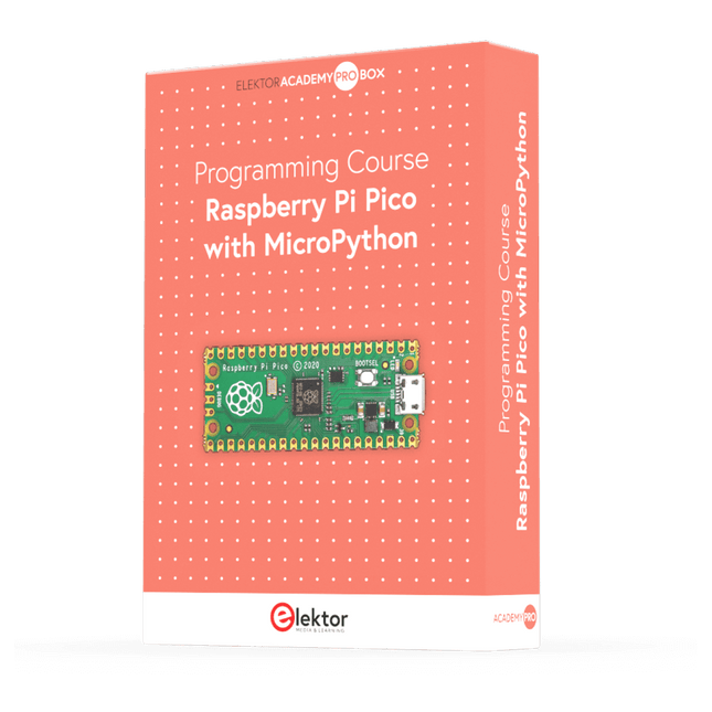
This complete Raspberry Pi Pico microcontroller programming course features a textbook, a component kit, hands-on projects, and a comprehensive online course with simulations. It is ideal for step-by-step learning of embedded systems programming in MicroPython using a practical, hands-on approach.
A Practical Introduction to Embedded Systems with the Raspberry Pi Pico
This course is designed for people who are new to embedded systems and looking for a structured, example-driven way to get started.
A kit of parts comprising LEDs and resistors, switches, sensors and actuators, displays, a breadboard and wires, and more is included. These are used in the course to illustrate example applications.
No prior experience with Arduino or embedded development is required. Each section features hands-on examples and mini projects designed to reinforce key concepts and inspire deeper exploration. By the end of the course, you’ll be able not only to reproduce the examples but also to build on them with your own ideas and applications.
What Will You Learn?
Microcontroller programming in MicroPython with the Raspberry Pi Pico using the Thonny IDE
Working with Digital I/O, read buttons and encoders, control LEDs and relays
Read analog inputs, voltages, and analog sensors
Generating analog output signals and PWM
Use serial communication like UART, I²C and SPI to control displays and read digital sensors and SD cards
Managing time
Working with interrupts
Real-time sensor input and control via buttons, LEDs, and displays
Control actuators like relays and servo motors
Who Is It For?
Students and self-learners exploring embedded systems
Makers and IoT enthusiasts looking to improve their hardware skills
Educators and trainers seeking ready-to-teach material
What's Inside the Box?
Access to the full course on the Elektor Academy Pro Learning Platform
Raspberry Pi Pico microcontroller board + USB cable
Book: Programming Microcontrollers in MicroPython
Downloadable project files for every module
Component Box:
2× LED, red, 5 mm
LED, green, 5 mm
3× Resistor, 470 Ω, 0.25 W
LDR
Potentiometer, 10 kΩ, linear
Pushbutton
Rotary encoder module
Relay module
DHT22 Humidity & Temperature Sensor
TM1637-compatible 4-digit 7-segment display
MPU-6050 IMU with headers
SSD1306-compatible I²C OLED display
Micro SD card adapter with header
Buzzer
SG90 Micro Servo
ILI9341-compatible SPI 240×320 TFT display
20× Jumper wires
Breadboard
All Programming Courses (and differences in content)
Course
Arduino
Raspberry Pi Pico with Arduino C/C++
ESP32 with Arduino C/C++
Raspberry Pi Pico with MicroPython
ESP32 with MicroPython
Online Course
Access to Arduino Course
Access to Pico with Arduino C/C++ Course
Access to ESP32 with Arduino C/C++ Course
Access to Pico with MicroPython Course
Access to ESP32 with MicroPython Course
Board
Uno R3
Raspberry Pi Pico
ESP32
Raspberry Pi Pico
ESP32
Book
Programming Microcontrollers in C/C++ Using Arduino
Programming Microcontrollers in C/C++ Using Arduino
Programming Microcontrollers in C/C++ Using Arduino
Programming Microcontrollers in MicroPython
Programming Microcontrollers in MicroPython
Kit
40-piece Component Box
40-piece Component Box
40-piece Component Box
40-piece Component Box
40-piece Component Box
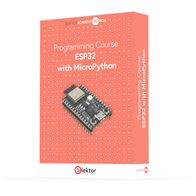
This complete ESP32 microcontroller programming course features a textbook, a component kit, hands-on projects, and a comprehensive online course with simulations. It is ideal for step-by-step learning of embedded systems programming in MicroPython using a practical, hands-on approach.
A Practical Introduction to Embedded Systems with the ESP32
This course is designed for people who are new to embedded systems and looking for a structured, example-driven way to get started.
A kit of parts comprising LEDs and resistors, switches, sensors and actuators, displays, a breadboard and wires, and more is included. These are used in the course to illustrate example applications.
No prior experience with Arduino or embedded development is required. Each section features hands-on examples and mini projects designed to reinforce key concepts and inspire deeper exploration. By the end of the course, you’ll be able not only to reproduce the examples but also to build on them with your own ideas and applications.
What Will You Learn?
Microcontroller programming in MicroPython with the ESP32 using the Thonny IDE
Working with Digital I/O, read buttons and encoders, control LEDs and relays
Read analog inputs, voltages, and analog sensors
Generating analog output signals and PWM
Use serial communication like UART, I²C and SPI to control displays and read digital sensors and SD cards
Managing time
Working with interrupts
Real-time sensor input and control via buttons, LEDs, and displays
Control actuators like relays and servo motors
Who Is It For?
Students and self-learners exploring embedded systems
Makers and IoT enthusiasts looking to improve their hardware skills
Educators and trainers seeking ready-to-teach material
What's Inside the Box?
Access to the full course on the Elektor Academy Pro Learning Platform
ESP32 microcontroller board + USB cable
Book: Programming Microcontrollers in MicroPython
Downloadable project files for every module
Component Box:
2× LED, red, 5 mm
LED, green, 5 mm
3× Resistor, 470 Ω, 0.25 W
LDR
Potentiometer, 10 kΩ, linear
Pushbutton
Rotary encoder module
Relay module
DHT22 Humidity & Temperature Sensor
TM1637-compatible 4-digit 7-segment display
MPU-6050 IMU with headers
SSD1306-compatible I²C OLED display
Micro SD card adapter with header
Buzzer
SG90 Micro Servo
ILI9341-compatible SPI 240×320 TFT display
20× Jumper wires
Breadboard
All Programming Courses (and differences in content)
Course
Arduino
Raspberry Pi Pico with Arduino C/C++
ESP32 with Arduino C/C++
Raspberry Pi Pico with MicroPython
ESP32 with MicroPython
Online Course
Access to Arduino Course
Access to Pico with Arduino C/C++ Course
Access to ESP32 with Arduino C/C++ Course
Access to Pico with MicroPython Course
Access to ESP32 with MicroPython Course
Board
Uno R3
Raspberry Pi Pico
ESP32
Raspberry Pi Pico
ESP32
Book
Programming Microcontrollers in C/C++ Using Arduino
Programming Microcontrollers in C/C++ Using Arduino
Programming Microcontrollers in C/C++ Using Arduino
Programming Microcontrollers in MicroPython
Programming Microcontrollers in MicroPython
Kit
40-piece Component Box
40-piece Component Box
40-piece Component Box
40-piece Component Box
40-piece Component Box
From Simple Ciphers to Secure Systems
Understanding how to apply cryptography on modern microcontrollers is essential for building secure, reliable, and trustworthy systems. This book explains cryptography in the context of embedded hardware, from classical ciphers that illustrate core principles to modern techniques such as AES for practical high-security applications.
By combining mathematical theory with real-world microcontroller implementations, readers learn not only how cryptography works, but also how to implement it effectively on systems with limited processing power and memory. The book is intended for students starting out in cryptography, hobbyists securing personal projects, and engineers looking for a structured guide to embedded security.
The book covers these key topics in applied cryptography:
Classical ciphers on Arduino Uno and Raspberry Pi Pico, with full programs: Spartan Scytale, Hebrew Atbash, Caesar, ROT13, Alberti Disk, Vigenère, Affine, Polybius, Playfair, Beaufort, Ottoman Codebook, and One-Time Pad.
Hacking classical ciphers using microcontrollers, with examples.
Pseudo-random (PRNG) and true random number generation (TRNG) on microcontrollers.
Symmetric-key cryptography with full programs: DES and AES-128/256.
Memory and speed constraints of cryptography on microcontrollers.
Asymmetric cryptography: public/private keys, digital signatures, key distribution and derivation (KDF), RSA, and SHA-256 implementations.
A complete secure communication program using RSA and AES-256.
A glossary of commonly used cryptography terms.
AI Projects for the Raspberry Pi with the AI HAT+
Edge AI is transforming everyday devices by putting intelligence where it matters most: directly inside the hardware. With on-device inference, a camera can recognize a visitor instantly, a phone can translate speech without streaming audio to the cloud, and a wearable can detect anomalies in real time—fast, private, and reliable even when the network disappears.
This book is your practical guide to building exactly those kinds of systems with the Raspberry Pi AI HAT+ and the Hailo-8L accelerator. You’ll start with clear foundations: core AI and machine-learning concepts, how neural networks work, and what truly distinguishes Edge AI from cloud AI—plus an honest look at ethical considerations and future impacts.
Then it’s straight to hands-on physical computing. Step by step, you’ll set up Raspberry Pi OS, power and cooling, and develop in Python using the Thonny IDE. You’ll learn GPIO basics with lights and servos, mount the AI HAT+ hardware, install and verify the Hailo software stack, and connect the right camera—official modules or USB webcams, even multiple cameras.
From your first pipeline to real projects, you’ll run person detection, pose estimation, segmentation, and depth estimation, then level up with YOLO object detection: smart alerts, guest counters, and custom extensions. You’ll even connect vision to motion by combining gesture recognition with servo-driven mechanisms, including a robotic arm.
With troubleshooting tips, hardware essentials, and a practical Python refresher, this book turns Edge AI from buzzword into buildable reality.
The Basics, New Ideas & Applications
Build digital electronics from the ground up—and take it all the way to practical circuits you can use.
This book guides you through the core principles of digital technology with a strongly hands-on approach. You’ll begin with the essentials: signals, devices for working with them, and what "logic 0" and "logic 1" mean in real hardware. Simple demonstration setups made from easy-to-find parts (LEDs, diodes, resistors, switches) help you see how logic behaves, making the theory click before you move on.
From there, you’ll explore a wide range of logic elements and how they’re implemented, including classic logic families such as TTL and CMOS. The fundamentals section covers the building blocks of digital systems: flip-flops, Schmitt triggers, registers, counters and dividers, encoders/ decoders, multiplexers/demultiplexers, plus A/D and D/A conversion and timing circuits.
Next, the book invites you into "new ideas" in digital electronics—universal logic elements, unconventional approaches (including thyristor-based and fractional logic), and creative logic functions that can inspire original designs.
Finally, a large, well-organized collection of application circuits turns knowledge into projects: electronic switches and selectors, pulse generators, PWM regulators, frequency multipliers/dividers, phase shifters, and digital filters.
Study it deeply, and you’ll gain not only understanding—but the ability to design and debug digital circuits independently.
DEAL: Order the HackRF Pro now and get the new e-book "SDR with HackRF One & HackRF Pro" worth €20 for FREE!
HackRF Pro is latest Software Defined Radio (SDR) from Great Scott Gadgets and the powerful successor to the legendary HackRF One. With a frequency range from 100 kHz to 6 GHz, it covers an enormous spectrum for transmitting and receiving radio signals.
Designed as an open-source hardware platform, the HackRF Pro is the ideal tool for analyzing and developing modern wireless technologies. It can be used flexibly as a USB peripheral or programmed for standalone operation.
Specifications
Frequency: 100 kHz to 6 GHz
Adjustable from 0 Hz to 7.1 GHz
Half-duplex transceiver
Up to 20 million samples per second
8-bit quadrature samples (8-bit I and 8-bit Q)
Compatible with GNU Radio, SDR#, and more
Software-configurable RX and TX gain and baseband filter
Software-controlled RF port power (50 mA at 3.3 V)
SMA RF connector
SMA clock input and output for synchronization and triggering
Convenient buttons for programming
Internal pin headers for expansion
High-Speed USB 2.0 with USB-C connector
USB-powered
Open source hardware
Compared to its predecessor, HackRF Pro offers a variety of new features, including:
Wider operating frequency range
Improved RF performance with flatter frequency response
USB-C connector
Built-in TCXO crystal oscillator for superior timing stability
Logic upgrade from a CPLD to a power-efficient FPGA
Elimination of the DC spike
Extended-precision mode with 16-bit samples for low sample rates (typical ENOB: 9-11)
Half-precision mode with 4-bit samples at up to 40 Msps
More RAM and flash memory for custom firmware
Installed shielding around the radio section
Trigger input and output accessible through clock connectors
Cutout in the PCB provides space for future add-ons
Improved power management
Enhanced RF port protection
Facility to hardware-disable transmit mode
Full Compatibility: Thanks to its proven architecture, existing software for the HackRF One can also be used directly with the HackRF Pro. The HackRF Pro offers seamless backward compatibility while significantly increasing performance.
Note: An antenna is not included. We recommend the ANT500 for the best experience.
Included
HackRF Pro SDR with plastic enclosure
NEW e-book: SDR with HackRF One & HackRF Pro (normal price: €20)
Downloads
Documentation
GitHub
Principles, Systems, and Electronics
This handbook provides a detailed study of the sensors and actuators at the heart of modern vehicle electronics. It begins with basic electrical and electronic concepts, introducing the principles and terminology essential for understanding automotive systems.
The book explores sensors and actuators on a system-by-system basis, including:
Fundamentals of electrical engineering, electromagnetic phenomena, and motor principles
Passive and active electronic components, integrated circuits, protection devices, and automotive-grade electronics
Sensor characteristics, signal conditioning, ADCs, PWM and frequency outputs, and interface adaptation
Automotive communication links and protocols, including LIN and SENT
Engine sensors: air mass, pressure, temperature, speed, position, exhaust and emissions-related sensors
Transmission sensors for manual and automatic systems
Steering and suspension sensors for conventional and active systems
Vehicle body and electrical system sensors for comfort, climate, access, and monitoring functions
Engine actuators such as throttle bodies, injectors, turbo actuators, EGR systems, ignition components, and pumps
Transmission, brake, steering, suspension, and body actuators
Identification and coding of electronic components and packages commonly used in automotive applications
The structure and operating principles of each component are explained, with relevant electronic circuitry illustrated. Its system-oriented organization and practical focus make it a valuable reference for understanding, testing, and troubleshooting automotive electronic systems.
Practical Guide to Modular RF Design
Build Your Own Software-Defined Radio combines RF circuitry with hardware programming and PC-based signal processing. The e-book presents a modular approach to building a complete SDR system using RF Bricks – from the mechanical framework and RF modules to measurement tools, PC software, and FPGA implementations. Practical explanations guide readers through real signal paths, construction steps, and measurement routines, linking hardware and software into a flexible SDR platform.
Key topics include:
Mechanical setup: RF Brick template, chassis, and 19-inch module carrier
Bridges: USB isolator, I²C level shifter, I²C power switch, and practical examples
Signal-chain design with RF Bricks: antennas, band filters, NanoVNA work, preamplifiers, PLLs, demodulators, direct-conversion chains, multiband options, and narrowband bricks
RF measurement Bricks: single- and dual-tone sources, NPR methods, noise generators, notch filters, broadband amplifiers, and impedance bridges
Useful accessories: ATU-100 tuner, X-Phase QRM eliminator, and firmware notes
PC host software: SoapyAudio adjustments, GQRX, SDR++, and added functionality
GnuRadio elements: control blocks, SSB demodulation, GUI components, messaging, and filter handling
FPGA-based SDR: VHDL, toolchains, ADC/DAC blocks, oversampling, and a complete SSB/CW signal chain
With its modular structure and detailed working examples, this e-book offers a practical path to building and extending modern SDR systems.
Downloads
Software
Elektor GREEN and GOLD members can download their digital edition here.
Not a member yet? Click here.
Low-Noise Lab Power Supply (1)A Quiet Source for Sensitive Circuits
STM32 Edge AI Contest 2025: The Winners
Batteries TodayTechnology and Differences in Lithium Batteries
Adjustable Electronic LoadStatic + Dynamic DC Load
Step-Down Converter from 48 V to 5 VThe Story of Circuit Development
Autonomous Sensor Node v2.0Part 2: Hardware Validation and Power Optimizations
VaristorsPeculiar Parts, the Series
Graphical Grid Frequency MeterMonitor Grid Quality
Starting Out in Electronics……Brings Its Own End
Peak Current Load SMD FerritesMore Resilient Against Current Peaks
Elektor Live! Expert Day 2025
Energy Harvesting Set to Accelerate IoT and IIoT Use CasesHow Energy Harvesting Frees IoT from the Grid
Fnirsi DPS-150Compact and Portable Power Supply and Converter
Adjustable USB-C Power SourceTurn Your USB-C Charger Into an Adjustable Power Supply
Simple Charger and Capacity TesterWith Two Cheap “Off-the-Shelf” Modules
Smart Color Detector with AI Voice and Playback
PbMonitor v2.0Introduction to the Updated Battery Monitoring System
A Fan for the Mini Reflow PlateSmart Modifications That Improve Results
From Life’s ExperienceThe Tsunami of Indulgence
Err-lectronicsCorrections, Updates, and Readers’ Letters
2026: An AI OdysseyWhen Models Start Dictating the Hardware
Precision Picoammeter (2)Assembling, Calibration, and Test
Wireless Device Poweringwith Inductive Technology
AI-Based Autonomous DrivingThe RDW’s Self Driving Challenge 2024
Sound Card as Signal GeneratorPC as DCF77 Test Transmitter
Designing, Wiring, and Controlling
Build Your Own Coffee Roaster is a practical guide to constructing and operating the Cobra Smart Roaster and its companion Open Roaster Controller (ORC).
The e-book walks the reader through every stage of the build, from assembling the powerhead and wiring the system to installing and configuring the controller. Along the way, you’ll learn how to use the Raspberry Pi to bring precision and flexibility to your roasting process.
Clear, step-by-step chapters cover:
Powerhead construction and required components
Low- and high-voltage wiring
Installing the ORC, network setup, and using the web interface
Roasting coffee with the Cobra in different setups, including hand-stir and bread-machine roasting
Advanced topics such as manual mode, fixed profiles, Artisan-Scope connections, and ORC system programming
A complete parts list, practical guidance throughout, and concise explanations make this e-book a useful reference for anyone interested in building, modifying, or understanding their own coffee-roasting system.