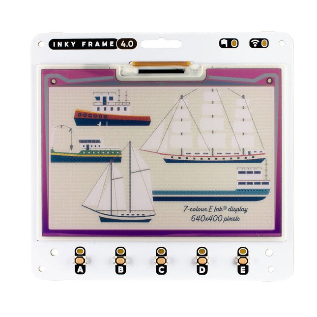
Inky Frame 4.0" features a vibrant E Ink display with 640 x 400 pixels of tightly packed seven colour goodness – that's almost as many pixels as on the 5.7" Inky Frame, but squished tidily into a smaller footprint. There's five buttons with LED indicators for interacting with the display, two Qw/ST connectors for plugging in breakouts and a micro SD card slot for storage of capybara photos or other vital files.
Every Inky Frame comes with a pair of sleek little metal legs so you can stand it up on your desk. There's also a battery connector so you can power it without annoying trailing wires, and some neato power saving features that mean you can run it from batteries for ages.
Inky Frame 4.0" is great for:
An ultra readable, low power consumption home automation dashboard
Displaying stylised photos, pop art images or favourite comic panels.
Showing cute graphs and readouts from local or wirelessly connected sensors
Displaying fascinating data from online APIs.
Features
Raspberry Pi Pico W Aboard
Dual Arm Cortex M0+ running at up to 133 Mhz with 264 kB of SRAM
2 MB of QSPI flash supporting XiP
Powered and programmable by USB micro-B
2.4 GHz wireless
4.01' EPD display (640 x 400 pixels)
E Ink Gallery Palette 4000 ePaper
ACeP (Advanced Color ePaper) 7-color with black, white, red, green, blue, yellow, orange.
Ultra wide viewing angles
Ultra low power consumption
Dot pitch – 0.135 x 0.135 mm
5x Tactile buttons with LED indicators
Two Qw/ST connectors for attaching breakouts
microSD card slot
Dedicated RTC chip (PCF85063A) for deep sleep/wake
Fully assembled (no soldering required)
C/C++ and MicroPython libraries
Schematic
Included
1x Inky Frame 4.0' (incl. Pico W)
2x Metal legs
Downloads
MicroPython
(Learn) Getting Started with Inky Frame
(Readme) Installing MicroPython
(Readme) MicroPython FAQs (and troubleshooting)
Download pirate-brand MicroPython (you'll want the Inky Frame.uf2)
MicroPython examples
PicoGraphics function reference
C/C++
C examples
Picographics function reference
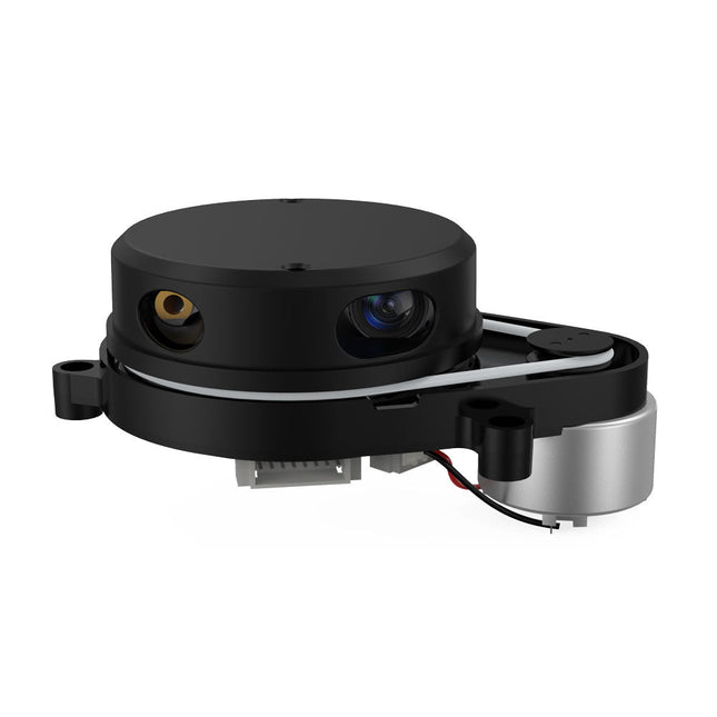
YDLIDAR X4PRO is a 360 degrees two-dimensional rangefinder. Based on the principle of triangulation, it is equipped with related optics, electricity, and algorithm design to achieve high-frequency and high-accuracy distance measurement. The mechanical structure rotates 360 degrees to continuously output the angle information as well as the point cloud data of the scanning environment while ranging.
Features
360 degrees omnidirectional scanning ranging distance measurement
Small distance error, stable performance and high accuracy
Wide ranging distance
Strong resistance to ambient light interference
Low power consumption, small size and long service life
Laser power meets Class I laser safety standards
Adjustable motor speed, scanning frequency is 6~12 Hz
High-speed ranging, ranging frequency up to 5 kHz
Applications
Robot navigation and obstacle avoidance
Robot ROS teaching and research
Regional security
Environmental scanning and 3D reconstruction
Navigation and obstacle avoidance of robot vacuum cleaner/ROS Learning robot
Specifications
Range Frequency
5000 Hz
Scan Frequency
6-12 Hz
Range Distance
0.12-10 m
Scan Angle
360°
Angle Resolution
0.43-0.85°
Dimensions
110.6 x 71.1 x 52.3 mm
Downloads
Datasheet
User Manual
Development Manual
SDK
Tool
ROS
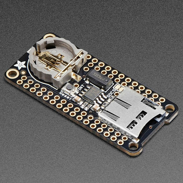
This FeatherWing will make it easy to add data logging to any Feather Board you might have. You get both an I²C real-time clock (PCF8523) with 32 KHz crystal and battery backup, and a microSD socket that connects to the SPI port pins (+ extra pin for CS). Note: FeatherWing doesn't come with a microSD card. A CR1220 coin cell is required to use the RTC battery-backup capabilities. If you're not using the RTC part of the FeatherWing, a battery is not required. To talk to the microSD card socket Arduino's default SD library is recommended. Some light soldering is required to attach the headers onto the Wing. Pinouts Power pins On the bottom row, the 3.3 V (second from left) and GND (fourth from left) pin are used to power the SD card and RTC (to take a load off the coin cell battery when main power is available) RTC & I²C Pins In the top right, SDA (rightmost) and SCL (to the left of SDA) are used to talk to the RTC chip.
SCL - I²C clock pin to connect to your microcontroller's I2C clock line. This pin has a 10 kΩ pull-up resistor to 3.3 V
SDA - I²C data pin to connect to your microcontroller's I2C data line. This pin has a 10 kΩ pull-up resistor to 3.3 V There's also a breakout for INT which is the output pin from the RTC. It can be used as an interrupt output or it could also be used to generate a square wave. Note that this pin is an open drain - you must enable the internal pull-up on whatever digital pin it is connected to. SD & SPI Pins Starting from the left you've got SPI Clock (SCK) - output from feather to wing SPI Master Out Slave In (MOSI) - output from feather to wing SPI Master In Slave Out (MISO) - input from wing to feather These pins are in the same location on every Feather. They are used for communicating with the SD card. When the SD card is not inserted, these pins are completely free. MISO is tri-stated whenever the SD CS (chip select) pin is pulled high
This carrier board combines a 2.4" TFT display, six addressable LEDs, onboard voltage regulator, a 6-pin IO connector, and microSD slot with the M.2 pin connector slot so that it can be used with compatible processor boards in our MicroMod ecosystem. We've also populated this carrier board with Atmel's ATtiny84 with 8kb of programmable flash. This little guy is preprogrammed to communicate with the processor over I²C to read button presses.
Features
M.2 MicroMod Connector
240 x 320 pixel, 2.4" TFT display
6 Addressable APA102 LEDs
Magnetic Buzzer
USB-C Connector
3.3 V 1 A Voltage Regulator
Qwiic Connector
Boot/Reset Buttons
RTC Backup Battery & Charge Circuit
microSD
Phillips #0 M2.5 x 3 mm screw included
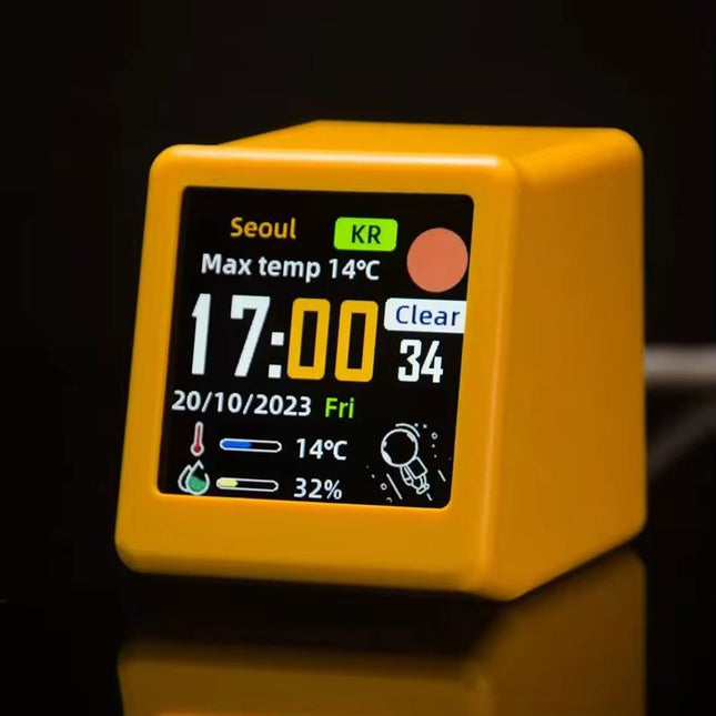
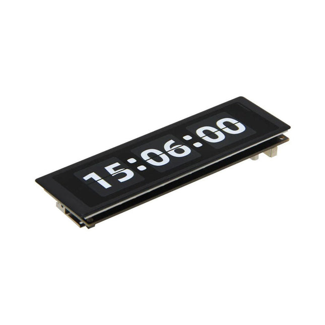
This portable WiFi weather station is the perfect blend of functionality and style, offering real-time updates on temperature, humidity, and time – all at a single glance.
Featuring a clear digital display, the station ensures that weather and time data are always easy to read and understand. Its minimalist design integrates seamlessly into any environment, adding a touch of modern sophistication without drawing unnecessary attention.
Features
Multi-Function Display: Shows weather, atmospheric pressure, min/max temperature, wind speed, city, country/region, date, day of the week, outdoor temperature & humidity – all at a glance.
Custom GIF Animations: Upload your own GIFs for a personalized display experience.
WiFi Connectivity: Automatically connects to the Internet to retrieve real-time weather and time data.
Power Supply: USB-C
Durable Plastic Casing
Dimensions: 45 x 35 x 40 mm
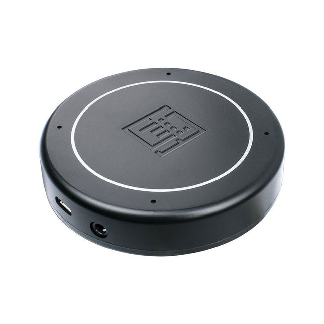
Features
Plug & Play (No driver required), compatible with Windows 10/8/7, Mac, Linux and Android that support OTG.
Voice Pick-up device, Far-field voice pick-up up to 5m and supports 360° pick-up pattern
Acoustic algorithms implemented:
DOA(Direction of Arrival),
AEC(Automatic Echo Cancellation),
AGC(Automatic Gain Control),
NS(Noise Suppression)
Built-in audio jack, which allows for plugging in headphones or speakers (speaker not included)
Applications
Voice pick-up device
Home/Office automation device
In-car voice assistant
Healthcare device
Voice interaction robot
Other applications
Specifications
XVF-3000 from XMOS
4 High-Performance Digital Microphones
Supports Far-field Voice Capture
Speech Algorithms On-Chip
12 Programmable RGB LED Indicators
Microphones: MEMS MSM261D4030H1CPM
Sensitivity: -26 dBFS (Omnidirectional)
Acoustic Overload Point: 120 dB SPL
SNR: 63 dB
Power Supply: 5V DC from Micro USB or Expansion Header
Dimensions: 77mm (Diameter)
3.5mm Audio Jack Output Socket
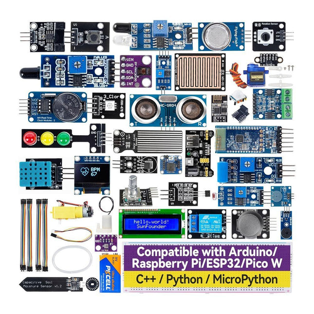
Discover endless creativity with the Universal Maker Sensor Kit, designed for use with Raspberry Pi, Pico W, Arduino, and ESP32. This versatile kit offers compatibility across popular development platforms, including Arduino Uno R4 Minima/WiFi, Uno R3, Mega 2560, Raspberry Pi 5, 4, 3B+, 3B, Zero, Pico W, and ESP32.
Featuring over 35 sensors, actuators, and displays, it's perfect for projects ranging from environmental monitoring and smart home automation to robotics and interactive gaming. Step-by-step tutorials in C/C++, Python, and MicroPython guide beginners and experienced makers alike through 169 exciting projects.
Features
Wide Compatibility: Fully supports Arduino (Uno R3, Uno R4 Minima/WiFi, Mega 2560), Raspberry Pi (5, 4, 3B+, 3B, Zero, Pico W), and ESP32, enabling extensive flexibility across numerous development platforms. Includes instructions for building 169 projects.
Comprehensive Components: Features more than 35 sensors, actuators, and display modules suitable for diverse projects such as environmental monitoring, smart home automation, robotics, and interactive game controllers.
Detailed Tutorials: Provides clear, step-by-step tutorials covering Arduino, Raspberry Pi, Pico W, ESP32, and each included component. Tutorials are available in C/C++, Python, and MicroPython, catering effectively to both beginners and experienced makers.
Suitable for All Skill Levels: Offers structured projects designed to guide users seamlessly from beginner to advanced proficiency in electronics and programming, enhancing creativity and technical expertise.
Included
Breadboard
Button Module
Capacitive Soil Moisture Module
Flame Sensor Module
Gas/Smoke Sensor Module (MQ2)
Gyroscope & Accelerometer Module (MPU6050)
Hall Sensor Module
Infrared Speed Sensor Module
IR Obstacle Avoidance Sensor Module
Joystick Module
PCF8591 ADC DAC Converter Module
Photoresistor Module
PIR Motion Module (HC-SR501)
Potentiometer Module
Pulse Oximeter and Heart Rate Sensor Module (MAX30102)
Raindrop Detection Module
Real Time Clock Module (DS1302)
Rotary Encoder Module
Temperature Sensor Module (DS18B20)
Temperature and Humidity Sensor Module (DHT11)
Temperature, Humidity & Pressure Sensor (BMP280)
Time of Flight Micro-LIDAR Distance Sensor (VL53L0X)
Touch Sensor Module
Ultrasonic Sensor Module (HC-SR04)
Vibration Sensor Module (SW-420)
Water Level Sensor Module
I²C LCD 1602
OLED Display Module (SSD1306)
RGB LED Module
Traffic Light Module
5 V Relay Module
Centrifugal Pump
L9110 Motor Driver Module
Passive Buzzer Module
Servo Motor (SG90)
TT Motor
ESP8266 Module
JDY-31 Bluetooth Module
Power Supply Module
Documentation
Online Tutorial
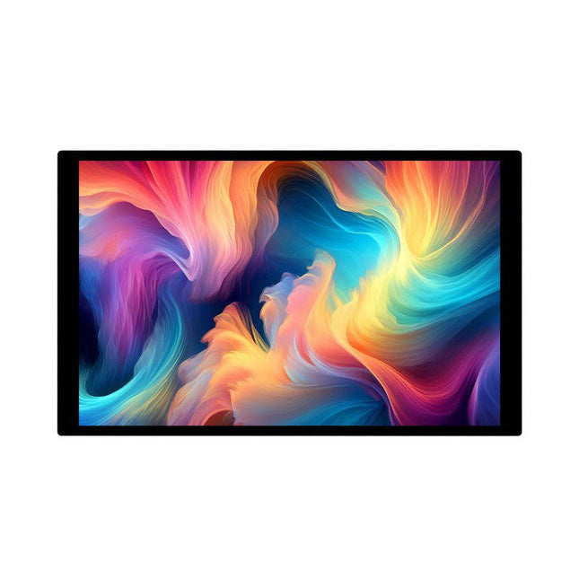
The Waveshare 10.1-inch High-Resolution Capacitive Touch Display is a universal touchscreen with 1920 x 1200 resolution, compatible with most standard HDMI devices. It features a thin and lightweight design, a rigid tempered glass cover for durability, excellent display performance, and a smooth multi-touch experience. Additionally, the built-in metal backplate provides stability, making it easier for users to integrate the display into all-in-one projects.
Features
10.1-inch IPS screen with 1920 x 1200 pixels
10-point capacitive touch with tempered glass panel offering up to 6H hardness
Fully laminated panel technology for better display effect
When used with Raspberry Pi, it supports Raspberry Pi OS, Ubuntu, Kali, and RetroPie
As a computer monitor, it supports Windows 7 and higher.
OSD menu (can be used for power control, adjusting brightness/volume/picture rotation, etc.)
HDMI audio output, onboard 3.5 mm headphone jack and 4-pin high-quality speakers
Specifications
Display
10.1 inch IPS
Viewing angle
178°
Resolution
1920 x 1200 pixels
Touchscreen area
217.2 x 135.6 mm
Dimensions
239 x 147 mm
Color gamut
65% NTSC
Max brightness
300 cd/m²
Contrast
1000:1
Backlight adjustment
Button dimming
Refresh rate
60 Hz
Display interface
Standard HDMI
Power supply
5 V (USB-C)
Max power consumption
6 W
Included
1x 10.1" High-Res Capacitive Touch Display (10.1EP-CAPLCD)
1x HDMI flat cable (1 m)
1x USB-A to USB-C cable (1 m)
1x Micro HDMI Adapter
1x HDMI Adapter
1x HDMI to Micro HDMI Adapter
1x PH1.25 4-pin to Type-A cable
1x Capacitive touch pen
1x 3-pin cable
1x HDMI cable 120 mm (2pcs)
1x Cleaning cloth
1x 5 V/3A power supply (EU)
1x Screws pack
Downloads
Wiki
The iCEBreaker FPGA board is an open-source educational FPGA development board.
The iCEBreaker is great for classes and workshops teaching the use of the open source FPGA design flow through Yosys, nextpnr, IceStorm, Icarus Verilog, Amaranth HDL and others. This means the board is low cost and has a nice set of features to allow for the design of interesting classes and workshop exercises. At the same time it allows the user to use the proprietary vendor tools if they choose to.
After the workshop the boards can be easily used as a development board as most GPIO are exposed, broken out and configurable through jumpers on the back of the board. There is only a minimal amount of buttons and LED that can't be disconnected and used for your own purposes.
Documentation
Workshop
The Sparkfun Qwiic GPIO is an I²C device based around the TCA9534 I/O Expander IC from Texas Instruments. The board adds eight IO pins that you can read and write just like any other digital pin on your controller. The details of the I²C interface have been taken care of in an Arduino library so you can call functions similar to Arduino's pinMode and digitalWrite, allowing you to focus on your creation! The TCA9534's pins are broken out to easy-to-use latch terminals; never screw another wire into place! The terminals are relatively roomy themselves, so feel free to latch multiple wires into a ground or power terminal. With three customizable address jumpers, you can have up to eight Qwiic GPIO boards connected on a single bus allowing upwards of 64 additional GPIO pins! The default I²C is 0x27 and can be changed by adjusting the jumpers on the board's back. Features Eight Configurable GPIO Pins Available I²C Address: 0x27 (Default) Hardware address pins allow up to eight boards on a single bus Input Polarity Inversion Register Control each I/O pin individually or all at once Open-Drain Active-Low Interrupt Output 2x Qwiic Connectors Dimensions: 60.96 x 38.10 mm
The LILYGO T-Display-S3 Long is a versatile development board powered by the ESP32-S3R8 dual-core LX7 microprocessor. It features a 3.4-inch capacitive touch TFT LCD with a resolution of 180x640 pixels, providing a responsive interface for various applications.
This board is ideal for developers seeking a compact yet powerful solution for projects requiring touch input and wireless communication. Its compatibility with popular programming environments ensures a smooth development experience.
Specifications
MCU
ESP32-S3R8 Dual-core LX7 microprocessor
Wireless Connectivity
Wi-Fi 802.11, BLE 5 + BT Mesh
Programming Platform
Arduino IDE, VS Code
Flash
16 MB
PSRAM
8 MB
Bat voltage detection
IO02
Onboard functions
Boot + Reset Button, Battery Switch
Display
3.4" Capacitive Touch TFT LCD
Color depth
565, 666
Resolution
180 x 640 (RGB)
Working power supply
3.3 V
Interface
QSPI
Included
1x T-Display S3 Long
1x Power cable
2x STEMMA QT/Qwiic interface cable (P352)
1x Female pin (double row)
Downloads
GitHub
The Power Delivery Board uses a standalone controller to negotiate with the power adapters and switch to a higher voltage other than just 5V. This uses the same power adapter for different projects rather than relying on multiple power adapters to provide different output; it can deliver the board as part of SparkFun’s Qwiic connect system, so you won’t have to do any soldering to figure out how things are oriented.
The SparkFun Power Delivery Board takes advantage of the power delivery standard using a standalone controller from STMicroelectronics, the STUSB4500. The STUSB4500 is a USB power delivery controller that addresses sink devices. It implements a proprietary algorithm to negotiate a power delivery contract with a source (i.e. a power delivery wall wart or power adapter) without the need for an external microcontroller. However, you will need a microcontroller to configure the board. PDO profiles are configured in an integrated non-volatile memory. The controller does all the heavy lifting of power negotiation and provides an easy way to configure over I²C.
To configure the board, you will need an I²C bus. The Qwiic system makes it easy to connect the Power Delivery board to a microcontroller. Depending on your application, you can also connect to the I²C bus via the plated through SDA and SCL holes.
Features
Input and output voltage range of 5-20V
Output current up to 5A
Three configurable power delivery profiles
Auto-run Type-C™ and USB PD sink controller
Certified USB Type-C™ rev 1.2 and USB PD rev 2.0 (TID #1000133)
Integrated VBUS voltage monitoring
Integrated VBUS switch gate drivers (PMOS)
LuckFox Pico Mini is a compact Linux micro development board based on the Rockchip RV1103 chip, providing a simple and efficient development platform for developers. It supports a variety of interfaces, including MIPI CSI, GPIO, UART, SPI, I²C, USB, etc., which is convenient for quick development and debugging.
Features
Single-core ARM Cortex-A7 32-bit core with integrated NEON and FPU
Built-in Rockchip self-developed 4th generation NPU, features high computing precision and supports int, int8, and int16 hybrid quantization. The computing power of int8 is 0.5 TOPS, and up to 1.0 TOPS with int4
Built-in self-developed third-generation ISP3.2, supports 4-Megapixel, with multiple image enhancement and correction algorithms such as HDR, WDR, multi-level noise reduction, etc.
Features powerful encoding performance, supports intelligent encoding mode and adaptive stream saving according to the scene, saves more than 50% bit rate of the conventional CBR mode so that the images from camera are high-definition with smaller size, double the storage space
Built-in RISC-V MCU supports low power consumption and fast start-up, supports 250 ms fast picture capture and loading Al model library at the same time to realize face recognition "in one second"
Built-in 16-bit DRAM DDR2, which is capable of sustaining demanding memory bandwidths
Integrated with built-in POR, audio codec and MAC PHY
Specifications
Processor
ARM Cortex-A7, single-core 32-bit CPU, 1.2 GHz, with NEON and FPU
NPU
Rockchip 4th-gen NPU, supports int4, int8, int16; up to 1.0 TOPS (int4)
ISP
Third-gen ISP3.2, up to 4 MP input at 30fps, HDR, WDR, noise reduction
RAM
64 MB DDR2
Storage
128 MB SPI NAND Flash
USB
USB 2.0 Host/Device via Type-C
Camera Interface
MIPI CSI 2-lane
GPIO Pins
17 GPIO pins
Power Consumption
Low power, RISC-V MCU for fast startup
Dimensions
28 x 21 mm
Downloads
Wiki
After power on, YDLIDAR G4 start rotating and scanning the environment around it. The scanning distance is 16 m and the device offers a scanning rate of 9,000 times per second.
It makes detailed examinations of its environment and can locate the smallest of objects surrounding it. Featuring a high-precision brushless motor and encoder disc mounted on bearings, it rotates smoothly and has a service life of up to 500,000 hours of operation.
The G4 is an inexpensive solution for projects that require obstacle detection, obstacle avoidance, and/or simultaneous localization and mapping (SLAM). All YDLIDAR products are ROS ready.
Features
360 degree 2D range scanning
Stable performance, high precision
16 m range
Strong resistance to environmental light interference
Brushless motor drive, stable performance
FDA Laser safety standard Class I
360 degree omnidirectional scanning, 5-12 Hz adaptive scanning frequency
OptoMagnetic technology
Wireless data communication
Scanning rate of 9000 Hz
Downloads
Datasheet
User Manual
Development Manual
SDK
Tool
ROS
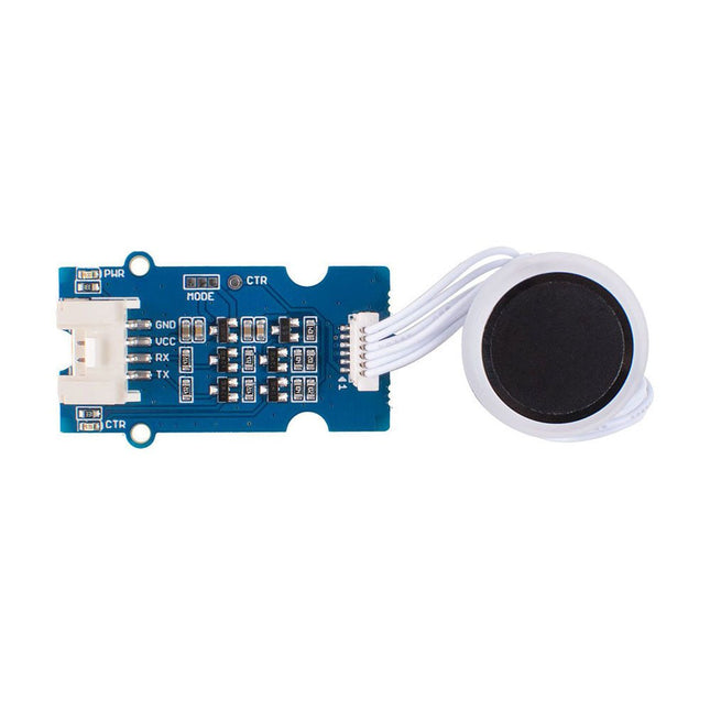
The Grove Capacitive Fingerprint Scanner/Sensor is based on the KCT203 Semiconductor fingerprint recognition module, including a high-performance MCU, a vertical RF push-type fingerprint sensor, and a touch sensing device.
This module features many advantages such as small size, small fingerprint template, low power consumption, high reliability, fast fingerprint recognition, etc. In addition, it is worth mentioning that there is a lovely RGB light around this module to indicate whether the fingerprint recognition is successful.
The system is equipped with a high-performance fingerprint algorithm, and the self-learning function is remarkable. After each successful fingerprint recognition, the latest challenge feature values can be integrated into the fingerprint database to continuously improve the fingerprint features, making the experience better.
Applications
Fingerprint lock devices: door locks, safes, steering wheel locks, padlocks, gun locks, etc.
Fingerprint sign-in, access control system
Specifications
CPU
GD32
Fingerprint Template Storage
Max. 100
Connector
Grove UART
Sensor Resolution
508 DPI
Sensor Pixel
160x160
False Rejection Rate
<1%
False Acceptance Rate
<0.005%
Match Response Time(1:N Mode)
<350ms
Match Response Time(1:1 Mode)
<7ms
Sensor Size
Φ14.9mm
Frame Size
Φ 19mm
Power Consumption
Full speed: ≤40 mA; Sleep: ≤12 uA
Operating Voltage
3.3 V / 5 V
Operating Temperature
-20 ~ 70 ℃
ESD Protection
Non-contact 15 KV, contact 8 KV
Included
1x KCT203 Semiconductor fingerprint recognition module
1x Sensor cable
1x Grove cable
1x Grove driver board
Documentations
Grove Capacitive Fingerprint Scanner/Sensor eagle file
Grove Capacitive Fingerprint Scanner/Sensor code
Wiki
The SDS011 sensor determines the dust particle concentration in the air using the scattered light method.
The USB-UART adapter also allows the sensor to be read out directly via USB port on a computer.
Specifications
Interface
UART (3.3 V level)
Resolution
0.3 µg/m3
Response time
< 10s
Other feature
Integrated fan
Current in idle
< 4 mA
Supply current
70 mA
Operating voltage
5 V
Dimensions
70 x 70 x 24 mm
Weight
70 g
Included
1x SDS011 dust sensor
1x Connection cable
1x USB-UART adapter
Downloads
Datasheet
Manual
YDLIDAR T-mini Pro is a 360-degrees 2D LiDAR based on the principle of ToF. It is equipped with related optics, electricity, and algorithm design to achieve high-precision laser distance measurement, while measuring the distance, the mechanical structure rotates 360 degrees to continuously obtain angle information, thereby realizing 360 degrees scanning distance measurement and outputting point cloud data of the scanning environment.
Features
It adopts the mature ToF detection principle, it can be easy to integrate into the whole device with a small size, bringing the robot a 360° two-dimensional environment with strong stability and high precision.
6-12 Hz self-adaptive scanning frequency, the speed can be adjusted independently according to functional needs. The mechanical structure rotates 360°, continuously obtains angle information, scans and measures in all directions, and outputs point cloud.
Smaller appearance and lower power consumption, which can greatly optimize the spatial structure of application products and are suitable for more scenarios.
The brushless motor operates efficiently and has a longer lifespan of 10,000 hours.
Specifications
Range distance: 0.02-12 m
Range frequency: 4000 Hz
Angle resolution: 0.54 degrees
Scan frequency: 6-12 Hz
Scan angle: 360 degrees
Interface: UART
Applications
Robot navigation and obstacle avoidance
Robot ROS teaching and research
Regional security
Environmental scanning and 3D reconstruction
Navigation and obstacle avoidance of home service robots/ robot vacuum cleaners
Downloads
Datasheet
Manual
Development Manual
SDK
Tool
ROS
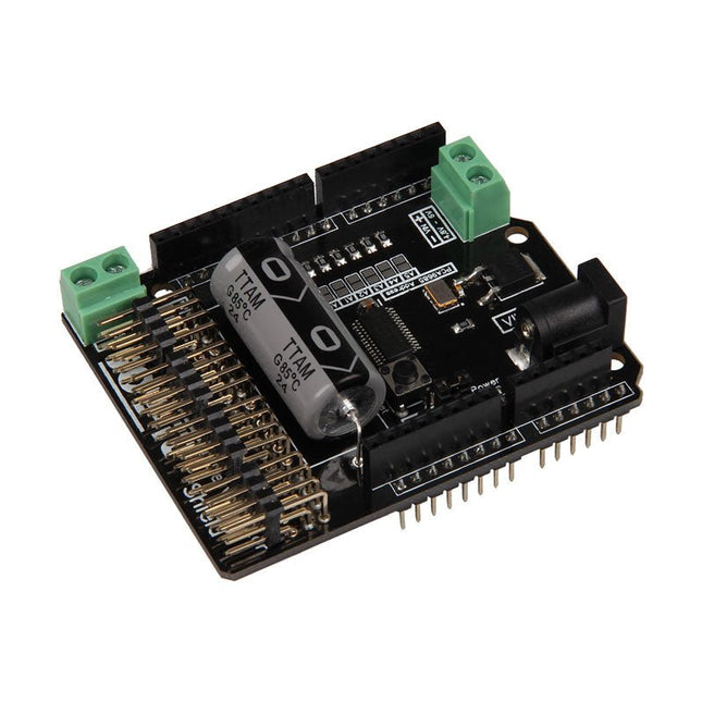
The Motorino board is an extension-board to control and use up to 16 PWM-controlled 5V-Servo-motors. The included clock generator ensures a very precise PWM signal and a very precise positioning. The board has 2 inputs for voltage from 4.8 V to 6 V which can be used for up to 11 A. With this input, a perfect power supply is always guaranteed and even bigger projects are no problem. The supply runs directly over the Motorino which provides a connection for voltage, ground and control. With the build in capacitor, the voltage is buffered which prevents a sudden voltage-drop at a high load. But there is also the possibility to connect another capacitor. The control and the programing can be done, as usual, with the Arduino. Manuals and code examples allows a quick introduction for beginners. Special features 16 Channels, own clock generator Input 1 Coaxial power connector 5.5 / 2.1 mm, 4.8-6 V / 5 A max Input 2 Screw-terminal, 4.8-6 V / 6 A max Communication 16 x PWM Compatible with Arduino Uno, Mega and may more microcontroller with Arduino compatible pinout Dimensions 69 x 24 x 56 mm Scope of supply Board, Manual, Retail package
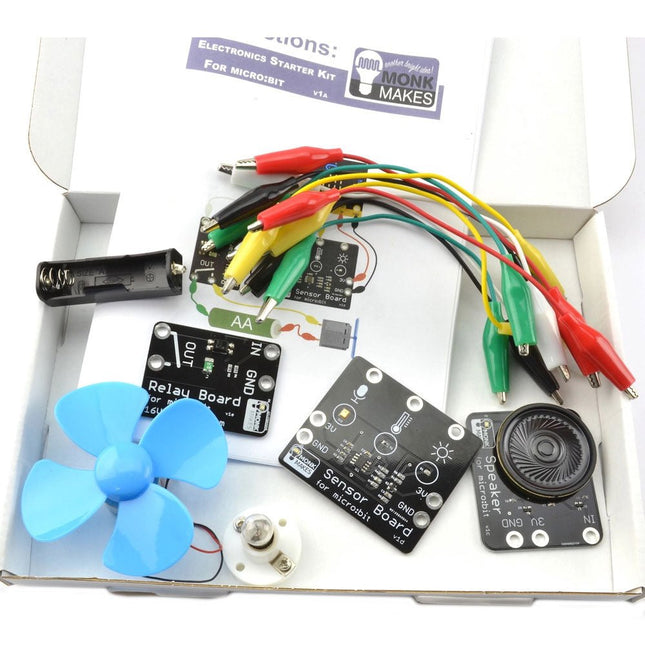
This kit contains everything needed to start learning about connecting electronics to the micro:bit in an accessible and easy manner. Everything is connected using the supplied alligator clips, so no soldering required.
Included
MonkMakes Speaker for micro:bit
MonkMakes Switch for micro:bit
MonkMakes Sensor Board for micro:bit
Set of alligator clip leads (10 leads)
Small motor with fan
Single AA battery box (battery not included)
Light bulb and holder
Booklet (A5)
Downloads
Instructions
Datasheet
Lesson Plans
This kit is based on ESP32 and LoRa. The ESP32 3.5" display is the console for the system, it receives the LoRa message from LoRa moisture sensors (support up to 8 sensors in the default firmware), and send control commands to LoRa 4-channel MOSFET (2 4-channel MOSFET supported, with totally 8 channels), to control the connected valves open/close, and thus to control the irrigation for multiple points.
Features
Ready to use: Firmware are pre-programmed for all the modules before shipping, the user can only power them up and set the ID to the console, and start to use. Suitable for none-programmers, in 3 minutes to create filed application.
With Lora wireless connection: The monitor & control range can be up to few kilometer, suitable for garden/small farm.
Soil moisture sensor with good corrosion resistance, can be used at least half an year with 2 AAA battery.
Easy to install: Compares to cheap solution with wires, which is hard to implement in files application, there the connection wires do not needed, the whole installation clean and easy; The valves can be connected Lora MOSFET easily.
Hardware & Software Open: To study Lora & FreeRTOS. The ESP32 display console/Lora Soil Moisture Sensor/LoRa MOSFE are all programmed with Arduino. For programmers/engineers, can development further more specialized application.
Based on ESP32, with WiFi connection, the console can also access to internet, the create much more applications including the moisture data updating to internet for remote monitor, and remote control with MQTT.
Included
1x ESP32 3.5' Display (without camera)
1x Lora Expansion for ESP32 Display
2x Lora Moisture Sensor
1x Lora 4-channel MOSFET
1x 12 V Power Supply
Water Pipe (5 m)
1x 1-input & 4-output Pipe Joint
Downloads
Instructable: Soil Monitoring & Irrigation with LoRa
GitHub
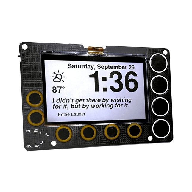
A low-power, open source, 2.7-inch IoT display powered by an ESP32-S2 module and featuring SHARP's Memory-in-Pixel (MiP) screen technology
The Newt is a battery-powered, always-on, wall-mountable display that can go online to retrieve weather, calendars, sports scores, to-do lists, quotes…really anything on the Internet! It is powered by an ESP32-S2 microcontroller that you can program with Arduino, CircuitPython, MicroPython, or ESP-IDF. It's perfect for makers:
Sharp’s Memory-in-Pixel (MiP) technology avoids the slow refresh times associated with E-Ink displays
A real-time clock (RTC) was added to support timers and alarms
The Newt was designed with battery operation in mind; every component on the board was chosen for its ability to operate at low power.
Newt was designed to operate 'untethered,' which means it can be mounted in places where a power cord would be inconvenient, for example a wall, refrigerator, mirror, or dry-erase board. With the optional stand, desks, shelves, and nightstands are also good options.
Newt is open source, and all design files and libraries are available for review, use, and modification. However, doing that is not required. Each Newt is delivered with working code with the following features:
Current weather details
Hourly and daily weather forecast
Alarm
Timer
Inspirational quotes
Air-quality forecast
Habit calendar
Pomodoro timer
Oblique Strategy cards
Only following the Wi-Fi provisioning instructions is needed to get started. No app downloads are required.
Specifications
Display
Sharp Memory LCD
Screen Size
2.7 inch
Resolution
240 x 400
Deep Sleep Current
30 uA
Refresh Rate
< 0.001 s
Periodic Screen Refresh Required
No
Input Buttons
10 capacitive pads, 1 push button
RTC included
Yes
Speaker included
Yes
Power Input
USB Type-C
Battery included
No
Programming Languages
Arduino, CircuitPython, ESP IDF, MicroPython
Dimensions
91 x 61 x 9 mm
Microcontroller
Espressif ESP32-S2-WROVER Module with 4 MB flash and 2 MB PSRAM
Wi-Fi capable
Supports Arduino, MicroPython, CircuitPython, and ESP-IDF
Deep sleep current as low as 25 μA
Display
2.7-inch, 240 x 400 pixel MiP LCD
Capable of delivering high-contrast, high-resolution, low-latency content with ultra-low power consumption
Reflective mode leverages ambient light to eliminate the need for a backlight
Time Keeping, Timers, and Alarms
Micro Crystal RV-3028-C7 RTC
Optimized for extreme low-power consumption (45 μA)
Able to simultaneously manage a periodic timer, a countdown timer, and an alarm
Hardware interrupt for timers and alarms
43 bytes of non-volatile user memory, 2 bytes of user RAM
Separate UNIX time counter
Buzzer
Speaker/buzzer with mini class-D amplifier on DAC output A0 can play tones or lo-fi audio clips
User Input
Power switch
Two programmable tactile buttons for Reset and Boot
10 capacitive touchpads
Power
Newt is designed to operate for one to two months between charges using a 500 mAH LiPo battery. The exact run time varies. (Heavy Wi-Fi use, in particular, will reduce battery charge more quickly.)
USB Type-C connector for programming, power, and charging
Low-quiescence voltage regulator (TOREX XC6220) that can output 1 A of current and operate as low as 8 μA.
JST connector for a Lithium-Ion battery
Battery-charging circuity (MCP73831)
Low-battery indicator (1 μA quiescence current)
Software
Newt hardware is compatible with open-source Arduino libraries for ESP32-S2, Adafruit GFX (fonts), Adafruit Sharp Memory Display (display writing), and RTC RV-3028-C7 (RTC)
Arduino libraries and sample programs are under development and will be available in our GitHub repository before launch
CircuitPython libraries and registration are on the roadmap, with the development of a CircuitPython library for the RV-3028 real-time clock as a key dependency
Included
Phambili Newt – Fully assembled with pre-loaded firmware
Laser-cut desktop stand
Mini-magnet feet
Required screws
Support & Documentation
Full instructions for use
GitHub: Arduino Library and Codebase
GitHub: Board schematics
Videos of prototypes or demos (build tracked on Hackaday)
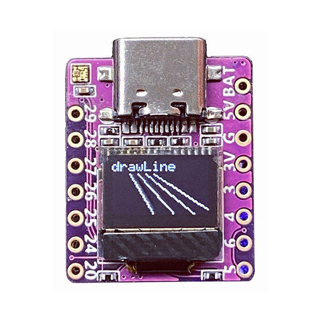
Arduino, MicroPython, and CircuitPython-compatible compact development board powered by Raspberry Pi RP2040
RP2040-0.42LCD is a high-performance development board with integrated 0.42" LCD (70x40 resolution) with flexible digital interfaces.
It incorporates Raspberry Pi's RP2040 microcontroller chip. The RP2040 features a dual-core Arm Cortex-M0+ processor clocked at 133 MHz with 264 KB internal SRAM and 2 MB flash storage.
Specifications
SoC
Raspberry Pi RP2040 dual-core Cortex-M0+ microcontroller at up to 125 MHz, with 264 KB SRAM
Storage
2 MB SPI flash
Display
0.42-inch OLED
USB
1x USB Type-C port for power and programming
Expansion
– Qwiic I²C connector– 7-pin and 8-pin headers with up to 11x GPIOs, 2x SPI, 2x I²C, 4x ADC, 1x UART, 5 V, 3.3 V, VBAT, GND
Misc
– Reset and Boot buttons– RGB LED, power LED
Power supply
– 5 V via USB-C port or Vin– VBAT pin for battery input– 3.3 V regulator with 500 mA peak output
Dimensions
23.5 x 18 mm
Weight
2.5 g
Downloads
GitHub
Here you will find all kinds of parts, components and accessories you will need in various projects, starting from simple wires, sensors and displays to already pre-assembled modules and kits.