The FRDM-MCXN947 is a compact and versatile development board designed for rapid prototyping with MCX N94 and N54 microcontrollers. It features industry-standard headers for easy access to the MCU's I/Os, integrated open-standard serial interfaces, external flash memory, and an onboard MCU-Link debugger.
Specifications
Microcontroller
MCX-N947 Dual Arm Cortex-M33 cores @ 150 MHz each with optimized performance efficiency, up to 2 MB dual-bank flash with optional full ECC RAM, External flash
Accelerators: Neural Processing Unit, PowerQuad, Smart DMA, etc.
Memory Expansion
*DNP Micro SD card socket
Connectivity
Ethernet Phy and connector
HS USB-C connectors
SPI/I²C/UART connector (PMOD/mikroBUS, DNP)
WiFi connector (PMOD/mikroBUS, DNP)
CAN-FD transceiver
Debug
On-board MCU-Link debugger with CMSIS-DAP
JTAG/SWD connector
Sensor
P3T1755 I³C/I²C Temp Sensor, Touch Pad
Expansion Options
Arduino Header (with FRDM expansion rows)
FRDM Header
FlexIO/LCD Header
SmartDMA/Camera Header
Pmod *DNP
mikroBUS
User Interface
RGB user LED, plus Reset, ISP, Wakeup buttons
Included
1x FRDM-MCXN947 Development Board
1x USB-C Cable
1x Quick Start Guide
Downloads
Datasheet
Block diagram
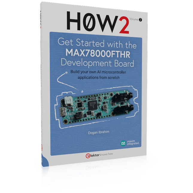
Build your own AI microcontroller applications from scratch
The MAX78000FTHR from Maxim Integrated is a small development board based on the MAX78000 MCU. The main usage of this board is in artificial intelligence applications (AI) which generally require large amounts of processing power and memory. It marries an Arm Cortex-M4 processor with a floating-point unit (FPU), convolutional neural network (CNN) accelerator, and RISC-V core into a single device. It is designed for ultra-low power consumption, making it ideal for many portable AI-based applications.
This book is project-based and aims to teach the basic features of the MAX78000FTHR. It demonstrates how it can be used in various classical and AI-based projects. Each project is described in detail and complete program listings are provided. Readers should be able to use the projects as they are, or modify them to suit their applications. This book covers the following features of the MAX78000FTHR microcontroller development board:
Onboard LEDs and buttons
External LEDs and buttons
Using analog-to-digital converters
I²C projects
SPI projects
UART projects
External interrupts and timer interrupts
Using the onboard microphone
Using the onboard camera
Convolutional Neural Network
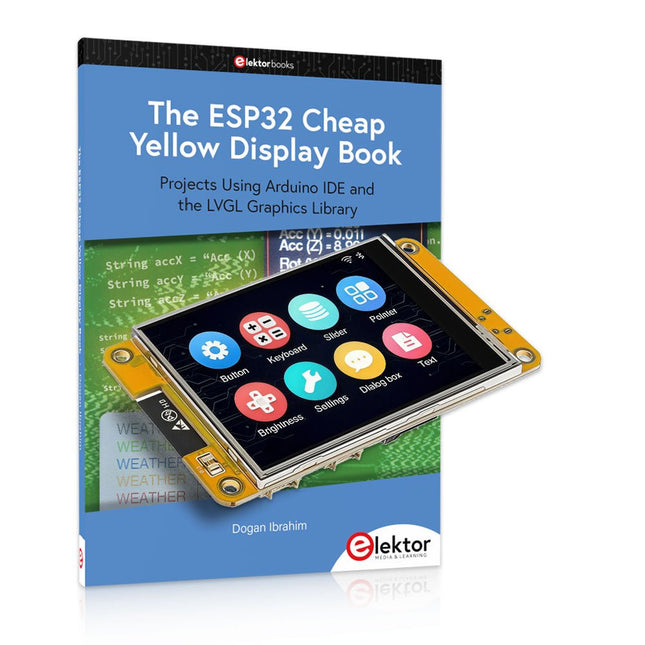
Over 40 Fully Tested ESP32 Projects Using Arduino IDE and the LVGL Graphics Library
This bundle includes the ESP32 Cheap Yellow Display (CYD) – a compact development board combining a standard ESP32 microcontroller with a 320x240 pixel TFT color display. The board also features multiple connectors for GPIO, serial communication (TX/RX), power, and ground. The built-in display is a major advantage, allowing users to create complex, graphics-based projects without the need for external LCDs or displays.
The accompanying book introduces the CYD board's hardware and on-board connectors in detail. It provides a range of beginner to intermediate-level projects developed using the popular Arduino IDE 2.0. Both basic graphics functions and the powerful LVGL graphics library are covered, with practical projects illustrating each approach.
All included projects have been fully tested and are ready to use. The book provides block diagrams, circuit schematics, complete code listings, and step-by-step explanations. With the LVGL library, readers can create modern, full-color graphical interfaces using widgets such as buttons, labels, sliders, calendars, keyboards, charts, tables, menus, animations, and more.
ESP32 Cheap Yellow Display Board
This development board (also known as "Cheap Yellow Display") is powered by the ESP-WROOM-32, a dual-core MCU with integrated Wi-Fi and Bluetooth capabilities. It operates at a main frequency of up to 240 MHz, with 520 KB SRAM, 448 KBROM, and a 4 MB Flash memory. The board features a 2.8-inch display with a resolution of 240x320 and resistive touch.
Furthermore, the board includes a backlight control circuit, touch control circuit, speaker drive circuit, photosensitive circuit, and RGB-LED control circuit. It also provides a TF card slot, serial interface, DHT11 temperature and humidity sensor interface, and additional IO ports.
The module supports development in Arduino IDE, ESP-IDE, MicroPython, and Mixly.
Applications
Image transmission for Smart Home device
Wireless monitoring
Smart agriculture
QR wireless recognition
Wireless positioning system signal
And other IoT applications
Specifications
Microcontroller
ESP-WROOM-32 (Dual-core MCU with integrated Wi-Fi and Bluetooth)
Frequency
Up to 240 MHz (computing power is up to 600 DMIPS)
SRAM
520 KB
ROM
448 KB
Flash
4 MB
Operating voltage
5 V
Power consumption
approx. 115 mA
Display
2.8-inch color TFT screen (240 x 320)
Touch
Resistive Touch
Driver chip
ILI9341
Dimensions
50 x 86 mm
Weight
50 g
Downloads
GitHub
Contents of the Bundle
The ESP32 Cheap Yellow Display Book (normal price: €35)
ESP32 Cheap Yellow Display Board (normal price: €25)
1x ESP32 Dev Board with 2.8" Display and acrylic Shell
1x Touch pen
1x Connector cable
1x USB cable
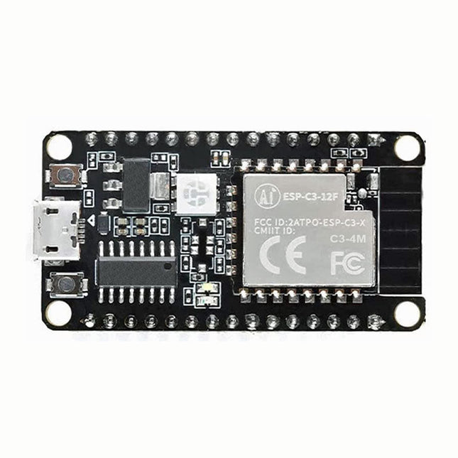
The ESP32-C3 chip has industry-leading low-power performance and radio frequency performance, and supports Wi-Fi IEEE802.11b/g/n protocol and BLE 5.0. The chip is equipped with a RISC-V 32-bit single-core processor with an operating frequency of up to 160 MHz. Support secondary development without using other microcontrollers or processors. The chip has built-in 400 KB SRAM, 384 KB ROM, 8 KB RTC SRAM, built-in 4 MB Flash also supports external Flash. The chip supports a variety of low power consumption working states, which can meet the power consumption requirements of various application scenarios. The chip's unique features such as fine clock gating function, dynamic voltage clock frequency adjustment function, and RF output power adjustable function can achieve the best balance between communication distance, communication rate and power consumption.
The ESP-C3-12F module provides a wealth of peripheral interfaces, including UART, PWM, SPI, I²S, I²C, ADC, temperature sensor and up to 15 GPIOs.
Features
Support Wi-Fi 802.11b/g/n, 1T1R mode data rate up to 150 Mbps
Support BLE5.0, does not support classic Bluetooth, rate support: 125 Kbps, 500 Kbps, 1 Mbps, 2 Mbps
RISC-V 32-bit single-core processor, supports a clock frequency of up to 160 MHz, has 400 KB SRAM, 384 KB ROM, 8 KB RTC SRAM
Support UART/PWM/GPIO/ADC/I²C/I²S interface, support temperature sensor, pulse counter
The development board has RGB three-in-one lamp beads, which is convenient for the second development of customers.
Support multiple sleep modes, deep sleep current is less than 5 uA
Serial port rate up to 5 Mbps
Support STA/AP/STA+AP mode and promiscuous mode
Support Smart Config (APP)/AirKiss (WeChat) of Android and iOS, one-click network configuration
Support serial port local upgrade and remote firmware upgrade (FOTA)
General AT commands can be used quickly
Support secondary development, integrated Windows and Linux development environment
About Flash configuration ESP-C3-12F uses the built-in 4 MB Flash of the chip by default, and supports the external Flash version of the chip.
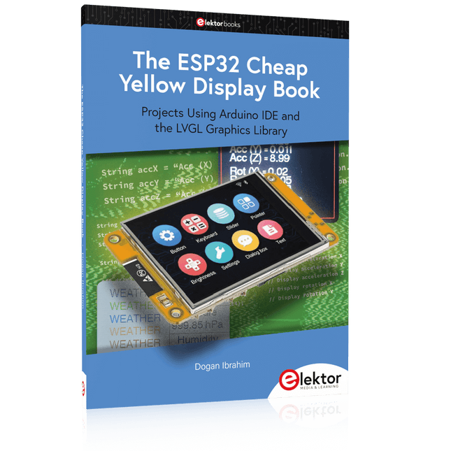
Projects Using Arduino IDE and the LVGL Graphics Library
The ESP32 is probably one of the most popular microcontrollers used by many people, including students, hobbyists, and professional engineers. Its low cost, coupled with rich features makes it a popular device to use in many projects. Recently, a board called the ESP32 Cheap Yellow Display (CYD for short) is available from its manufacturers. The board includes a standard ESP32 microcontroller together with a 320x240 pixel TFT display. Additionally, the board provides several connectors for interfaces such as GPIO, serial port (TX/RX), power and Ground. The inclusion of a TFT display is a real advantage as it enables users to design complex graphics-based projects without resorting to an external LCD or graphics displays.
The book describes the basic hardware of the ESP32 CYD board and provides details of its on-board connectors. Many basic, simple, and intermediate-level projects are given in the book based on the ESP32 CYD, using the highly popular Arduino IDE 2.0 integrated development environment. The use of both the basic graphics functions and the use of the popular LVGL graphics library are discussed in the book and projects are given that use both types of approaches.
All the projects given in the book have been tested and are working. The block diagram, circuit diagram, and the complete program listings and program descriptions of all the projects are given with explanations. Readers can use the LVGL graphics library to design highly popular eye-catching full-color graphics projects using widgets such as buttons, labels, calendars, keypads, keyboards, message boxes, spinboxes, sliders, charts, tables, menus, bars, switches, drop-down lists, animations, and many more widgets.
Build your own AI microcontroller applications from scratch
The MAX78000FTHR from Maxim Integrated is a small development board based on the MAX78000 MCU. The main usage of this board is in artificial intelligence applications (AI) which generally require large amounts of processing power and memory. It marries an Arm Cortex-M4 processor with a floating-point unit (FPU), convolutional neural network (CNN) accelerator, and RISC-V core into a single device. It is designed for ultra-low power consumption, making it ideal for many portable AI-based applications.
This book is project-based and aims to teach the basic features of the MAX78000FTHR. It demonstrates how it can be used in various classical and AI-based projects. Each project is described in detail and complete program listings are provided. Readers should be able to use the projects as they are, or modify them to suit their applications. This book covers the following features of the MAX78000FTHR microcontroller development board:
Onboard LEDs and buttons
External LEDs and buttons
Using analog-to-digital converters
I²C projects
SPI projects
UART projects
External interrupts and timer interrupts
Using the onboard microphone
Using the onboard camera
Convolutional Neural Network
The SparkFun RP2040 mikroBUS Development Board is a low-cost, high performance platform with flexible digital interfaces featuring the Raspberry Pi Foundation's RP2040 microcontroller. Besides the Thing Plus or Feather PTH pin layout, the board also includes a microSD card slot, 16 MB (128 Mbit) flash memory, a JST single cell battery connector (with a charging circuit and fuel gauge sensor), an addressable WS2812 RGB LED, JTAG PTH pins, four (4-40 screw) mounting holes, our signature Qwiic connectors, and a mikroBUS socket. The mikroBUS standard was developed by MikroElektronika. Similar to Qwiic and MicroMod interfaces, the mikroBUS socket provides a standardized connection for add-on Click boards to be attached to a development board and is comprised of a pair of 8-pin female headers with a standardized pin configuration. The pins consist of three groups of communications pins (SPI, UART and I²C), six additional pins (PWM, Interrupt, Analog input, Reset and Chip select), and two power groups (3.3 V and 5 V). The RP2040 is supported with both C/C++ and MicroPython cross-platform development environments, including easy access to runtime debugging. It has UF2 boot and floating-point routines baked into the chip. While the chip has a large amount of internal RAM, the board includes an additional 16 MB of external QSPI flash memory to store program code. The RP2040 contains two ARM Cortex-M0+ processors (up to 133 MHz) and features: 264 kB of embedded SRAM in six banks 6 dedicated IO for SPI Flash (supporting XIP) 30 multifunction GPIO: Dedicated hardware for commonly used peripherals Programmable IO for extended peripheral support Four 12-bit ADC channels with internal temperature sensor (up to 0.5 MSa/s) USB 1.1 Host/Device functionality Features (SparkFun RP2040 mikroBUS Dev. Board) Raspberry Pi Foundation's RP2040 microcontroller 18 Multifunctional GPIO Pins Four available 12-bit ADC channels with internal temperature sensor (500kSa/s) Up to eight 2-channel PWM Up to two UARTs Up to two I²C buses Up to two SPI buses Thing Plus (or Feather) Pin Layout: 28 PTH Pins USB-C Connector: USB 1.1 Host/Device functionality 2-pin JST Connector for a LiPo Battery (not included): 500mA charging circuit 4-pin JST Qwiic Connector LEDs:
PWR - Red 3.3V power indicator
CHG - Yellow battery charging indicator
25 - Blue status/test LED (GPIO 25)
WS2812 - Addressable RGB LED (GPIO 08) Buttons: Boot Reset JTAG PTH Pins 16MB QSPI Flash Memory µSD Card Slot mikroBUS Socket Dimensions: 3.7' x 1.2' Four Mounting Holes: 4-40 screw compatible Downloads Schematic Eagle Files Board Dimensions Hookup Guide Qwiic Info Page GitHub Hardware Repository
This carrier board combines a 2.4" TFT display, six addressable LEDs, onboard voltage regulator, a 6-pin IO connector, and microSD slot with the M.2 pin connector slot so that it can be used with compatible processor boards in our MicroMod ecosystem. We've also populated this carrier board with Atmel's ATtiny84 with 8kb of programmable flash. This little guy is pre-programmed to communicate with the processor over I²C to read button presses.
Features
M.2 MicroMod Connector
240 x 320 pixel, 2.4" TFT display
6 Addressable APA102 LEDs
Magnetic Buzzer
USB-C Connector
3.3 V 1 A Voltage Regulator
Qwiic Connector
Boot/Reset Buttons
RTC Backup Battery & Charge Circuit
microSD
Phillips #0 M2.5 x 3 mm screw included
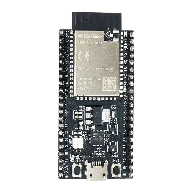
ESP32-S2-Saola-1R is a small-sized ESP32-S2 based development board. Most of the I/O pins are broken out to the pin headers on both sides for easy interfacing. Developers can either connect peripherals with jumper wires or mount ESP32-S2-Saola-1R on a breadboard.
ESP32-S2-Saola-1R is equipped with the ESP32-S2-WROVER module, a powerful, generic Wi-Fi MCU module that has a rich set of peripherals. It is an ideal choice for a wide variety of application scenarios relating to Internet of Things (IoT), wearable electronics and smart home. The board a PCB antenna and features a 4 MB external SPI flash and an additional 2 MB SPI Pseudo static RAM (PSRAM).
Features
MCU
ESP32-S2 embedded, Xtensa® single-core 32-bit LX7 microprocessor, up to 240 MHz
128 KB ROM
320 KB SRAM
16 KB SRAM in RTC
WiFi
802.11 b/g/n
Bit rate: 802.11n up to 150 Mbps
A-MPDU and A-MSDU aggregation
0.4 µs guard interval support
Center frequency range of operating channel: 2412 ~ 2484 MHz
Hardware
Interfaces: GPIO, SPI, LCD, UART, I²C, I²S, Camera interface, IR, pulse counter, LED PWM, TWAI (compatible with ISO 11898-1), USB OTG 1.1, ADC, DAC, touch sensor, temperature sensor
40 MHz crystal oscillator
4 MB SPI flash
Operating voltage/Power supply: 3.0 ~ 3.6 V
Operating temperature range: –40 ~ 85 °C
Dimensions: 18 × 31 × 3.3 mm
Applications
Generic Low-power IoT Sensor Hub
Generic Low-power IoT Data Loggers
Cameras for Video Streaming
Over-the-top (OTT) Devices
USB Devices
Speech Recognition
Image Recognition
Mesh Network
Home Automation
Smart Home Control Panel
Smart Building
Industrial Automation
Smart Agriculture
Audio Applications
Health Care Applications
Wi-Fi-enabled Toys
Wearable Electronics
Retail & Catering Applications
Smart POS Machines
Projects Using Arduino IDE and the LVGL Graphics Library
The ESP32 is probably one of the most popular microcontrollers used by many people, including students, hobbyists, and professional engineers. Its low cost, coupled with rich features makes it a popular device to use in many projects. Recently, a board called the ESP32 Cheap Yellow Display (CYD for short) is available from its manufacturers. The board includes a standard ESP32 microcontroller together with a 320x240 pixel TFT display. Additionally, the board provides several connectors for interfaces such as GPIO, serial port (TX/RX), power and Ground. The inclusion of a TFT display is a real advantage as it enables users to design complex graphics-based projects without resorting to an external LCD or graphics displays.
The book describes the basic hardware of the ESP32 CYD board and provides details of its on-board connectors. Many basic, simple, and intermediate-level projects are given in the book based on the ESP32 CYD, using the highly popular Arduino IDE 2.0 integrated development environment. The use of both the basic graphics functions and the use of the popular LVGL graphics library are discussed in the book and projects are given that use both types of approaches.
All the projects given in the book have been tested and are working. The block diagram, circuit diagram, and the complete program listings and program descriptions of all the projects are given with explanations. Readers can use the LVGL graphics library to design highly popular eye-catching full-color graphics projects using widgets such as buttons, labels, calendars, keypads, keyboards, message boxes, spinboxes, sliders, charts, tables, menus, bars, switches, drop-down lists, animations, and many more widgets.
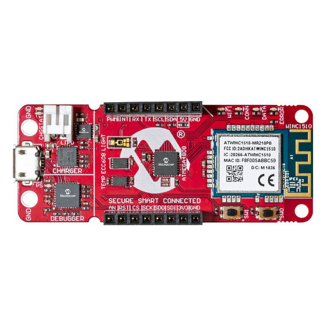
The AVR-IoT WA development board combines a powerful ATmega4808 AVR MCU, an ATECC608A CryptoAuthentication secure element IC and the fully certified ATWINC1510 Wi-Fi network controller – which provides the most simple and effective way to connect your embedded application to Amazon Web Services (AWS). The board also includes an on-board debugger, and requires no external hardware to program and debug the MCU.
Out of the box, the MCU comes preloaded with a firmware image that enables you to quickly connect and send data to the AWS platform using the on-board temperature and light sensors. Once you are ready to build your own custom design, you can easily generate code using the free software libraries in Atmel START or MPLAB Code Configurator (MCC).
The AVR-IoT WA board is supported by two award-winning Integrated Development Environments (IDEs) – Atmel Studio and Microchip MPLAB X IDE – giving you the freedom to innovate with your environment of choice.
Features
ATmega4808 microcontroller
Four user LED’s
Two mechanical buttons
mikroBUS header footprint
TEMT6000 Light sensor
MCP9808 Temperature sensor
ATECC608A CryptoAuthentication™ device
WINC1510 WiFi Module
On-board Debugger
Auto-ID for board identification in Atmel Studio and Microchip MPLAB X
One green board power and status LED
Programming and debugging
Virtual COM port (CDC)
Two DGI GPIO lines
USB and battery powered
Integrated Li-Ion/LiPo battery charger
Learn to program displays and GUIs with Python
This book is about Raspberry Pi 4 display projects. The book starts by explaining how to install the latest Raspbian operating system on an SD card, and how to configure and use the GPIO ports.
The core of the book explains the following topics in simple terms with fully tested and working example projects:
Simple LED projects
Bar graph LED projects
Matrix LED projects
Bitmap LED projects
LED strips
LCDs
OLED displays
E-paper displays
TFT displays
7-inch touch screen
GUI Programming with Tkinder
One unique feature of this book is that it covers almost all types of display that readers will need to use in their Raspberry Pi based projects. The operation of each project is fully given, including block diagrams, circuit diagrams, and commented full program listings. It is therefore an easy task to convert the given projects to run on other popular platforms, such as Arduino or PIC microcontrollers.
Python program listings of all Raspberry Pi projects developed in this book are available for download at Elektor.com. Readers can use these programs in their projects. Alternatively, they can modify the programs to suit their applications.