


Here you will find all kinds of parts, components and accessories you will need in various projects, starting from simple wires, sensors and displays to already pre-assembled modules and kits.
Components
-

SunFounder Universal Maker Sensor Kit (for Raspberry Pi, Pico W, Arduino, ESP32)
Discover endless creativity with the Universal Maker Sensor Kit, designed for use with Raspberry Pi, Pico W, Arduino, and ESP32. This versatile kit offers compatibility across popular development platforms, including Arduino Uno R4 Minima/WiFi, Uno R3, Mega 2560, Raspberry Pi 5, 4, 3B+, 3B, Zero, Pico W, and ESP32. Featuring over 35 sensors, actuators, and displays, it's perfect for projects ranging from environmental monitoring and smart home automation to robotics and interactive gaming. Step-by-step tutorials in C/C++, Python, and MicroPython guide beginners and experienced makers alike through 169 exciting projects. Features Wide Compatibility: Fully supports Arduino (Uno R3, Uno R4 Minima/WiFi, Mega 2560), Raspberry Pi (5, 4, 3B+, 3B, Zero, Pico W), and ESP32, enabling extensive flexibility across numerous development platforms. Includes instructions for building 169 projects. Comprehensive Components: Features more than 35 sensors, actuators, and display modules suitable for diverse projects such as environmental monitoring, smart home automation, robotics, and interactive game controllers. Detailed Tutorials: Provides clear, step-by-step tutorials covering Arduino, Raspberry Pi, Pico W, ESP32, and each included component. Tutorials are available in C/C++, Python, and MicroPython, catering effectively to both beginners and experienced makers. Suitable for All Skill Levels: Offers structured projects designed to guide users seamlessly from beginner to advanced proficiency in electronics and programming, enhancing creativity and technical expertise. Included Breadboard Button Module Capacitive Soil Moisture Module Flame Sensor Module Gas/Smoke Sensor Module (MQ2) Gyroscope & Accelerometer Module (MPU6050) Hall Sensor Module Infrared Speed Sensor Module IR Obstacle Avoidance Sensor Module Joystick Module PCF8591 ADC DAC Converter Module Photoresistor Module PIR Motion Module (HC-SR501) Potentiometer Module Pulse Oximeter and Heart Rate Sensor Module (MAX30102) Raindrop Detection Module Real Time Clock Module (DS1302) Rotary Encoder Module Temperature Sensor Module (DS18B20) Temperature and Humidity Sensor Module (DHT11) Temperature, Humidity & Pressure Sensor (BMP280) Time of Flight Micro-LIDAR Distance Sensor (VL53L0X) Touch Sensor Module Ultrasonic Sensor Module (HC-SR04) Vibration Sensor Module (SW-420) Water Level Sensor Module I²C LCD 1602 OLED Display Module (SSD1306) RGB LED Module Traffic Light Module 5 V Relay Module Centrifugal Pump L9110 Motor Driver Module Passive Buzzer Module Servo Motor (SG90) TT Motor ESP8266 Module JDY-31 Bluetooth Module Power Supply Module Documentation Online Tutorial
-

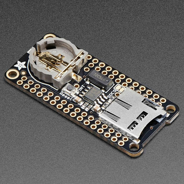
Adafruit Adafruit Adalogger FeatherWing (RTC + SD Add-on)
This FeatherWing will make it easy to add data logging to any Feather Board you might have. You get both an I²C real-time clock (PCF8523) with 32 KHz crystal and battery backup, and a microSD socket that connects to the SPI port pins (+ extra pin for CS). Note: FeatherWing doesn't come with a microSD card. A CR1220 coin cell is required to use the RTC battery-backup capabilities. If you're not using the RTC part of the FeatherWing, a battery is not required. To talk to the microSD card socket Arduino's default SD library is recommended. Some light soldering is required to attach the headers onto the Wing. Pinouts Power pins On the bottom row, the 3.3 V (second from left) and GND (fourth from left) pin are used to power the SD card and RTC (to take a load off the coin cell battery when main power is available) RTC & I²C Pins In the top right SDA (rightmost) and SCL (to the left of SDA) are used to talk to the RTC chip. SCL - I²C clock pin to connect to your microcontroller's I2C clock line. This pin has a 10 kΩ pull-up resistor to 3.3 V SDA - I²C data pin to connect to your microcontroller's I2C data line. This pin has a 10 kΩ pull-up resistor to 3.3 V There's also a breakout for INT which is the output pin from the RTC. It can be used as an interrupt output or it could also be used to generate a square wave. Note that this pin is an open drain - you must enable the internal pull-up on whatever digital pin it is connected to. SD & SPI Pins Starting from the left you've got SPI Clock (SCK) - output from feather to wing SPI Master Out Slave In (MOSI) - output from feather to wing SPI Master In Slave Out (MISO) - input from wing to feather These pins are in the same location on every Feather. They are used for communicating with the SD card. When the SD card is not inserted, these pins are completely free.
-

Velleman Whadda Electronic Dice
This electronic dice with 7 red LEDs rolls when the push button is released and works with a 9 V battery (not included). Downloads Manual
€ 6,50
-

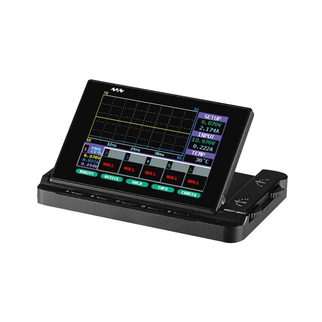
Miniware Miniware MDP-M01 Smart Digital Monitor
MDP-M01 is a display control module equipped with a 2.8-inch TFT display screen, the screen can be turned 90 degrees, which is convenient for users to view data and waveform. MDP-M01 can realize online display and control with MDP-P906 mini digital power supply modules and other modules of MDP system through 2.4 GHz wireless communication, and can control up to 6 sub-modules at the same time. Specifications Screen size 2.8" TFT Screen resolution 240 x 320 Power Micro USB power input, or taking power from sub-module via dedicated power cable Input DC 5 V/0.3 A Other functions Can control up to 6 sub-modulesUpgrade firmware through Micro USB Dimensions 107 x 66 x 13.6 mm Weight 133 g Included 1x MDP-M01 Smart Digital Monitor 1x Cable (2.5 mm jack to Micro USB) Downloads User Manual v3.4 Firmware v1.32
€ 79,00
-

Velleman Whadda 3D Xmas Tree Kit
The Whadda 3D Xmas Tree Kit is aimed at hobbyists and beginners who are interested in soldering and electronics. With this DIY kit, you can build a festive LED Christmas tree. Features 16 flashing red LEDs Extra green and yellow LEDs provided to customise your tree Can be hung on and fed through wires Will operate on 12 V DC (e.g. in cars) Specifications Low power consumption 8 mA Power supply 9 V battery operation (not included) Dimensions 102 x 88 x 80 mm Weight 65 g Downloads Manual
€ 10,95