Bestsellers
-
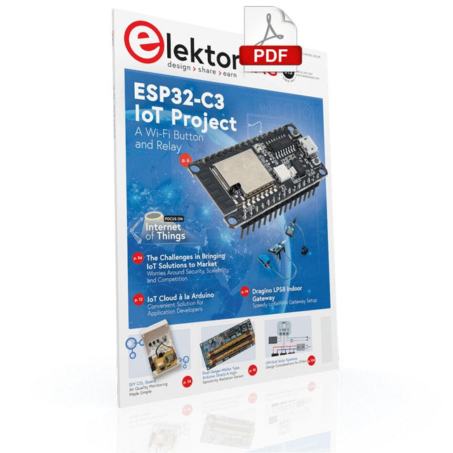
Elektor Digital Elektor May/June 2022 (PDF)
Your First Steps with an ESP32-C3 and the IoTA Wi-Fi Button and Relay IoT Cloud a la Arduino Dual Geiger-Müller Tube Arduino ShieldA High Sensitivity, Very Low-Power Radiation Sensor CO2 GuardA DIY Approach to Monitoring Air Quality MonkMakes Air Quality Kit for Raspberry PiMeasures Temperature and eCO2 Starting Out in ElectronicsWelcome to the Diode Tips & Tricks for Testing ComponentsNo Expensive Equipment Required Reducing the Power Consumption of Your Mole RepellerAn ATtiny13 Replaces a 555 Light Switch DeLuxA Solution for High-Precision Light-Controlled Switching The Challenges in Bringing IoT Solutions to MarketWorries Around Security, Scalability, and Competition Infographics 5-6/2022 Preferably Wired After AllTips for Developing a 1 Gbit/s Interface in an Industrial Environment Bringing Real-Time Object Detection to MCUs with Edge Impulse FOMO Traveling-Wave TubesPeculiar Parts, the Series Narrowband Internet of ThingsStandards, Coverage, Agreements, and Modules Dragino LPS8 Indoor GatewaySpeedy LoRaWAN Gateway Setup Explore ATtiny Microcontrollers Using C and Assembly LanguageSample Chapter: ATtiny I/O Ports Err-lectronicsCorrections, Updates and Readers’ Letters LoRa GPS Tracker UpdateReceive and Show Location Using a Raspberry Pi Circuit Simulation with TINA Design Suite & TINACloudSample Chapter: Sinusoidal Oscillators From Life’s ExperienceAssembly Line Work The WinUI Graphics Framework for Windows AppsA Small Demo Application GUIs with PythonWorst GUI of the world Off-Grid Solar SystemsElectrical Energy Independent of the Mains Grid The 10-Year SmartphoneRenew Your Expectations HexadokuThe Original Elektorized Sudoku
€ 7,50
-

Elektor Digital Elektor March/April 2025 (PDF) EN
Elektor GREEN and GOLD members can download their digital edition here. Not a member yet? Click here. The RISC-V Open-Source Processor Architecture16 Boards and MCUs You Should Know An FPGA-Based Audio Player with Equalizer (1)Mixing Digital Audio with an Arduino MKR Vidor 4000 Laser Head for Pico-Based Sand ClockDrawing with Light Enter the STM32 Edge AI Contest A Multi-Sensor Environmental Monitoring System for PlantsWireless Measurement of Water Supply and Light Conditions Maixduino AI-Powered Automatic DoormanFace Detection with a Camera Embedded Electronics 2024AI Is Set to Redefine the Industry Charge-Based In-Memory Compute at EnCharge AI AI Inferencing at 10 Times Lower Power and 20 Fold Lower Cost Click Board Helps Develop and Train ML Models for Vibration Analysis The Elektor Mini-WheelieA Self-Balancing Robot Kit MCU, I See YouMCUViewer Open-Source Multiplatform Debugging Tool USB 2.0 IsolatorElectrically Isolated Connections for USB Devices Intervention Before DamagePredictive Maintenance in Practice SPoE – Electromagnetic CompatibilitySingle-Pair with Power-Over-Ethernet Through the Eyes of EMC Color TV: A Wonder of Its TimeCreating a New World ECG Graph MonitoringAn Implementation with Hexabitz Modules and an STM32CubeMonitor The Battle for AI at the Edge HaLow Hits Record 16-km Wi-Fi Distance at 900 MHz First CHERI RISC-V Embedded Chip and Early Access Programme Third-Generation Wildfire Detection Uses Satellite Links From Life’s ExperienceChoice Overload Starting Out in Electronics……Continues Filtering and Controls Tone Quasi-Analog ClockworkA Remake of an Elektor Classic A Modular Approach to Sensor TestingThe ESP32-S3-Based Sensor Evaluation Board 2025: An AI OdysseyThe Rise of Foundation Models and Their Role in Democratizing AI Raspberry Pi Standalone MIDI Synthesizer (1)Preparing a Platform for Some Edge AI Experiments Err-lectronicsCorrections, Updates, and Readers’ Letters Universal AI RISC-V Processor Does It All — CPU, GPU, DSP, FPGA CEO Interview: Ventiva’s Thin and Cool Tech Dual-Core Programming with a Raspberry Pi PicoVenture Into the World of Parallel Programming
€ 7,50
-
Elektor Digital ARM Microcontroller Projects (E-book)
It is becoming important for microcontroller users to quickly learn and adapt to new technologies and architecture used in high performance 32-bit microcontrollers. Many manufacturers now offer 32-bit microcontrollers as general purpose processors in embedded applications. ARM provide 32 and 64-bit processors mainly for embedded applications. These days, the majority of mobile devices including mobile phones, tablets, and GPS receivers are based on ARM technology. The low cost, low power consumption, and high performance of ARM processors makes them ideal for use in complex communication and mixed signal applications. This book makes use of the ARM Cortex-M family of processors in easy-to-follow, practical projects. It gives a detailed introduction to the architecture of the Cortex-M family. Examples of popular hardware and software development kits are described. The architecture of the highly popular ARM Cortex-M processor STM32F107VCT6 is described at a high level, taking into consideration its clock mechanisms, general input/output ports, interrupt sources, ADC and DAC converters, timer facilities, and more. The information provided here should act as a basis for most readers to start using and programming the STM32F107VCT6 microcontroller together with a development kit. Furthermore, the use of the mikroC Pro for ARM integrated development environment (IDE) has been described in detail. This IDE includes everything required to create a project; namely an editor, compiler, simulator, debugger, and device programmer. Although the book is based on the STM32F107VCT6 microcontroller, readers should not find it difficult to follow the projects using other ARM processor family members.
€ 34,95
Members: € 31,46
-
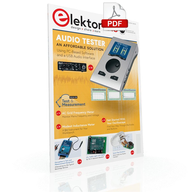
Elektor Digital Elektor July/August 2022 (PDF)
Measuring Does Not Have to be Expensive Low-Cost Audio TesterUsing PC-Based Software and a USB Audio Interface AC Grid Frequency MeterMonitor Mains Frequency and Voltage A Modest Inductance MeterAn Affordable Solution for Your Workbench Acoustic Wave HoveringA Look at the Makerfabs Acoustic Levitation Kit Starting Out in ElectronicsRectifiers E-FFWD: Looking Ahead Again! Get Started With Your OscilloscopeFind Your Way Through the Knobs and Buttons Raspberry Pi Pico Makes an MSF-SDRDecode a Time Signal with a Pi Pico SDR Moisture Sensors for Watering SystemsAutomatic Watering Disruption in Test and Measurement EquipmentInnovation from the Smaller Players Infographics 7-8/2022 Inspiration, That’s What It’s All AboutInterview with Entrepreneur Walter Arkesteijn, InnoFaith Beauty Sciences Minimizing EMC Interference from Storage Chokes GUIs with Python (Part 5)Tic-Tac-Toe Reed RelaysPeculiar Parts, the series Simple Analog ESR Meter With Moving-Coil Meter Precision Sigfox CO2 Traffic LightNo Wi-Fi Network Needed! Women in Tech“It's All About Merit Until Merit Has Tits” Low-Budget Tablet Oscilloscope ADS1013DGood Value for Money? Smart Plug TeardownWhich Ones Are Hacker-Friendly? Skin Impedance and Skin CapacitanceSmall Experiments From Life’s ExperienceNo Local Business Pokit Meter ReviewA Swiss army knife of test gear HexadokuThe Original Elektorized Sudoku
€ 7,50
-
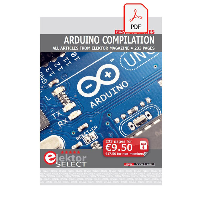
Elektor Digital Arduino Compilation (EN) | E-book
This 233-page e-book is packed with Arduino ideas, explanations, tips, diagrams, programs, PCB layouts, and more – enough to provide days of informative, inspiring, and stimulating reading pleasure! The PDF document includes a table of contents with links to the individual projects, allowing you to easily navigate to the sections you’re most interested in. This way, you can quickly and effortlessly switch between projects and find exactly what you’re looking for.
€ 9,95
Members: € 8,96
-
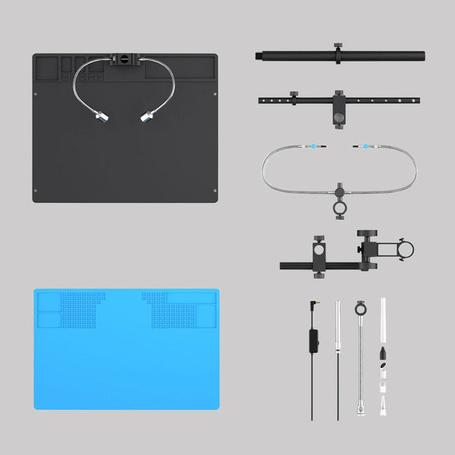
Andonstar Andonstar Max Station Upgrade Set for AD409 Models
Upgrade your Andonstar AD409, AD409 Pro, or AD409 Pro-ES to the Max model with this enhancement kit. The newly designed, oversized Max station provides ample workspace, making it perfect for larger projects and ideal for professional soldering tasks. Included 1x Stand with 2 LEDs 1x Repair mat 1x Beam 1x Column 1x Tool holder 1x Soldering Helping Hands
€ 60,00
-
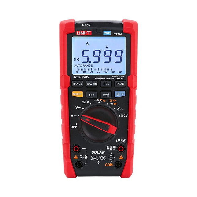
Uni-Trend UNI-T UT196 True RMS Solar Multimeter
The UT196 True RMS solar multimeter is an ideal tool for solar power system maintenance. This rugged meter is designed for technicians who work in rugged outdoor environments. UT196 can measure up to 1700 V DC and 1500 V AC voltages, and 3000 A AC current with an external current clamp sensor. This solar meter offers IP65 protection and able to withstand 2 m drop as well. The UT196 solar multimeter is designed with 1700 V DC, 1500 Vrms AC overload protection and tested for safe usage in CAT III 1000 V, CAT IV 600 V environments. Features True RMS Measure up to 1700 V DC and 1500 V AC for high voltage applications e.g. solar array, wind IP65 protection CAT III 1000V, CAT IV 600 V Analog bar Frequency response: 45 Hz~1 kHz Low-pass filter function Low impedance mode Built-in flashlight, bright backlight and visual alarm Applications High DC voltage measurement Output voltage and frequency measurement Voltage and frequency measurement Current and frequency measurement Specifications Range UT196 DC voltage (V) 1700 V ±0.2% +5 AC voltage (V) 1500 V ±0.8% +3 Frequency (Hz) 1 MHz ±0.08% +4 Resistance (Ω) 60 MΩ ±0.8% +2 Capacitance (F) 60 mF ±1.9% +5 Power 9 V battery Dimensions 195 x 95 x 58 mm Included UT196 Solar Multimeter Battery Test leads Downloads Datasheet Manual
€ 129,63
-

OWON OWON HDS2202s 2-ch Oscilloscope (200 MHz) + Multimeter + Signal Generator
The OWON HDS2202s is a portable 3-in-1 multifunctional tester, which can be used as a 2-ch oscilloscope with a bandwidth of 200 MHz, multimeter and signal generator. It features a high-contrast 3.5-inch color display suitable for outdoor facility maintenance, rapid on-site measurement, automobile maintenance, power detection. etc. Features Oscilloscope + multimeter + waveform generator, multifunction in one 3.5-inch high-resolution, high-contrast color LCD display, suitable for outdoor use 18650 lithium battery, can work continuously for 3-6 hours USB Type-C interface, support power bank, support PC software connection Self-calibration function SCPI supported, facilitate secondary development Specifications Bandwidth 200 MHz Channels 2-ch Oscilloscope + 1-ch Generator Sample Rate 1 GSa/s Acquisition Model Normal, Peak detect Record Length 8K Display 3.5-inch LCD Waveform Refresh Rate 10,000 wfrms/s Input Coupling DC, AC, and Ground Input Impedance 1 MΩ ±2%, in parallel with 16pF ±10pF Probe Attenuation Factors 1X,10X,100X,1000X,10000X Max. input Voltage 400 V (DC+AC, PK-PK, 1MΩ input impedance) (10:1 probe attenuation) Bandwidth Limit (typical) 20 MHz Horizontal Scale 2ns/div - 1000s/div, step by 1 - 2 - 5 Vertical Sensitivity 10mV/div - 10V/div Vertical Resolution 8 bits Trigger Type Edge Trigger Modes Auto, Normal, single Automatic Measurement Frequency, Period, Amplitude, Max, Min, Mean, PK-PK Cursor Measurement ΔV, ΔT, ΔT&ΔV between cursors Communication Interface USB Type-C Multimeter Specifications Max. Resolution 20,000 counts Testing Mode Voltage, Current, Resistance, Capacitance, Diode, and Continuity test Input Impedance 10 MΩ Max Input Voltage AC 750 V, DC 1000 V Max Input Current DC: 10 A, AC: 10 A Diode 0-2 V Waveform Generator Specifications Frequency Output Sine 0.1 Hz - 25 MHz Square 0.1 Hz - 5MHz Ramp 0.1 Hz - 1 MHz Pulse 0.1 Hz - 5 MHz Arbitrary 0.1 Hz - 5 MHz Sampling Rate 125 MSa/s Channel 1-ch Amplitude Range (high impedance) 20 mVpp - 5 Vpp Waveform Length 8K Vertical Resolution 14 bits Output Impedance 50Ω Included 1x OWON HDS2202s 1x Power adapter 1x USB cable 1x Passive probes 2x Crocodile clip cable 1x Set of multimeter probes (one red and one black) 1x User manual 1x Probe correction adjustment knife Downloads User Manual Specifications SCPI Protocol Quick Guide Software
€ 242,00
-

Elektor Digital Artificial Intelligence (E-book)
23 projects to bring your microcontroller to life! This book contains 23 special and exciting artificial intelligence machine-learning projects, for microcontroller and PC. Learn how to set up a neural network in a microcontroller, and how to make the network self-learning. Discover how you can breed robots, and how changing a fitness function results in a totally different behavior. Find out how a PC program exposes your weak spots in a game, and ruthlessly exploits them. Build a free-will robot, or have one clean your floor! Example projects from the book: A microcontroller that learns what your favourite color is. A robot wandering about the house looking for someone to play with. A bred robot program that is incapable of crossing a black line. A microcontroller that learns how to play a game until You just can't win anymore. A PC that programs a microcontroller all by itself. Complete with free software that you can download containing: All source code for the microcontroller. All sources of compiled PC programs (MS Windows). JAL programming language, with special editor and extension libraries. Robot breed program. Plus a support webpage with links, errata and FAQ. Several artificial intelligence techniques are discussed and used in projects such as expert system, neural network, subsumption, emerging behavior, genetic algorithm, cellular automata and roulette brains. Every project has clear instructions and pictures so you can start immediately. Suggestions and literature links allow you to go way beyond the scope of the book. Even after you have built all the projects contained within, this book will remain a valuable reference guide to keep next to your PC. A unique book for anyone with an interest in artificial intelligence and machine learning.
€ 29,95
Members: € 26,96
-

Siglent Siglent SDS1104X-U 4-ch Oscilloscope (100 MHz)
The SDS1000X-U series employs SPO (Super Phosphor Oscilloscope) technology that provides excellent signal fidelity and performance. It comes with an innovative digital trigger system with high sensitivity and low jitter, and a waveform capture rate of 400,000 frames/sec (sequence mode). The SDS1000X U also employs a 256 level intensity grading display function and a color temperature display mode not found in other models in this class. Another powerful addition is the new 128 k point FFT math function that gives the SDS1000X-U a very high-frequency resolution when observing signal spectra. SDS1000X-U also supports searching and navigating. The features and performance of SIGLENT’s new SDS1000X-U cannot be matched anywhere else in this price class. Features 100 MHz bandwidth Real-time sampling rate up to 1 GSa/s The newest generation of SPO technology Waveform capture rates up to 100,000 wfm/s (normal mode) and 400,000 wfm/s (sequence mode) Supports 256-level intensity grading and color temperature display modes Record length up to 14 Mpts Digital trigger system Intelligent trigger: Edge, Slope, Pulse Width, Window, Runt, Interval, Time out (Dropout), Pattern Serial bus triggering and decoding (Standard), supports protocols I²C, SPI, UART, CAN, LIN Video trigger, supports HDTV 10 types of one-button shortcuts, supports Auto Setup, Default, Cursors, Measure, Roll, History, Display/Persist, Clear Sweep, Zoom and Print Segmented acquisition (Sequence) mode, divides the maximum record length into multiple segments (up to 80,000), according to trigger conditions set by the user Automatic measurement function for 38 parameters as well as Measurement Statistics, Zoom, Gating, Math, History and Reference functions History waveform record (History) function (maximum recorded waveform length is 80,000 frames) 128 k pts FFT, supports Peaks and Markers Math functions (FFT, addition, subtraction, multiplication, division, integration, differential, square root) Large 7 inch TFT LCD display with 800 x 480 resolution Downloads Datasheet Manual Programming Guide
€ 401,00
-

Elektor Digital Arduino Uno – 45 Projects for Beginners and Experts (E-book)
This book covers a series of exciting and fun projects for the Arduino, such as a silent alarm, people sensor, light sensor, motor control, internet and wireless control (using a radio link). Contrary to many free projects on the internet all projects in this book have been extensively tested and are guaranteed to work! You can use it as a projects book and build more than 45 projects for your own use. The clear explanations, schematics, and pictures of each project make this a fun activity. The pictures are taken of a working project, so you know for sure that they are correct. You can combine the projects in this book to make your own projects. To facilitate this, clear explanations are provided on how the project works and why it has been designed the way it has That way you will learn a lot about the project and the parts used, knowledge that you can use in your own projects. Apart from that, the book can be used as a reference guide. Using the index, you can easily locate projects that serve as examples for the C++ commands and Arduino functionality. Even after you’ve built all the projects in this book, it will still be a valuable reference guide to keep next to your PC.
€ 29,95
Members: € 26,96
-
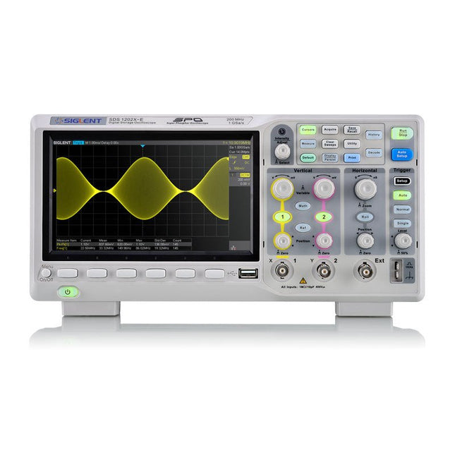
Siglent Siglent SDS1202X-E 2-ch Oscilloscope (200 MHz)
SIGLENT’s SDS1000X-E Series Super Phosphor Oscilloscope is available in one bandwidth, 200 MHz. It has a maximum sample rate of 1 GSa/s and a standard record length of 1 Mpts. For ease-of-use, the most commonly used functions can be accessed with its user-friendly front panel design. The SDS1000X-E series employs a new generation of SPO (Super Phosphor Oscilloscope) technology that provides excellent signal fidelity and performance. The system noise is also lower than similar products in the industry. It comes with a minimum vertical input range of 500 uV/div, an innovative digital trigger system with high sensitivity and low jitter, and a waveform capture rate of 400,000 frames/ sec (sequence mode). The SDS1000X-E also employs a 256-level intensity grading display function and a color temperature display mode not found in other models in this class. Siglent’s latest oscilloscopes offering supportsmultiple powerful triggering modes including serial bus triggering. Decoding is standard configuration including IIC,SPI,UART,CAN,LIN. History waveform recording and sequential triggering enable extended waveform recording and analysis. Another powerful addition is the new 1 million points FFT math function that gives the SDS1000X-E very high frequency resolution when observing signal spectra. The new design also includes a hardware co-processor that delivers measurements quickly and accurately. The features and performance of Siglent’s new SDS1000X-E cannot be matched anywhere else in this price class. Specifications Bandwidth 200 MHz Channels 2CH+1EXT Real time sampling rate 1 GSa/s Memory depth 7 Mpts/CH (Dual-Channel); 14 Mpts/CH (Single-Channel) Waveform Capture Rate (Max.) 100,000 wfm/s (normal mode); 400,000 wfm/s (sequence mode) Serial Trigger (Standard) I²C, SPI, UART/RS232, CAN, LIN Decode Type (Standard) I²C, SPI, UART/RS232, CAN, LIN Trigger Type Edge, Slope, Pulse Width, Window, Runt, Interval, Dropout, Pattern, Video Probe (Std) 2 pcs passive probe PP215 Display 7 inch TFT-LCD (800x480) Weight Without package 2.5 kg; with package 3.5 kg Downloads Datasheet Manual Programming Guide
€ 401,99
-
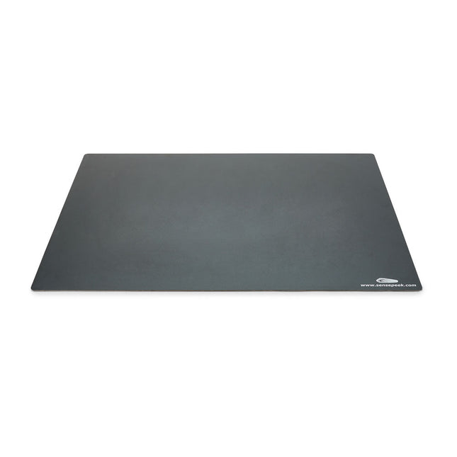
Sensepeek Sensepeek 4021 Insulated XL Base Plate
Components are both shrinking and getting increasingly finer pitch year after year but your PCBs might have grown in size or the number of interconnected PCBs or the number of handsfree PCBite probes needed to test your design may have increased making it crowded on our other smaller base plates. Features With a size of 297 x 420 mm (DIN A3) the extra large baseplate has room for most PCBs and many handsfree PCBite probes for those measurements sessions where more channels than available is needed. So if you are looking for more space, extra protection or just want to clean up your work surface then this accessory is a perfect match. Designed to be used with Sensepeeks magnetic PCBite line of products including PCB holders, hands free probes and magnifier. Included 1x XL base plate (DIN A3) with pre-fitted insulation cover
€ 71,39
-
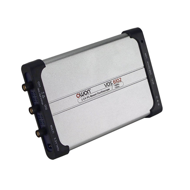
OWON OWON VDS6102A 2-ch USB Oscilloscope (100 MHz)
The OWON VDS6000 Series PC Oscilloscope combines powerful performance with a sleek, ultra-thin design. With 100 MHz bandwidth, 1 GSa/s real-time sampling, and up to 14-bit resolution, it delivers highly accurate measurements. The built-in 5 MHz function generator, USB-C power supply, and optional WiFi connectivity make it incredibly versatile. Compatible with Windows, Linux, Android, and iOS, the VDS6000 is perfect for labs, fieldwork, and remote diagnostics – compact, flexible, and ready for any challenge. Features Bandwidth: 100 MHz Vertical resolution: 14 bits Rise time: ≤3.5 ns Memory: 10 Mpts Number of channels: 2 channels + 1 channel function generator Horizontal scale: 5ns - 100s/div Sample rate: Max. 1 GSa/s Maximum voltage: 40 V (peak - peak) Automatic measurements: Vpp, Vavg, Vamp, Vrms, Freq, Period, Vmax, Vmin, Vtop, Vbase, Overshoot, Preshoot, Rise Time, Connectivity: USB-C, LAN, Wifi (optional) Fall Time, Delay A→B↑, Delay A→B↓, +Width, -Width, +Duty, -Duty Bandwidth: 5 MHz Sample rate: 25 MSa/s Standard waveforms: Sine (0.1 Hz - 5 MHz), Square (0.1 Hz - 200 kHz), Ramp (1 Hz - 10 kHz), Pulse (1 Hz - 10 kHz) Resolution: 10 bits DC offset range (AC + DC): ±2.5 V Amplitude range: 10 mVpp - 5 Vpp Dimensions: 190 x 120 x 18 mm Weight: 380 g Downloads Manual Quick Guide PC Software MacOS Software
€ 330,00
-

Elektor Digital The EAGLE Companion (E-book)
EAGLE – the “Easily Applicable Graphical Layout Editor“ is a professional-grade CAD (computer aided design) software package for the design and drafting of electronic schematics as well as the design and fabrication of printed circuit boards (PCBs). This Advanced User Guide provides the experienced EAGLE user with insight into using some of the more advanced features of EAGLE software. It is not a guide to teach the reader the basic concepts of EAGLE, nor does it discuss the ‘how to’ of the EAGLE interface and the simpler operations and commands of the software. That is the purpose of the author’s previous title EAGLE V6 Getting Started Guide also published by Elektor. This eBook is intended as an enduring document covering the more advanced modules, commands, and functions which make up EAGLE. It is hoped that this eBook will provide a quick, succinct reference to assist with more complex applications and uses of EAGLE – an ‘EAGLE User’s Companion’, if you like. Complementing the EAGLE Advanced User Guide, the EAGLE User Language manual is included in this eBook in unabridged form, reproduced with permission of CadSoft GmbH. At the time of writing, the material in this eBook covers version 7 of the EAGLE software suite.
€ 39,95
Members: € 35,96
-

Elektor Digital Elektor March/April 2022 (PDF)
Build Your Own RISC-V ControllerFirst Steps with the NEORV32 RISC-V Softcore for Low-Cost FPGAs How to Use Arduino’s Serial PlotterPlotting Graphs With Arduino Is Easy CLUE from AdafruitA Smart Solution for IoT Projects Buffer Board for the Raspberry Pi 400Protect the I/Os Raspberry Pi RP2040 Boards Aplenty A Handbook on DIY Electronic Security and EspionageSRAM Heated or Deep-Frozen Component IdentificationTips & Tricks, Best Practices and Other Useful Information DIY Touchless Light Switch Starting out in ElectronicsMatching and Transforming What’s New in Embedded Development?Rust and Keeping IoT Deployments Updated Infographics How the Industrial and Automotive Sectors Will Benefit from 5G Moving Coil RelaysPeculiar Parts, the series HomeLab ToursEverything Revolves Around the Tools... Understanding the Neurons in Neural Networks (Part 4)Embedded Neurons Magnetic Levitation the Very Easy WayThe Third and Most Compact Version PLC Programming with the Raspberry Pi and the OpenPLC ProjectVisualization of PLC Programs with AdvancedHMI From Life's ExperiencePack Up and Leave Under Your RadarMicrocontrollers You Should Know About Monitor and Debug Over the AirA Solution for Arduino, ESP32 and Co. Portable Temperature- and Humidity-Measuring DeviceUsing Ready-Made Modules Lithium Battery Pack RepairSave Money + More Power! GUIs with PythonMeme-Generator Three Questions to Build OnWhy, What, and Who? HexadokuThe Original Elektorized Sudoku
€ 7,50
-

Elektor Digital Elektor March/April 2026 (PDF) EN
Elektor GREEN and GOLD members can download their digital edition here. Not a member yet? Click here. PIO Programming on the Raspberry Pi PicoNine Instructions, Many Possibilities Breaking AI Out of the BrowserUsing AI CLIs to Code, Compile, and Validate Embedded Projects The Scrutiny DebuggerDebug, Visualize, and Test Embedded C/C++ Code Sigfox Breakout Board (1)A Self-Built Radio BoB Low-Noise Power Supply (2)Construction, Assembly, and Practical Implementation Simple Signal Generator Using the RP2040Analog and Digital Signals for Around €10 Navigating the Future of Smart Homes with Matter and Edge AIAre Matter’s Latest Updates and the Rise of Edge AI Finally Giving Engineers the Tools to Build the Intelligent, Seamless Smart Homes Users Have Been Promised? Differential Pressure SensorsPredictive Maintenance in HVAC-Systems Security by DesignEngineering Fundamentals Limit Failure Embedded Security Is No Longer Optional CRA and PQC Are Rewriting Embedded Security PrioritiesWhy Even Small IoT and Industrial Firms Need an Upgrade Plan embedded world 2026An Interview With Benedikt Weyerer, Executive Director of embedded world Hands on with I3CUsing Hardware from ST and Microchip The BLEnky ProjectRapid Prototyping of Bluetooth Low Energy Applications Pulse Width ModulationFrom a Simple On/Off Thermostat to a Smoothed DC Analog Signal AudiotronicsEar-Pleasing Electronics for DIY Construction From Life’s ExperienceRead The F...ing Manual! ESP32 Audio Transceiver Board (Part 4)Tuning the Clocks - And a Wired Option 2026: An AI OdysseyThe 2025 Vibe-Coding Hangover Symmetrical DC LoadDC Load, Static or Dynamic, and Symmetrical Counting Faces with MaixCAMAn Easy Way to Capture Audience Sizes
€ 9,50
-

Siglent Siglent SPD3303X-E 3-ch DC Power Supply (220 W)
SPD3000X Series Linear Programmable DC Power Supply has a 4.3-inches TFT LCD display, Supports Programmability and Real Time Wave Display, bringing a new experience to users. It has three isolated outputs: two adjustable channels and one selectable channel from 2.5V, 3.3V, and 5V. It also has output short and overload protect function, and can be used in production and development. Features 3 independent controlled and isolated output, 32V/3.2A×2, 2.5V/3.3V/5V/3.2A×1, total 220W. 5 digits Voltage, 4digits Current Display, Minimum Resolution: 10mV/10mA. Supports panel timing output functions. 4.3 inch true color TFT LCD 480x272 pixel display. 3 kinds of output modes: independent, series, parallel. 100V/120V/220V/230V compatible design to meet the needs of different power grids. Intelligent temperature-controlled fan, effectively reducing noise. Clear graphical interface, with the waveform display function Internal 5 groups of system parameter save/recall, supports data storage space expansion. Provides PC software: Easypower, supports SCPI, LabVIEW driver. High-resolution and high-precision output The highest resolution of 10mV/10mA, provides excellent setting and read back accuracy. This ensures accurate output even with very with small changes in voltage or current. This is impossible for a low resolution power supply. Series/parallel/independent mode function Series and parallel function allows two channels combined into one output with more power output capability, extending the application range. Each of 3 channels power can be turned on or off independently and also can be turned all on or all off. Panel displays the timing output Through the panel operation, 5 groups of timing settings and output control can be displayed, which provides users a simple power programming function. Also a connection can be made with Siglent’s EasyPower PC software providing a full range of communication and control requirements. Save/Recall setting parameters SPD3000X series programmable power supply can save or recall 5 groups of setting parameter in internal storage, also supports external storage expansion. You can easily obtain the settings you needed.
€ 436,51
-

Elektor Digital EAGLE V6 Getting Started Guide (E-book)
Whether you are an electronics enthusiast or engineering professional, this book provides the reader with an introduction to the use of the CadSoft’s EAGLE PCB design software package. EAGLE is a user-friendly, powerful and affordable software package for the efficient design of printed circuit boards. It offers the same power and functionality to all users, at a smaller cost than its competitors. A free version of EAGLE is available to enthusiasts for their own use. EAGLE can be used on the main computing platforms including: Microsoft Windows (XP, Vista or Windows 7); Linux (based on kernel 2.6 or above) and Apple Mac OS X (Version 10.6 or higher). Any hardware that supports these software platforms will run the EAGLE application. The book is intended for anyone who wants an introduction to the capabilities of EAGLE. The reader may be a novice at PCB design or a professional wanting to learn about EAGLE, with the intention of migrating from another CAD package. This book will quickly allow you to: obtain an overview of the main modules of EAGLE: the schematic editor; layout editor and autorouter in one single interface; learn to use some of the basic commands in the schematic and layout editor modules of EAGLE; apply your knowledge of EAGLE commands to a small project; learn more about some of the advanced concepts of EAGLE and its capabilities; understand how EAGLE relates to the stages of PCB manufacture; create a complete project, from design through to PCB fabrication. The project discussed in the book is a popular, proven design from the engineering team at Elektor. After reading this book while practicing some of the examples, and completing the projects, the reader should feel confident about taking on more challenging endeavors.
€ 29,95
Members: € 26,96
-

Elektor Digital 50 PIC Microcontroller Projects (E-book)
This book contains 50 fun and exciting projects for PIC microcontrollers such as a laser alarm, USB teasing mouse, eggtimer, youth repellent, soundswitch, capacitive liquid level gauge, 'finger in the water' sensor, guarding a room using a camera, mains light dimmer (110-240 volts), talking microcontroller and much more. Several different techniques are discussed such as relay, alternating current control including mains, I²C, SPI, RS232, USB, pulse width modulation, rotary encoder, interrupts, infrared, analog-digital conversion (and the other way around), 7-segment display and even CAN bus. You can use this book to build the projects for your own use. The clear explanations, schematics and even pictures of each project make this a fun activity. For each project the theory is discussed and why the project has been executed in that particular way. That means you can also use this book as a studybook, or as basis for larger and more complicated projects. All projects use a breadboard so modification and expansion is easy. Three PIC microcontrollers are used, the 16f877A, 18f4455 and 18f4685. It is also discussed how you can migrate your project from one microcontroller to another – 15 types are supported - including two example projects. All software that is used in this book can be downloaded for free. That also applies to the open source programming language JAL. This powerful and yet easy to learn language is used by hobbyists as well as professionals. This book can also be used as a reference guide. It explains all JAL commands, as well as the expansion libraries. Using the index you can easily find example projects that illustrate the use of these commands. Even when you have built all projects in this book you will still want to keep it within arm's reach.
€ 34,95
Members: € 31,46
-

Elektor Digital Acoustics in Performance (E-book)
All you need to know about good acoustics and sound systems in performance and worship spaces! Everyone knows that the ability to hear music in balance and to understand speech is essential in any space used for performance or worship. Unfortunately, in the early 21st century, we find that buildings with good acoustics are the exception rather than the rule. Much of the fault leading to this result can be traced to the widespread perception that acoustics is a black art. In fact, scientific acoustics as developed in the last century is a well-defined engineering practice that can lead to predictable excellent results. A basic, non-engineering understanding of acoustics will help building owners, theater managers, ministers and teachers of music, performers, and other professionals to achieve their goals of excellent acoustics in venues with which they work. Performers having a basic understanding of acoustics will be able to make the most of the acoustics of the venue in which they perform. This book helps those responsible for providing good acoustics in performance and worship spaces to understand the variables and choices entailed in proper acoustic design for performance and worship. Practicing acoustical consultants will find the book a useful reference as well. The level of presentation is comfortable and straightforward without being simplistic. If correct acoustical principles are incorporated into the design, renovation, and maintenance of performance and worship venues, good acoustics will be the result.
€ 24,95
Members: € 22,46
-

iFixit iFixit iOpener Toolkit
Electronic devices increasingly come with glued displays and batteries. And while the adhesive seal serves as a protection against dirt and water, it complicates the opening procedure of the device and hence its repair. The iOpener: Warm it through, unstick the glue! With the help of our iOpener, you can easily and quickly loosen adhesive without risking damage to your device due to overheating with a heat gun. Originally designed for opening Apple iPads, the iOpener is just as suitable for Samsung tablets, Sony smartphones, and devices from any other manufacturer who prefers adhesive over screws. How it works Heat the iOpener and place it on your device: Simply heat up the iOpener in the microwave or a pot of boiling water and position it on the edge of your device. The heat will soften the adhesive without damaging your gadget so you can insert an opening pick between the display and the case. Repeat this procedure for all glued areas, the iOpener is reusable any number of times. Use opening tools to remove adhesive residue: With the right tools, you’re now ready to open your device without hassle. The opening picks are sharp-edged enough to cut through the adhesive strips. Complete the opening procedure by prying up the case with an opening tool or lift your display with a suction cup or an iSclack. A must-have for electronic repairs The most annoying part of your repair is done, the rest will be almost a cinch. Whether you are a beginner or a professional, the iOpener should be part and parcel of every toolbox worthy of its name. Your advantages Loosen adhesive fastenings Uncomplicated to heat up in the microwave or boiling water Reusable Optionally available with opening tools Contains food grade glycerine Saves money and the planet Included iOpener Spudger iFixit Opening Tool 6x iFixit Opening Picks iFixit Battery Isolation Pick Plastic Cards Suction Cup Angled Tweezers Plastic bit driver with magnetic bit socket (4 mm), rubberized handle and swivel cap Precision bits (4 mm) Phillips #00 Flathead 2.5 mm
€ 24,95
-

Elektor Digital Elektor November/December 2025 (PDF) EN
Elektor GREEN and GOLD members can download their digital edition here. Not a member yet? Click here. Relio v1.0 - Presence Detection and Remote ControlA Matter-Enabled Smart Controller for AC Appliances Designing Better PCBsA Practical Guide for Professionals and Makers KiCad 9Top New and Updated Features Precision Picoammeter (1)With Curve Tracer Functionality Down to the pA range! Christmas Star 2025A Star Is Soldered 100 mV Continuity Tester Who’s Pushing the Boundaries of European Electronics?Companies to Watch productronica 2025: What’s New in Electronics Development and Production Automation to Tackle Reshoring Manufacturing, Tariffs and Labour Shortages Beyond Future ProofCircularity in Electronics Passive ComponentsLow-Loss Inductors Enabling High-Efficiency DC/DC Converters How Desktop Manufacturing Machines Are Democratizing PCB Production Starting Out in Electronics...Needs Power UHD Displays Driven with EaseYour Guide to Easily Put Various TFT-LCDs Into Operation Quickly Soldering in 2025Practical Soldering Tips Straight from the Workbench SimulIDEAn All-in-One Tool for Circuit Prototyping 2025: An AI OdysseyFrom Autocomplete to Colleague Wordy Christmas TreeA Festive Electronics Project with a Linguistic Twist Err-lectronicsCorrections, Updates, and Readers’ Letters Analog Pipeline DistortionA Cool Audio Effect For Guitars and Other Instruments ESP32 Audio Transceiver Board (Part 3)Stereo Transmission and Dual Radio
€ 9,50
-

Elektor Digital Elektor September/October 2025 (PDF) EN
Elektor GREEN and GOLD members can download their digital edition here. Not a member yet? Click here. ESP32 Audio Transceiver Board (Part 2)Wireless Audio Transmission Inductive AM TransmitterUses Pico’s PIO in an Arduino Sketch Navigating Wireless ProtocolsA Technical Guide Satellite Tracking Using LoRaThe TinyGS Network Bringing Space Data to Earth 4G-Compatible SMS Remote ControlRemotely Control Your Equipment High-Speed ProbeHigh-Impedance Inputs for Signals up to 200 MHz From Life’s ExperienceKafka KrakenSDR Performance Tests with the RP2350Is an Upgrade from Raspberry Pi Pico 1 to Pico 2 Worthwhile? Contact-Free E-Field Measurements (2)A Laser Vibrometer for Assessing the Membrane's Vibrations Crystals and OscillatorsImproving Crystal Accuracy Through Capacitor Selection Starting Out in ElectronicsSpecial Audio ICs Getting Started with Coding a DIY Project SPECTRAN® V6 MobileModular, Configurable Real-Time Spectrum Analyzer for Reliable Measurements Across All Frequency Ranges The Future of AI Is Forged in SiliconAn Interview with Anastasiia Nosova Autonomous Sensor Node v2.0 (System Architecture)Solar-Powered Sensing Platform with Integrated GPS, LoRaWAN, and More Precise PositioningBluetooth Channel Sounding Tested Powering the Future of Wireless CommunicationBTRY’s Ultra-Thin Solid-State Batteries Test-Driven Development in Firmware Writing Phone-Controlled Model CarWi-Fi + ESP32 + Smartphone = Remote Control 2025: An AI OdysseyAI Reasoning Models: The Chain-of-Thought Revolution Solar Charge Controller with MPP Tracking (3)Software and Commissioning Raspberry Pi Zero Web Streaming CameraUsing the ZeroTier VPN
€ 9,50


