Search results for "atmega"
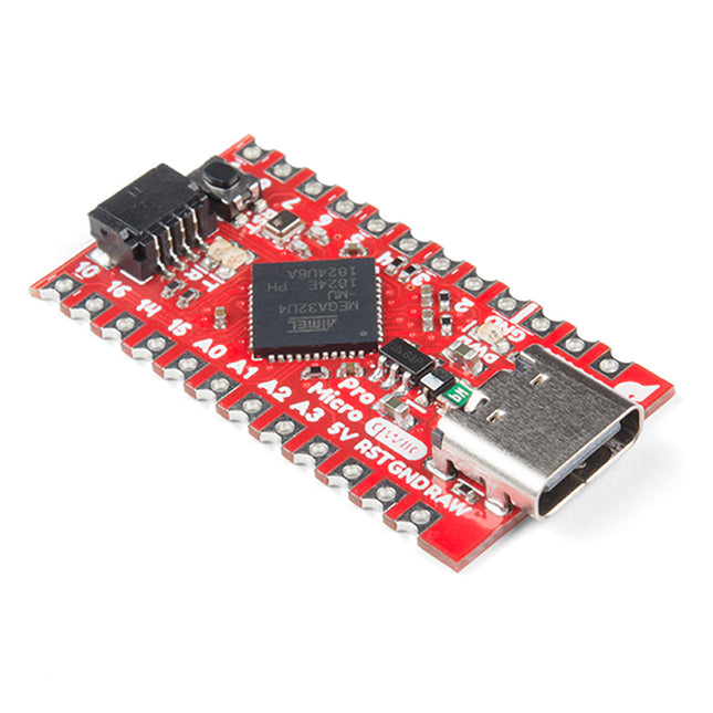
SparkFun SparkFun Qwiic Pro Micro - USB-C (ATmega32U4)
This tiny little board does all of the neat Arduino tricks that you're familiar with: nine channels of 10-bit ADC, five PWM pins, 12 DIOs as well as hardware serial connections Rx and Tx. Running at 5 V and 16 MHz, this board will remind you a lot of your other favourite Arduino-compatible boards, but this little guy can go just about anywhere. There is a voltage regulator on board so it can accept voltage up to 6 VDC. If you're supplying unregulated power to the board, be sure to connect to the 'RAW' pin on not VCC. The reset button's benefit is to quickly reset the board or place it into bootloader mode without the need to take out a piece of the jumper wire. The USB micro-b connector has been replaced with the USB type C connector. The through-hole pads have castellated edges for each pin to add a lower profile in your projects should you decide to build it into another assembly during production. Finally, a Qwiic connector is populated on the board's bottom to add Qwiic enabled I²C devices to your projects easily! Features ATmega32U4 running at 5 V / 16 MHz AP2112 3.3 V Voltage Regulator Supported under Arduino IDE v1.0.1+ On-Board USB-C connector for programming PTH Pads w/ Castellated Edges 9 x 10-bit ADC pins 12 x Digital I/Os (5 are PWM capable) Hardware Serial Connections UART (i.e. Rx and Tx) Qwiic Connector for I²C SPI Small Arduino-Compatible Board Reset Button Dimensions: 1.3in x 0.7in
€ 24,95
Members € 22,46
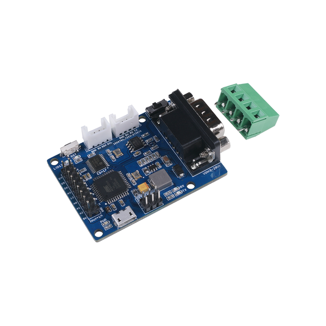
Seeed Studio Seeed Studio CANBed - Arduino CAN-BUS Development Kit (ATmega32U4 with MCP2515 and MCP2551)
Features ATmega32U4 with Arduino Leonardo bootloader on the board MCP2515 CAN Bus controller and MCP2551 CAN Bus transceiver OBD-II and CAN standard pinout selectable at the sub-D connector Compatible with Arduino IDE Parameter Value MCU ATmega32U4(with Arduino Leonardo bootloader) Clock Speed 16 MHz Flash Memory 32 KB SRAM 2.5 KB EEPROM 1 KB Operate Voltage(CAN-BUS) 9 V - 28 V Operate Voltage (MicroUSB) 5 V Input Interface sub-D Included CANBed PCBA sub-D connector 4PIN Terminal 2 x 4PIN 2.0 Connector 1 x 9x2 2.54 Header 1 x 3x2 2.54 Header
€ 32,95
Members € 29,66
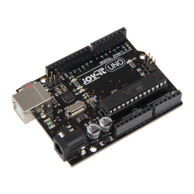
JOY-iT JOY-iT Uno R3 DIP
The Uno R3 board is the perfect microcontroller for those who want to enter the programming world without any fuss. Its ATMega328 microcontroller provides you with enough power for your ideas and projects. The Uno board has a USB type B connector so that you can easily use it with programs – of course via the well-known programming environment Arduino IDE. You can connect it to the power source via the USB port or alternatively use its own power connection. Please note: The CH341 driver must be installed beforehand so that Uno board is recognized by the Arduino IDE. Microcontroller ATmega 328 Clock speed 16 MHz Operating voltage 5 V Input voltage 5-10 V Digital I/O Pins 14 with PWM 6 USB 1x SPI 1x I²C 1x ICSP 1x Flash Memory 32 KB EEPROM 1x
€ 14,95
Members € 13,46
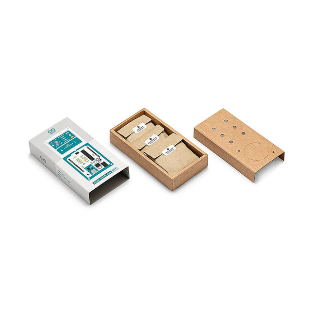
Arduino Arduino Make-Your-Uno Kit
Learn the basics of electronics by assembling manually your Arduino Uno, become familiar with soldering by mounting every single component, and then unleash your creativity with the only kit that becomes a synth! The Arduino Make-Your-Uno kit is really the best way to learn how to solder. And when you are done, the packaging allows you to build a synth and make your music. A kit with all the components to build your very own Arduino Uno and audio synthesizer shield. The Make-Your-Uno kit comes with a complete set of instructions in a dedicated content platform. This includes video material, a 3D interactive viewer for following detailed instructions, and how to program your board once it is finished. This kit contains: Arduino Make-Your-Uno 1x Make-Your-Uno PCB 1x USB C Serial adapter Board 7x Resistors 1k Ohm 2x Resistors 10k Ohm 2x Resistors 1M Ohm 1x Diode (1N4007) 1x 16 MHz Crystal 4x Yellow LEDs 1x Green LED 1x Push-Button 1x MOSFET 1x LDO (3.3 V) 1x LDO (5 V) 3x Ceramic capacitors (22pF) 3x Electrolytic capacitors (47uF) 7x Polyester capacitors (100nF) 1x Socket for ATMega 328p 2x I/O Connectors 1x Connector header 6 pins 1x Barrel jack connector 1x ATmega 328p Microcontroller Arduino Audio Synth 1x Audio Synth PCB 1x Resistor 100k Ohm 1x Resistor 10 Ohm 1x Audio amplifier (LM386) 1x Ceramic capacitors (47nF) 1x Electrolytic capacitors (47uF) 1x Electrolytic capacitors (220uF) 1x Polyester capacitor (100nF) 4x connectors pin header 6x potentiometer 10k Ohm with plastic knobs Spare parts 2x Electrolytic capacitors (47uF) 2x Polyester capacitor (100nF) 2x Ceramic capacitors (22pF) 1x Push-Button 1x Yellow LEDs 1x Green LED Mechanical parts 5x Spacers 12 mm 11x Spacers 6 mm 5x screw nuts 2x screws 12 mm
€ 79,95
Members € 71,96
Elektor Digital Explore ATtiny Microcontrollers using C and Assembly Language (E-book)
AVR Architecture and Programming An in-depth look at the 8-bit AVR architecture found in ATtiny and ATmega microcontrollers, mainly from a software and programming point of view. Explore the AVR architecture using C and assembly language in Microchip Studio (formerly Atmel Studio) with ATtiny microcontrollers. Learn the details of how AVR microcontrollers work internally, including the internal registers and memory map of ATtiny devices. Program ATtiny microcontrollers using an Atmel-ICE programmer/debugger, or use a cheap hobby programmer, or even an Arduino Uno as a programmer. Most code examples can be run using the Microchip Studio AVR simulator. Learn to write programs for ATtiny microcontrollers in assembly language. See how assembly language is converted to machine code instructions by the assembler program. Find out how programs written in the C programming language end up as assembly language and finally as machine code instructions. Use the Microchip Studio debugger in combination with a hardware USB programmer/debugger to test assembly and C language programs, or use the Microchip Studio AVR simulator. DIP packaged ATtiny microcontrollers are used in this volume for easy use on electronic breadboards, targeting mainly the ATtiny13(A) and ATtiny25/45/85. Learn about instruction timing and clocks in AVR microcontrollers using ATtiny devices. Be on your way to becoming an AVR expert with advanced debugging and programming skills.
€ 29,95
Members € 23,96
Explore ATtiny Microcontrollers using C and Assembly Language
AVR Architecture and Programming An in-depth look at the 8-bit AVR architecture found in ATtiny and ATmega microcontrollers, mainly from a software and programming point of view. Explore the AVR architecture using C and assembly language in Microchip Studio (formerly Atmel Studio) with ATtiny microcontrollers. Learn the details of how AVR microcontrollers work internally, including the internal registers and memory map of ATtiny devices. Program ATtiny microcontrollers using an Atmel-ICE programmer/debugger, or use a cheap hobby programmer, or even an Arduino Uno as a programmer. Most code examples can be run using the Microchip Studio AVR simulator. Learn to write programs for ATtiny microcontrollers in assembly language. See how assembly language is converted to machine code instructions by the assembler program. Find out how programs written in the C programming language end up as assembly language and finally as machine code instructions. Use the Microchip Studio debugger in combination with a hardware USB programmer/debugger to test assembly and C language programs, or use the Microchip Studio AVR simulator. DIP packaged ATtiny microcontrollers are used in this volume for easy use on electronic breadboards, targeting mainly the ATtiny13(A) and ATtiny25/45/85. Learn about instruction timing and clocks in AVR microcontrollers using ATtiny devices. Be on your way to becoming an AVR expert with advanced debugging and programming skills.
€ 37,95
Members € 34,16
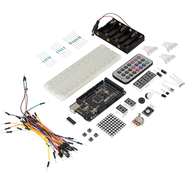
JOY-iT JOY-iT Mega 2560 Microcontroller Learning Kit
The set consists of 86 pieces. These are a Mega 2560 microcontroller board, 2 breadboards, one USB cable, a battery holder, an IR remote control, one 4-digit segment display, 2x 1-digit segment displays, one 8x8 LED matrix, a potentiometer, one RGB LED, 5 blue LEDs, 5 yellow LEDs, 5 red LEDs, 4 buttons,a temperature sensor (LM35), 2 tilt switches, an IR receiver, one active buzzer, one passive buzzer, 3 photo resistors, a flame sensor, 18 resistors (5x 1 kΩ, 8x 220 Ω, 5x 10 kΩ), a shift register (SN74HC595N) and 30 cables. Features Model Mega 2560 Learning Kit Microcontroller ATmega 2560 R3 Projects 20 different projects Manual Incl. project manual of 63 pages as download and a printed quick reference guide Specifications Input Voltage 7-12 V Ipput Voltage (max.) 6-20 V Digital IO 54 (14 with PWM) Analog IO 16 DC Current IO 40 mA DC Current 3.3 V 50 mA Memory 256 kB (8 kB Bootloader) SRAM 8 kB EEPROM 4 kB Clock Speed 16 MHz Dimensions 11.52 x 53,3 mm
€ 54,95
Members € 49,46
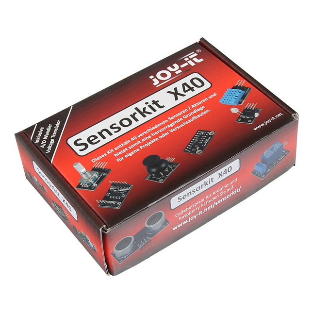
JOY-iT JOY-iT Sensor Kit X40
This high-quality sensor kit has been specially developed for the most common open-source platforms. It is compatible with single-board computers (Raspberry Pi, Banana Pi, CubieBoard, CubieTruck, Beaglebone, pcDuino) and microcontrollers (Arduino, ATmega, AVR, PIC, STM32, etc.). It contains a total of 40 different sensors. You can either solder the sensors or stick them on a board to work on different circuits or experiments. Comprehensive sensor set with 40 sensors including analogue- and voltage-converter High-quality, reliable sensors Universally applicable Kit contents KY-001 Temperature sensor module KY-002 Vibration switch module KY-003 Hall magnetic field sensor module KY-004 Button module KY-005 Infrared transmitter module KY-006 Passive Piezo buzzer module KY-009 RGB LED SMD module KY-010 Light barrier module KY-011 2-color (Red+Green) 5 mm LED module KY-012 Active Piezo buzzer module KY-013 Temperature sensor module KY-015 combi sensor temperature+humidity KY-016 RGB 5 mm LED module KY-017 Tilt switch module KY-018 Photoresistor module KY-019 5 V relais module KY-020 Tilt switch module KY-021 Mini magnetic reed module KY-022 Infrared receiver module KY-023 Joystick module (XY-axis) KY-024 Linear magnetic hall sensor KY-025 Reed module KY-026 Flame sensor module KY-027 Magic light cup module KY-028 Temperature sensor module (Thermistor) KY-029 2-color (Red+Green) 3 mm LED module KY-031 Knock sensor module KY-032 Obstacle detect module KY-033 Tracking sensor module KY-034 7 clour LED flash module KY-035 Bihor magnetic sensor module KY-036 Metal-touch sensor module KY-037 Microphone sensor module (high sensitivity) KY-038 Microphone sound sensor module KY-039 Heartbeat sensor module KY-040 Rotary Encoder KY-050 Ultrasonic distance sensor KY-051 Voltage Translator / Level Shifter KY-052 Pressure sensor / Temperatur sensor (BMP180) KY-053 Analog-digital converter A detailed list with a short description of the functions, programming examples and software, can be found at http://sensorkit.en.joy-it.net.
€ 59,95
Members € 53,96
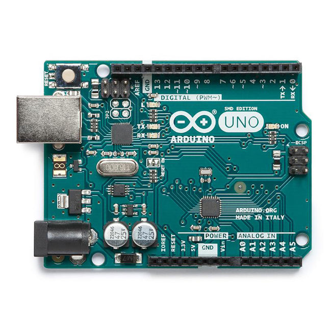
Arduino Arduino Uno Rev3 SMD
The Uno differs from all preceding boards in that it does not use the FTDI USB-to-serial driver chip. Additional features coming with the R3 version are: ATmega16U2 instead of 8U2 as a USB-to-Serial converter. 1.0 pinout: added SDA and SCL pins for TWI communication placed near to the AREF pin and two other new pins placed near to the RESET pin, the IOREF that allow the shields to adapt to the voltage provided from the board and the second one is a not connected pin, that is reserved for future purposes. stronger RESET circuit. Microcontroller ATmega328P Operating Voltage 5 V Input Voltage 7 V - 12 V Digital I/O Pins 14 PWM Pins 6 Analog Input Pins 8 DC Current per I/O Pin 20 mA DC Current for 3.3 V Pin 50 mA Flash Memory 32 KB (ATmega328P) of which 0.5 KB used by bootloader SRAM 2 KB EEPROM 1 KB Clock Speed 16 MHz LED_Builtin 13 Length 68.6 mm Width 53.4 mm Weight 25 g
€ 22,95
Members identical
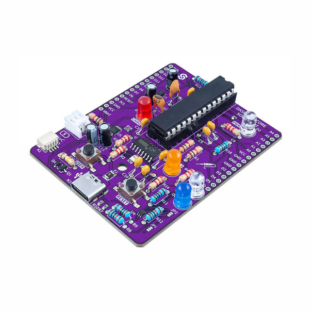
Make your own Dasduino Solder Kit
If you’re looking for a simple way to start soldering or just want to make your own Dasduino, this soldering set is a great opportunity. "Make your own Dasduino CORE" is an educational set for learning the skill of soldering, with which you end up with a functional microcontroller board. As with the other SMD versions of the Dasduino CORE boards we offer, the possibilities are endless. It is based on the ATmega328P microcontroller, and all SMD components are already soldered on the board. The set also includes a THT socket for the microcontroller, which simplifies the replacement of the microcontroller should it ever become necessary. Included 1x PCB 7x Capacitors (100nF) 4x Capacitors (2.2uF) 2x Capacitors (22pF) 5x Resistors (2.2 kOhm) 5x Resistors (10 kOhm) 3x Resistors (1 kOhm) 1x Resistor (100 kOhm) 1x Resistor (100 ohm) 1x JST battery connector 1x LED (purple) 1x LED (white) 1x LED (blue) 1x LED (red) 1x LED (orange) 1x Socket for ATmega328P 1x ATmega328P microcontroller
€ 24,95
Members € 22,46
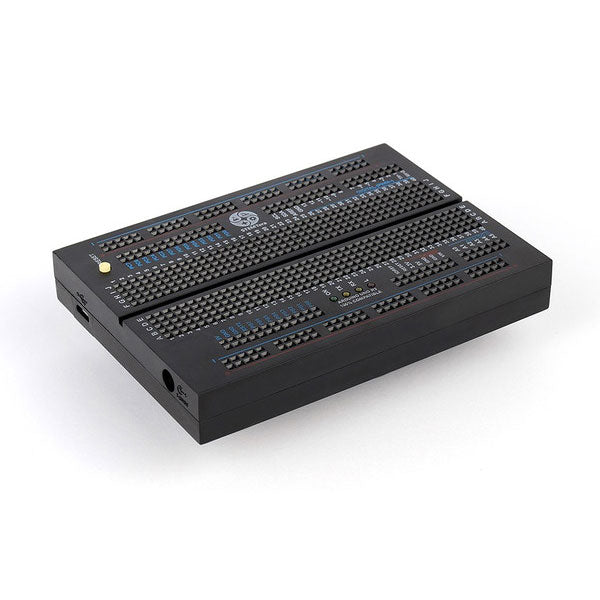
STEMTera STEMTera - Arduino Uno compatible Breadboard
STEMTera is a programmable breadboard module, compatible with Arduino Uno. It has two microcontrollers built in: ATmega328P and ATmega32U2 and the I/O (40 mA per pin) are accessible without cabling. The underside of the board (112 x 80 x 17 mm) is compatible with LEGO. Specifications Pin-to-pin compatible with Arduino Uno Mechanically compatible with LEGO blocks Two microcontrollers (41 I/O of which 9 as PWM) USB interface with ATmega32U2 using LUFA (Lightweight USB Framework for AVRs) for keyboard, joystick, MIDI, etc... Programming with the Arduino IDE (micro-USB) Reset button, 4 LEDs (including TX, RX, Power), power connector Power via micro-USB or 7...20 VDC on socket 5,5 x 2,1 mm (+ center) Multiple programming environments: Atmel Studio Arduino IDE AVR-GCC AVR-GCC with LUFA library Scratch etc Remarks: Body colour is black | Cables are not included | Shields with ICSP under the PCB can not be inserted Microcontrollers ATmega328P: 14 pins of I/O including 6 PWM 6 analog inputs (10 bit ADC) I²C, SPI and serial Interrupt controller ATmega32U2: 21 pins of I/O Flash Memory: 32 KB SRAM: 2 KB EEPROM: 1 KB Clock: 16 MHz Downloads Beginner's Guide
€ 69,95
Members € 62,96
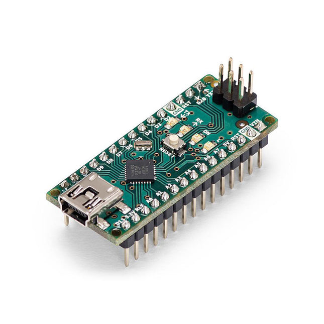
Arduino Arduino Nano
The Arduino Nano is a small, complete, and breadboard-friendly board based on the ATmega328 (Arduino Nano 3.x). It has more or less the same functionality of the Arduino Duemilanove but in a different package. It lacks only a DC power jack and works with a Mini-B USB cable instead of a standard one. The Nano was designed and is being produced by Gravitech. Specifications Microcontroller ATmega328 Operating Voltage (logic level) 5 V Input Voltage (recommended) 7-12 V Input Voltage (limits) 6-20 V Digital I/O Pins 14 (of which 6 provide PWM output) Analog Input Pins 8 DC Current per I/O Pin 40 mA Flash Memory 16 KB (ATmega168) or 32 KB (ATmega328) of which 2 KB used by bootloader SRAM 1 KB (ATmega168) or 2 KB (ATmega328) EEPROM 512 bytes (ATmega168) or 1 KB (ATmega328) Clock Speed 16 MHz Dimensions 0.73 x 1.70' (18 x 45 mm) Power The Arduino Nano can be powered via the Mini-B USB connection, 6-20 V unregulated external power supply (pin 30), or 5 V regulated external power supply (pin 27). The power source is automatically selected to the highest voltage source. Memory The ATmega168 has 16 KB of flash memory for storing code (of which 2 KB is used for the bootloader), 1 KB of SRAM and 512 bytes of EEPROM The ATmega328 has 32 KB of flash memory for storing code, (also with 2 KB used for the bootloader), 2 KB of SRAM and 1 KB of EEPROM. Input and Output Each of the 14 digital pins on the Nano can be used as an input or output, using pinMode(), digitalWrite(), and digitalRead() functions. They operate at 5 V. Each pin can provide or receive a maximum of 40 mA and has an internal pull-up resistor (disconnected by default) of 20-50 kOhms. Communication The Arduino Nano has a number of facilities for communicating with a computer, another Arduino, or other microcontrollers. The ATmega168 and ATmega328 provide UART TTL (5V) serial communication, which is available on digital pins 0 (RX) and 1 (TX). An FTDI FT232RL on the board channels this serial communication over USB and the FTDI drivers (included with the Arduino software) provide a virtual com port to software on the computer. The Arduino software includes a serial monitor which allows simple textual data to be sent to and from the Arduino board. The RX and TX LEDs on the board will flash when data is being transmitted via the FTDI chip and USB connection to the computer (but not for serial communication on pins 0 and 1). A SoftwareSerial library allows for serial communication on any of the Nano's digital pins. Programming The Arduino Nano can be programmed with the Arduino software (download). The ATmega168 or ATmega328 on the Arduino Nano comes with a bootloader that allows you to upload new code to it without the use of an external hardware programmer. It communicates using the original STK500 protocol (reference, C header files). You can also bypass the bootloader and program the microcontroller through the ICSP (In-Circuit Serial Programming) header using Arduino ISP or similar; see these instructions for details. Automatic (Software) Reset Rather than requiring a physical press of the reset button before an upload, the Arduino Nano is designed in a way that allows it to be reset by software running on a connected computer. One of the hardware flow control lines (DTR) of theFT232RL is connected to the reset line of the ATmega168 or ATmega328 via a 100 nF capacitor. When this line is asserted (taken low), the reset line drops long enough to reset the chip. The Arduino software uses this capability to allow you to upload code by simply pressing the upload button in the Arduino environment. This means that the bootloader can have a shorter timeout, as the lowering of DTR can be well-coordinated with the start of the upload.
€ 22,95
Members € 20,66


