Trade products
-
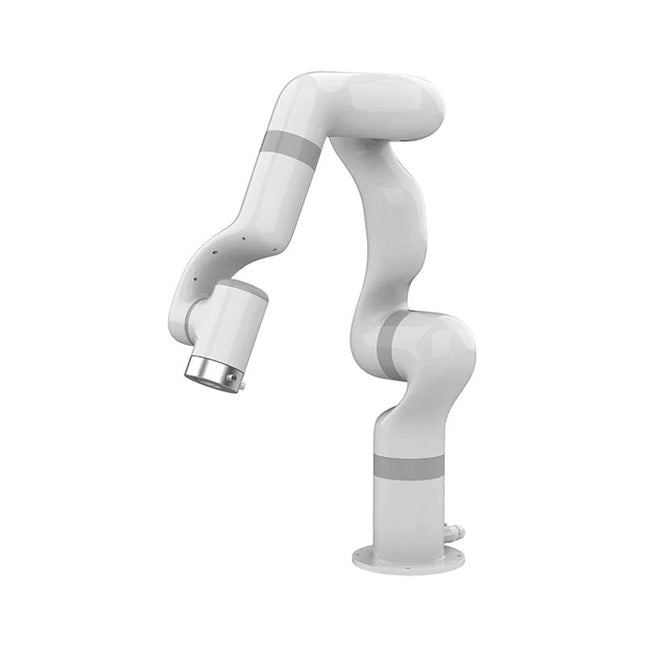
UFactory UFactory 850 Robotic Arm
UFactory 850 is the most powerful robot with industrial grade performance. Features 6DoF Payload: 5 kg Reach: 850 mm Repeatability: 0.02 mm Weight: 20 kg Applications Glambot Welding Screwdriving Robot Vision Industrial Production Designed for both mobile platforms and your workbench The AC control box contains an AC-DC adapter inside, 100-240 V AC is all ready to go. The DC control box supports 48-72 V wide inputs, it perfectly fits the battery system on your mobile platform. Flexible Deployment With Safe Feature Hand teaching, space-saving and easy to re-deploy to multiple applications without changing your production layout. Perfectly for recurrent tasks. Collision detection is available for all of our cobots. Your safety is always the top priority. Graphical Interface For Beginner-Friendly Programming Compatible with various operation systems, including macOS and Windows. Web-based technology compatible with all major browsers. Drag and drop to create your code in minutes. Powerful And Open Source SDK At Your Fingertips Fully functional open-source Python/C++ SDK provides more flexible programming. ROS/ROS2 packages are ready-to-go. Example codes help you to deploy the robotic arm smoothly. Specifications UFactory 850 xArm 5 xArm 6 xArm 7 Payload 5 kg 3 kg 5 kg 3.5 kg Reach 850 mm 700 mm 700 mm 700 mm Degrees of freedom 6 5 6 7 Repeatability ±0.02 mm ±0.1 mm ±0.1 mm ±0.1 mm Maximum Speed 1 m/s 1 m/s 1 m/s 1 m/s Weight (robot arm only) 20 kg 11.2 kg 12.2 kg 13.7 kg Maximum Speed 180°/s 180°/s 180°/s 180°/s Joint 1 ±360° ±360° ±360° ±360° Joint 2 -132°~132° -118°~120° -118°~120° -118°~120° Joint 3 -242°~3.5° -225°~11° -225°~11° ±360° Joint 4 ±360° -97°~180° ±360° -11°~225° Joint 5 -124°~124° ±360° -97°~180° ±360° Joint 6 ±360° ±360° -97°~180° Joint 7 ±360° Hardware Ambient Temperature Range 0-50°C Power Consumption Typical 240 W, max 1000 W Input Power Supply 48 V DC, 20.8 A Footprint Ø 190 mm Materials Aluminum, Carbon Fiber Base Connector Type M8x4 ISO Class Cleanroom 5 Robot Mounting Any End Effector Communication Protocol Modbus RTU End Effector I/O 2x DI / 2x DO / 2x AI / 1x RS485 Communication Mode Ethernet Included 1x UFactory 850 robotic arm 1x AC control box 1x Control box power cable
€ 11.779,00
Best Price
-
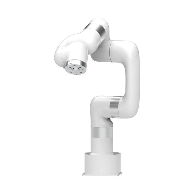
UFactory UFactory xArm 7
This multi-axis robot perfectly balances power and size. Features 6 Axis Payload: 3.5 kg Reach: 700 mm Repeatability: 0.1 mm Max Speed 1000 mm/s Applications Machine Tending Bin Picking Mobile platform Lab Automation Robotic Research Durable Collaborative robots for your automation Industrial-grade harmonic drive and servomotors guarantee 24/7 working without stop. Crafted from Carbon fiber, 15 kg weight makes it possible for easier deployment. Flexible deployment with safe feature Hand teaching, lightweight, space-saving and easy to re-deploy to multiple applications without changing your production layout. Perfectly for recurrent tasks. Collision detection is available for all of our cobots. Your safety is always the top priority. Graphical interface for beginner-friendly programming Compatible with various of operation systems, including macOS and Windows. Web-based technology compatible with all major browsers. Drag and drop to create your code in minutes. Powerful and open source SDK at your fingertips Fully functional open-source Python/C++ SDK provides more flexible programming. ROS/ROS2 packages are ready-to-go. Example codes help you to deploy the robotic arm smoothly. Specifications UFactory 850 xArm 5 xArm 6 xArm 7 Payload 5 kg 3 kg 5 kg 3.5 kg Reach 850 mm 700 mm 700 mm 700 mm Degrees of freedom 6 5 6 7 Repeatability ±0.02 mm ±0.1 mm ±0.1 mm ±0.1 mm Maximum Speed 1 m/s 1 m/s 1 m/s 1 m/s Weight (robot arm only) 20 kg 11.2 kg 12.2 kg 13.7 kg Maximum Speed 180°/s 180°/s 180°/s 180°/s Joint 1 ±360° ±360° ±360° ±360° Joint 2 -132°~132° -118°~120° -118°~120° -118°~120° Joint 3 -242°~3.5° -225°~11° -225°~11° ±360° Joint 4 ±360° -97°~180° ±360° -11°~225° Joint 5 -124°~124° ±360° -97°~180° ±360° Joint 6 ±360° ±360° -97°~180° Joint 7 ±360° Hardware Ambient Temperature Range 0-50°C Power Consumption Min 8.4 W, Typical 200 W, max 400 W Input Power Supply 24 V DC, 16.5 A Footprint Ø 126 mm Materials Aluminum, Carbon Fiber Base Connector Type M5x5 ISO Class Cleanroom 5 Robot Mounting Any End Effector Communication Protocol Modbus RTU(rs485) End Effector I/O 2x DI/2x DO/2x AI/1x RS485 Communication Mode Ethernet Included 1x xArm 7 robotic arm 1x AC control box 1x Robotic arm power cable 1x Robotic arm end effector adapter cable 1x Robotic arm signal cable 1x Control box power cable 1x Network cable 1x Mounting tool 1x Quick start guide
€ 14.569,00
Best Price
-

UFactory UFactory xArm 6
This multi-axis robot perfectly balances power and size. Features Payload: 5 kg Reach: 700 mm Repeatability: 0.1 mm Max Speed 1000 mm/s Applications Machine Tending Bin Picking Mobile platform Lab Automation Robotic Research Durable Collaborative robots for your automation Industrial-grade harmonic drive and servomotors guarantee 24/7 working without stop. Crafted from Carbon fiber, 15 kg weight makes it possible for easier deployment. Flexible deployment with safe feature Hand teaching, lightweight, space-saving and easy to re-deploy to multiple applications without changing your production layout. Perfectly for recurrent tasks. Collision detection is available for all of our cobots. Your safety is always the top priority. Graphical interface for beginner-friendly programming Compatible with various of operation systems, including macOS and Windows. Web-based technology compatible with all major browsers. Drag and drop to create your code in minutes. Powerful and open source SDK at your fingertips Fully functional open-source Python/C++ SDK provides more flexible programming. ROS/ROS2 packages are ready-to-go. Example codes help you to deploy the robotic arm smoothly. Specifications UFactory 850 xArm 5 xArm 6 xArm 7 Payload 5 kg 3 kg 5 kg 3.5 kg Reach 850 mm 700 mm 700 mm 700 mm Degrees of freedom 6 5 6 7 Repeatability ±0.02 mm ±0.1 mm ±0.1 mm ±0.1 mm Maximum Speed 1 m/s 1 m/s 1 m/s 1 m/s Weight (robot arm only) 20 kg 11.2 kg 12.2 kg 13.7 kg Maximum Speed 180°/s 180°/s 180°/s 180°/s Joint 1 ±360° ±360° ±360° ±360° Joint 2 -132°~132° -118°~120° -118°~120° -118°~120° Joint 3 -242°~3.5° -225°~11° -225°~11° ±360° Joint 4 ±360° -97°~180° ±360° -11°~225° Joint 5 -124°~124° ±360° -97°~180° ±360° Joint 6 ±360° ±360° -97°~180° Joint 7 ±360° Hardware xArm Robot specs Ambient Temperature Range 0-50°C Power Consumption Min 8.4 W, Typical 200 W, max 400 W Input Power Supply 24 V DC, 16.5 A Footprint Ø 126 mm Materials Aluminum, Carbon Fiber Base Connector Type M5x5 ISO Class Cleanroom 5 Robot Mounting Any End Effector Communication Protocol Modbus RTU(rs485) End Effector I/O 2x DI/2x DO/2x AI/1x RS485 Communication Mode Ethernet Included 1x xArm 6 robotic arm 1x AC control box 1x Robotic arm power cable 1x Robotic arm end effector adapter cable 1x Robotic arm signal cable 1x Control box power cable 1x Network cable 1x Mounting tool 1x Quick start guide
€ 11.259,00
Best Price
-

UFactory UFactory xArm 5 Lite
A multi-axis robot perfectly balances power and size Features 5 Axis Payload: 3 kg Reach: 700 mm Repeatability: 0.1 mm Max Speed 1000 mm/s Applications Machine Tending Bin Picking Mobile platform Lab Automation Robotic Research Durable Collaborative robots for your automation Industrial-grade harmonic drive and servomotors guarantee 24/7 working without stop. Crafted from Carbon fiber, 15 kg weight makes it possible for easier deployment. Flexible deployment with safe feature Hand teaching, lightweight, space-saving and easy to re-deploy to multiple applications without changing your production layout. Perfectly for recurrent tasks. Collision detection is available for all of our cobots. Your safety is always the top priority. Graphical interface for beginner-friendly programming Compatible with various of operation systems, including macOS and Windows. Web-based technology compatible with all major browsers. Drag and drop to create your code in minutes. Powerful and open source SDK at your fingertips Fully functional open-source Python/C++ SDK provides more flexible programming. ROS/ROS2 packages are ready-to-go. Example codes help you to deploy the robotic arm smoothly. Specifications UFactory 850 xArm 5 xArm 6 xArm 7 Payload 5 kg 3 kg 5 kg 3.5 kg Reach 850 mm 700 mm 700 mm 700 mm Degrees of freedom 6 5 6 7 Repeatability ±0.02 mm ±0.1 mm ±0.1 mm ±0.1 mm Maximum Speed 1 m/s 1 m/s 1 m/s 1 m/s Weight (robot arm only) 20 kg 11.2 kg 12.2 kg 13.7 kg Maximum Speed 180°/s 180°/s 180°/s 180°/s Joint 1 ±360° ±360° ±360° ±360° Joint 2 -132°~132° -118°~120° -118°~120° -118°~120° Joint 3 -242°~3.5° -225°~11° -225°~11° ±360° Joint 4 ±360° -97°~180° ±360° -11°~225° Joint 5 -124°~124° ±360° -97°~180° ±360° Joint 6 ±360° ±360° -97°~180° Joint 7 ±360° Hardware Ambient Temperature Range 0-50°C Power Consumption Min 8.4 W, Typical 200 W, max 400 W Input Power Supply 24 V DC, 16.5 A Footprint Ø 126 mm Materials Aluminum, Carbon Fiber Base Connector Type M5x5 ISO Class Cleanroom 5 Robot Mounting Any End Effector Communication Protocol Modbus RTU(rs485) End Effector I/O 2x DI/2x DO/2x AI/1x RS485 Communication Mode Ethernet Included 1x xArm 5 robotic arm 1x AC control box 1x Robotic arm power cable 1x Robotic arm end effector adapter cable 1x Robotic arm signal cable 1x Control box power cable 1x Network cable 1x Mounting tool 1x Quick start guide
€ 7.285,00
Best Price
-
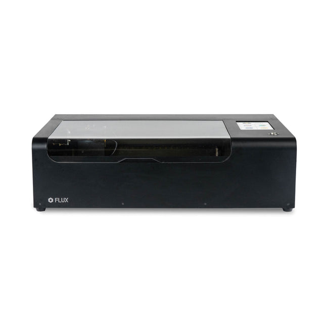
FLUX FLUX Beamo Laser Cutter
FLUX Beamo is a powerful and compact 30 W CO2 desktop laser cutter that can cut and engrave a range of materials including metals. With its easy-to-use design, intuitive controls and features, you can effortlessly create amazing things. Built-in HD camera Cutting and engraving is hassle-free with our preview mode. Place your material, preview the work area in the Beam Studio software and engrave. Your design comes out exactly as shown in the preview. Integrated safety features If left opened, auto pause ensures the laser stops. The internal water cooling system provides a stable cutting process. Plus, you can stop production with a single switch at any time. Powerful high resolution laser The Beamo ultra thin laser can engrave exceptional detail down to 0.05 mm wide with a clear resolution of 1,000 dpi. Fitting for any craft or small business project. The most precise compact CO2 laser engraver Beamo's sleek, modern and compact design fits beautifully in any home, school or workshop space. It comes pre-assembled with a metal body and acrylic lid, measuring 615 x 445 x 177 mm. Bring your designs to life with its 30 W CO2 laser operating on a 30 x 21 cm work area. Safe for home and school Beamo prioritises safety with its thoughtful design features. The machine is fully enclosed, and it automatically pauses if the lid is opened during a task. Additionally, there is a single switch for immediate machine shutdown in case of emergencies. Beamo is equipped with a Class 1 laser, which is completely safe under normal use. Specifications Dimensions 615 x 445 x 177 mm Weight 22 kg Work Area 300 x 210 x 45 mm (11.81 x 8,27 x 1.77') Camera Preview Area 300 x 195 mm Voltage AC 110 V / 220 V Touch Panel 1024 x 600 LCD Camera HD CMOS I/O Wi-Fi / Ethernet Laser Spec 30 W CO₂ Laser Laser Moving Speed 0~300 mm/s Laser Cutting Thickness 0-5 mm (varies by material) Software Mode Vector / Graphic (monochrome, gray scale) Operating System Windows / macOS / Linux Software File Type JPG / PNG / SVG / DXF Included FLUX Beamo (distilled water included) Vent hose Duct Clamp Double sided tape to align the mirror's Ethernet cable Vent Hose Double head wrench Wood piece Torx screwdriver and 2.5 mm hexagonal wrench Funnel 1x Laser Cutter Lubricant Power cord Wifi Dongle USB Beamo Manual Honey Comb Platform (30 W) Downloads Firmware
€ 2.660,00
Best Price
-
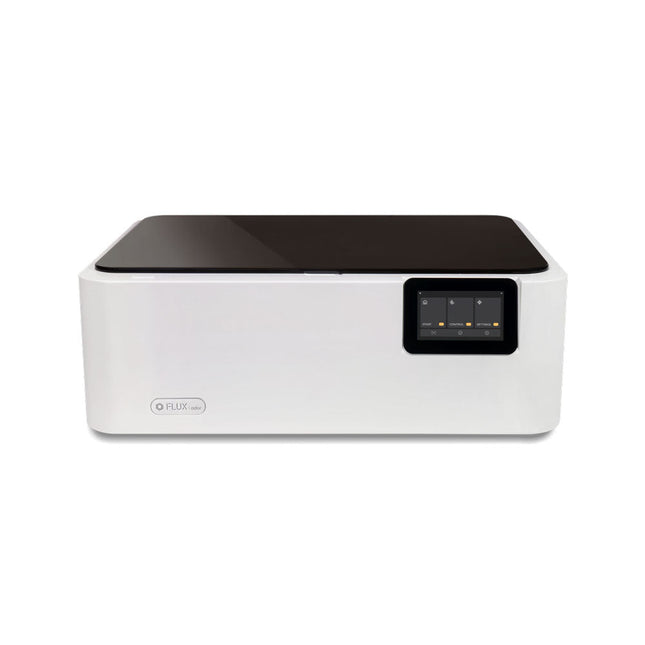
FLUX FLUX Ador Laser Cutter (20 W)
FLUX Ador is the world's first color printing laser cutter. Powered by three high-quality, interchangeable modules, Ador enables you to engrave and cut though a wide range of materials while enhancing your projects with a pop of color. New creative potential with Ador Whether you’re an educator, small business, crafter or designer, with Ador, the application boundary is for you to define. Easy to use Place material then autofocus Drag and drop your design Engrave, cut or print Project Completed! Big workspace, big ideas Ador offers a big working space of 430 x 300 mm, with a depth of 30 mm, expanding the horizons of your creativity. Specifications Dimensions 637 x 488 x 226 mm Weight 19 kg Work Area X&Y: 20 W Diode laser: 430 x 300 mm (X & Y varies with different modules)Z: 30 mm (for all modules) & 20 mm (with prism) Camera Preview Area Whole work area Voltage AC 110-240 V Touch Panel Yes, 8 inches (diagonal) Camera 8 MP I/O USB / WiFi Laser Spec W Diode laser Module Laser Moving Speed 0~400 mm/s Laser Cutting Thickness Varies for different materials Software Mode Vector / Graphic (monochrome, gray scale) Operating System Windows / macOS / Linux Software File Type JPG / PNG / SVG / DXF Included FLUX Ador 20 W diode laser module 6x prism lift Power adapter Power cord Hex key Vent Hose Vent hose Duct Clamp Wooden test piece Laser Cutter Lubricant Downloads Firmware
€ 1.935,00
Best Price
-

Rigol Rigol DSA815-TG Spectrum Analyzer (9 kHz – 1.5 GHz)
Highlights Frequency: 1.5 GHz DANL: -155 dBm Phase Noise: -80 dBc/Hz RBW: 10 Hz Tracking Generator Specifications All-Digital IF Technology Frequency Range from 9 kHz up to 1.5 GHz Min. -161 dBm Displayed Average Noise Level (Typ.) Min. < -98 dBc/Hz @ 10 kHz Offset Phase Noise Level Measurement Uncertainty < 0.8 dB 10 Hz Minimum Resolution Bandwidth Up to 1.5 GHz Tracking Generator Advanced Measurement Functions (Opt.) EMI Filter & Quasi-Peak Detector Kit (Opt.) VSWR Measurement Kit (Opt.) PC Software (Opt.) Optional RF TX/RX Training Kit Optional RF Accessories (Cable, Adaptor, Attenuator, Bridge ...) Complete Connectivity: LAN (LXI), USB Host & Device, GPIB (Opt.) 8 Inch WVGA (800x480) Display Compact Size, Light Weight Design Included 1x Rigol DSA815-TG Spectrum Analyzer 1x Power cord 1x USB cable
€ 974,66
-

Rigol Rigol RSA3015E-TG Real-time Spectrum Analyzer (9 kHz – 1.5 GHz)
Highlights Frequency: 1.5 GHz DANL: -161 dBm Phase Noise: -102 dBc/Hz RBW: 1 Hz Specifications Ultra-Real technology Frequency: up to 1.5 GHz Displayed average noise level (DANL): <-161 dBm (typical) Phase noise: <-102 dBc/Hz (typical) Level measurement uncertainty: <1.0 dB 1.5 GHz tracking generator Min. RBW 1 Hz Up to 10 MHz real-time analysis bandwidth Multiple measurement modes Various advanced measurement functions EMI measurement application (option) Multiple trigger modes and trigger masks Density, spectrogram, and other display modes PC software options 10.1'' capacitive multi-touch screen; supporting touch gestures USB, LAN, HDMI and other communication and display interfaces Included 1x Rigol RSA3015E-TG Spectrum Analyzer 1x Power cord 1x USB cable
€ 2.176,79
-

Rigol Rigol DG2102 Function/Arbitrary Waveform Generator (100 MHz)
Highlights Output Frequency (Sine): 100 MHz Output Frequency (Square): 25 MHz Channels: 2 Arbitrary Waveform Length: 16 Mpts Features Unique SiFi II (Signal Fidelity II) technology: generate the arbitrary waveforms point by point; recover the signal without distortion; sample rate accurate and adjustable; jitter of all the output waveforms (including Sine, Pulse, etc.) as low as 200 ps 16 Mpts memory depth per channel for arbitrary waveforms Standard dual-channel with the same performance, equivalent to two independent signal sources High frequency stability: ±1 ppm; low phase noise: -105 dBc/Hz Built-in high-order harmonic generator (at most 8-order harmonics) Built-in 7 digits/s, 240 MHz bandwidth full featured frequency counter Up to 160 built-in arbitrary waveforms, covering the common signals in engineering application, medical electronics, auto electronics, math processing, and other various fields Sample rate up to 250 MSa/s, vertical resolution 16 bits Arbitrary waveform sequence editing function available; arbitrary waveforms also can be generated through the PC software Various analog and digital modulation functions: AM, FM, PM, ASK, FSK, PSK, and PWM. Standard waveform combine function, capable of outputting specified waveforms combined with the basic waveforms Standard channel tracking function, when enabled, all the parameters of both channels are updated based on users' configurations Standard interface: USB Host&Device and LAN (LXI Core 2011 Device); USB-GPIB function supported 4.3'' TFT Included 1x Rigol DG2102 Function/Arbitrary Waveform Generator 1x Power cord 1x USB cable
€ 1.087,79
-

Rigol Rigol DG2072 Function/Arbitrary Waveform Generator (70 MHz)
Highlights Output Frequency (Sine): 70 MHz Output Frequency (Square): 20 MHz Channels: 2 Arbitrary Waveform Length: 16 Mpts Features Unique SiFi II (Signal Fidelity II) technology: generate the arbitrary waveforms point by point; recover the signal without distortion; sample rate accurate and adjustable; jitter of all the output waveforms (including Sine, Pulse, etc.) as low as 200 ps 16 Mpts memory depth per channel for arbitrary waveforms Standard dual-channel with the same performance, equivalent to two independent signal sources High frequency stability: ±1 ppm; low phase noise: -105 dBc/Hz Built-in high-order harmonic generator (at most 8-order harmonics) Built-in 7 digits/s, 240 MHz bandwidth full featured frequency counter Up to 160 built-in arbitrary waveforms, covering the common signals in engineering application, medical electronics, auto electronics, math processing, and other various fields Sample rate up to 250 MSa/s, vertical resolution 16 bits Arbitrary waveform sequence editing function available; arbitrary waveforms also can be generated through the PC software Various analog and digital modulation functions: AM, FM, PM, ASK, FSK, PSK, and PWM. Standard waveform combine function, capable of outputting specified waveforms combined with the basic waveforms Standard channel tracking function, when enabled, all the parameters of both channels are updated based on users' configurations Standard interface: USB Host&Device and LAN (LXI Core 2011 Device); USB-GPIB function supported 4.3'' TFT Included 1x Rigol DG2072 Function/Arbitrary Waveform Generator 1x Power cord 1x USB cable
€ 882,09
-

Rigol Rigol DG2052 Function/Arbitrary Waveform Generator (50 MHz)
Highlights Output Frequency (Sine): 50 MHz Output Frequency (Square): 15 MHz Channels: 2 Arbitrary Waveform Length: 16 Mpts Features Unique SiFi II (Signal Fidelity II) technology: generate the arbitrary waveforms point by point; recover the signal without distortion; sample rate accurate and adjustable; jitter of all the output waveforms (including Sine, Pulse, etc.) as low as 200 ps 16 Mpts memory depth per channel for arbitrary waveforms Standard dual-channel with the same performance, equivalent to two independent signal sources High frequency stability: ±1 ppm; low phase noise: -105 dBc/Hz Built-in high-order harmonic generator (at most 8-order harmonics) Built-in 7 digits/s, 240 MHz bandwidth full featured frequency counter Up to 160 built-in arbitrary waveforms, covering the common signals in engineering application, medical electronics, auto electronics, math processing, and other various fields Sample rate up to 250 MSa/s, vertical resolution 16 bits Arbitrary waveform sequence editing function available; arbitrary waveforms also can be generated through the PC software Various analog and digital modulation functions: AM, FM, PM, ASK, FSK, PSK, and PWM. Standard waveform combine function, capable of outputting specified waveforms combined with the basic waveforms Standard channel tracking function, when enabled, all the parameters of both channels are updated based on users' configurations Standard interface: USB Host&Device and LAN (LXI Core 2011 Device); USB-GPIB function supported 4.3'' TFT Included 1x Rigol DG2052 Function/Arbitrary Waveform Generator 1x Power cord 1x USB cable
€ 652,19
-

Rigol Rigol DS1202Z-E 2-ch Oscilloscope (200 MHz)
Specifications Bandwidth: 200 MHz Analog Channels: 2 Real-time sample rate up to 1 GS/s Memory depth up to 24 Mpts Up to 30,000 wfms/s waveform capture rate Up to 60,000 frames hardware real-time waveform recording and playback functions Innovative 'UltraVision' technology Various trigger and bus decoding functions Low noise floor, vertical scale range: 1 mV/div to 10 V/div Various interfaces: USB Host&Device, LAN (LXI), AUX Compact size, light weight, easy to use 7 inch WVGA (800x480) TFT LCD, intensity graded color display Included 1x Rigol DS1202Z-E Oscilloscope 1x Power cord 1x USB cable 2x PVP2350 passive oscilloscope probe (350 MHz)
€ 262,27
-

Rigol Rigol DP832 3-ch DC Power Supply (0-30 V, 0-3 A, 195 W)
Specifications Channels: 3 Total Power: 195 Watts Max. Voltage: 30 Volts Max. Current: 3 Amps Low ripple and noise: <350 μVrms/2 mVpp Excellent linear regulation rate and load regulation rate Fast transient response time: <50 μs Some channels are isolated Standard OVP/OCP/OTP protection functions Standard timing output Built-in V,A,W measurements and waveform display Independent control for each channel 3.5 inch TFT display Included 1x Rigol DP832 DC Power Supply 1x Power cord 1x USB cable
€ 427,21
-

Rigol Rigol DS1054Z 4-ch Oscilloscope (50 MHz)
Specifications Bandwidth: 50 MHz Analog Channels: 4 Real-time sample rate up to 1 GS/s Memory depth up to 24 Mpts Up to 30,000 wfms/s waveform capture rate Up to 60,000 frames hardware real-time waveform recording and playback functions Innovative 'UltraVision' technology Various trigger and bus decoding functions Low noise floor, vertical scale range: 1 mV/div to 10 V/div Various interfaces: USB Host&Device, LAN (LXI), AUX Compact size, light weight, easy to use 7 inch WVGA (800x480) TFT LCD, intensity graded color display Included 1x Rigol DS1054Z Oscilloscope 1x Power cord 1x USB cable 4x PVP2150 Passive oscilloscope probe (150 MHz)
€ 409,00
-
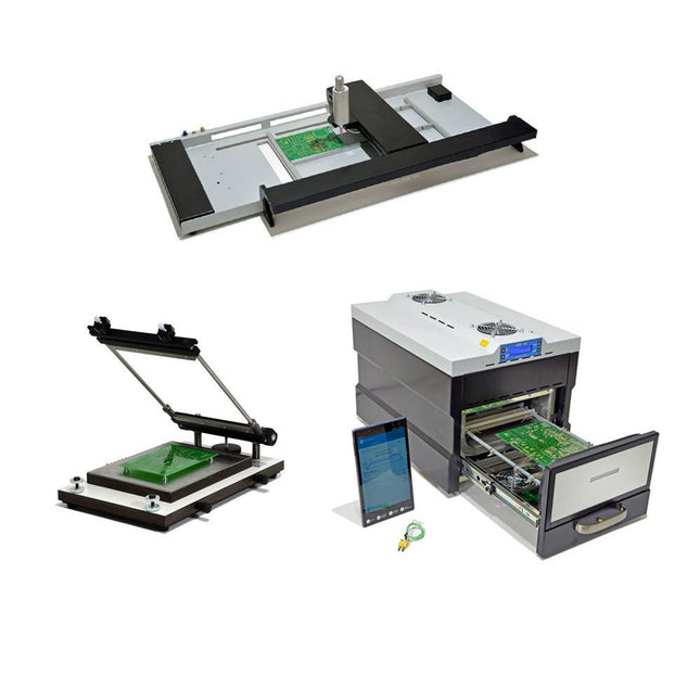
Paggen Werkzeugtechnik SMD Starter I – Production Line for Prototypes
The SMD Starter I prototype production line consists of the stencil printer TSD240, the SMD placement device PlaceMAN and the reflow oven 3LHR10. Stencil printer SD240 (+ Metal Squeegee 155 mm) Stencil size: max. 175 x 255 mm PCB size: max. 180 x 240 mm Size: 410 x 270 x 110 mm Weight: 6.7 kg incl. metal squeegee 155 mm incl. 8 magnets to hold the PCB, 6 of them with M3 grub screw Manual SMD pick-and-place device PlaceMAN for standard components incl. vacuum pump (without feeders, camera, monitor and dispenser) Equipped with smooth-running placement arm, placement head with one-hand operation, rotation of the Z-axis and automatic vacuum switch-off, incl. PCB holder, vacuum unit and 2 placement needles with rubber suction cups. Capacity of feeder (not included) 2x feeder cassette for 10 x 8 mm wheels left 4x feeder cassette for rod feeders for 5 rods each Further feeding systems are possible within the assembly area, e.g. strip-feeder plug-in system Dimensions Base unit (LxWxH): 765 x 390 x 210 mm With feeder cassette for 10 x 8 mm rolls (LxWxH): 765 x 390 x 210 mm With feeder cassette for 10 x 8 mm rolls and feeder cassette for rod feeder (LxWxH): 765 x 430 x 210 mm (height may vary due to rod length) With feeder cassette for 10 x 8 mm rolls incl. holder for 10 rolls and feeder cassette for rod feeder (LxWxH): 765 x 430 x 210 mm (height may vary due to rod length) Specifications Weight of basic unit: approx. 6 kg Axis travel (x,y,z): 470 x 230 x 15 mm Max. working area: 380 x 240 mm Max. PCB size: 230 x 360 mm Power supply: 230/12 V, 800 mA Power supply vacuum pump: 230 V, 6 W 3LHR10 Reflow Oven (programmable for lead-free soldering with manual drawer and tablet control) Reflow oven with IR and convection heating. Forced hot air convection ensures a uniform temperature profile throughout the chamber. After manually opening the door, the fans are turned on and the soldered PCB is quickly cooled. Small reflow oven with manual door Industry 4.0 ready, Bluetooth communication + tablet IR + convection heating Android application to connect to tablet or smartphone 100 different user programs Delivery content: 3LHR10, tablet with app, protective cover for tablet, 4 PCB holders, external thermocouple, manual at tablet Application Connect the oven to the power supply and connect the optionally available extraction system (3LFE10S) to the exhaust air nozzle. After the first turn on, the oven will search for a tablet or smartphone. When both are connected to the Android app, choose the programming of the oven. Here, programmable temperature and preheating time as well as temperature and other data are to be set. Register with the tablet to use the full scope of the software. If the oven is already programmed, the user can control the operation with buttons and display at the front panel. When the reflow process is complete, an audible signal sounds. A signal is also displayed on the tablet/smartphone. The drawer must now be opened manually. The Android application displays process status, time and temperature or other information. Specifications Power supply: 230 V, 50 Hz Maximum power: 3100 W Temperatures: 50-260°C Dimensions: 510 x 370 x 340 mm Maximum weight: 16 kg Grid dimensions: 350 x 220 mm Maximum dimensions of the printed circuit board: 300 x 200 mm Maximum component height on the PCB: 50 mm at the top, 30 mm at the bottom Scope of delivery Stencil printer TSD240 SMD placement device PlaceMAN Reflow oven 3LHR10
€ 6.549,00
Best Price
-

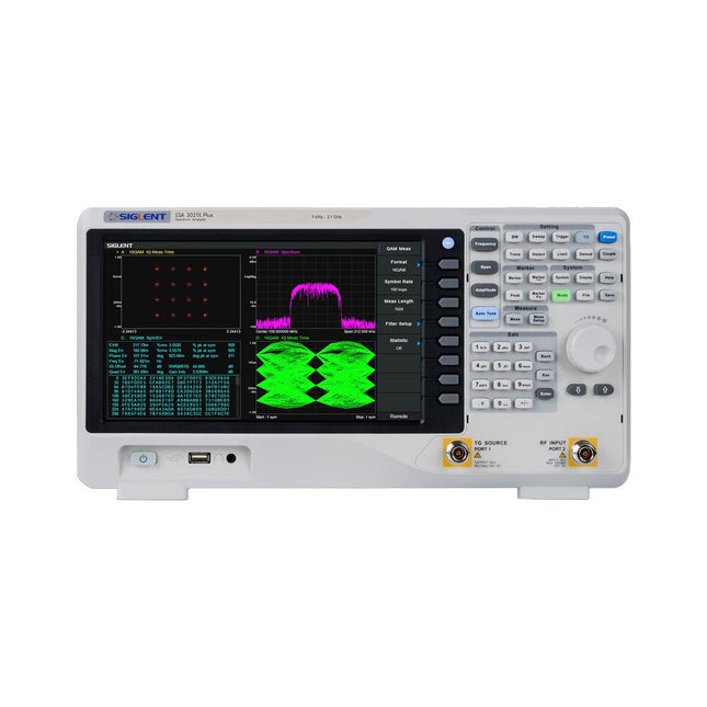
Siglent Siglent SSA3075X Plus Spectrum Analyzer (9 kHz – 7.5 GHz)
The Siglent SSA3075X Plus spectrum analyzer is a powerful and flexible tool for RF signal and network analysis. With a frequency range of 7.5 GHz, the analyzer delivers reliable automatic measurements and multiple modes of operation: spectrum analyzer the base, optional functions include RF power measurement, vector signal modulation analysis, reflection measurement, and EMI test. Applications include broadcast monitoring/evaluation, site surveying, S-parameter measurement, analog/digital modulation analysis, EMI pre-compliance test, research and development, education, production, and maintenance. Features Spectrum Analyzer Frequency Range from 9 kHz to 7.5 GHz –165 dBm/Hz Displayed Average Noise Level (Typ.) –98 dBc/Hz. @ 10 kHz Offset Phase Noise (1 GHz, Typ.) Level Measurement Uncertainty <0.7 dB (Typ.) 1 Hz Minimum Resolution Bandwidth (RBW) Preamplifier (Std.) Tracking Generator (incl. free of charge) Analog and Digital Signal Modulation Analysis Mode (opt.) Reflection Measurement Kit (opt.) EMI Filter and Quasi-Peak Detector Kit (opt.) Advanced Measurement Kit (opt.) 10.1-inch Multi-Touch Screen , Mouse and Keyboard supported Web Browser Remote Control on PC and Mobile Terminals and File Operation Specifications SSA3015X Plus SSA3021X Plus SSA3032X Plus SSA3075X Plus Frequency Range 9 kHz ~ 1.5 GHz 9 kHz ~ 2.1 GHz 9 kHz ~ 3.2 GHz 9 kHz ~ 7.5 GHz Resolution Bandwidth 1 Hz ~ 1 MHz 1 Hz ~ 1 MHz 1 Hz ~ 1 MHz 1 Hz ~ 3 MHz Phase Noise <–99 dBc/Hz <–98 dBc/Hz <–98 dBc/Hz <–98 dBc/Hz Total Amplitude Accuracy <1.2 dB <0.7 dB <0.7 dB <0.7 dB Display Average Noise Level –156 dBm/Hz –161 dBm/Hz –161 dBm/Hz –165 dBm/Hz Included Siglent SSA3075X Plus spectrum analyzer USB cable Power cord Quick start guide Downloads Datasheet Manual Documentation Firmware
€ 7.875,89
-
Siglent Siglent SSA3021X Plus Spectrum Analyzer (9 kHz – 2.1 GHz)
The Siglent SSA3021X Plus spectrum analyzer is a powerful and flexible tool for RF signal and network analysis. With a frequency range of 2.1 GHz, the analyzer delivers reliable automatic measurements and multiple modes of operation: spectrum analyzer the base, optional functions include RF power measurement, vector signal modulation analysis, reflection measurement, and EMI test. Applications include broadcast monitoring/evaluation, site surveying, S-parameter measurement, analog/digital modulation analysis, EMI pre-compliance test, research and development, education, production, and maintenance. Features Spectrum Analyzer Frequency Range from 9 kHz to 2.1 GHz –161 dBm/Hz Displayed Average Noise Level (Typ.) –98 dBc/Hz. @ 10 kHz Offset Phase Noise (1 GHz, Typ.) Level Measurement Uncertainty <0.7 dB (Typ.) 1 Hz Minimum Resolution Bandwidth (RBW) Preamplifier (Std.) Tracking Generator (incl. free of charge) Analog and Digital Signal Modulation Analysis Mode (opt.) Reflection Measurement Kit (opt.) EMI Filter and Quasi-Peak Detector Kit (opt.) Advanced Measurement Kit (opt.) 10.1-inch Multi-Touch Screen , Mouse and Keyboard supported Web Browser Remote Control on PC and Mobile Terminals and File Operation Specifications SSA3015X Plus SSA3021X Plus SSA3032X Plus SSA3075X Plus Frequency Range 9 kHz ~ 1.5 GHz 9 kHz ~ 2.1 GHz 9 kHz ~ 3.2 GHz 9 kHz ~ 7.5 GHz Resolution Bandwidth 1 Hz ~ 1 MHz 1 Hz ~ 1 MHz 1 Hz ~ 1 MHz 1 Hz ~ 3 MHz Phase Noise <–99 dBc/Hz <–98 dBc/Hz <–98 dBc/Hz <–98 dBc/Hz Total Amplitude Accuracy <1.2 dB <0.7 dB <0.7 dB <0.7 dB Display Average Noise Level –156 dBm/Hz –161 dBm/Hz –161 dBm/Hz –165 dBm/Hz Included Siglent SSA3021X Plus spectrum analyzer USB cable Power cord Quick start guide Downloads Datasheet Manual Documentation Firmware
€ 1.777,49
-

Siglent Siglent SDS2354X Plus 4-ch Oscilloscope (350 MHz)
Siglent's SDS2000X Plus series Digital Storage Oscilloscopes are available in bandwidths of 100 MHz, 200 MHz, and 350 MHz, have a maximum sample rate of 2 GSa/s, a maximum record length of 200 Mpts/ch, and up to 4 analog channels + 16 digital channels mixed-signal analysis ability. The SDS2000X Plus series employs Siglent’s SPO technology with a maximum waveform capture rate of up to 120,000 wfm/s (normal mode, up to 500,000 wfm/s in Sequence mode), 256-level intensity grading display function plus a color temperature display mode. It also employs an innovative digital trigger system with high sensitivity and low jitter. The trigger system supports multiple powerful triggering modes including serial bus triggering. History waveform recording, Sequence acquisition, Search and Navigate functions allow for extended waveform records to be captured, stored, and analyzed. An impressive array of measurement and math capabilities, options for a 50 MHz waveform generator, as well as serial decoding, mask test, bode plot, and power analysis are also features of the SDS2000X Plus. A 10-bit acquisition mode helps to satisfy applications that require more than 8-bit resolution. The large 10.1" capacitive touch screen supports multi-touch gestures, while the remote web control, mouse and external keyboard support greatly improve the operating efficiency of the SDS2000X Plus. Features 100 MHz, 200 MHz, 350 MHz (upgradable to 500 MHz) models Real-time sampling rate up to 2 GSa/s Record length up to 200 Mpts Serial bus triggering and decoder, supports I²C, SPI, UART, CAN, LIN, CAN FD, FlexRay, I²S and MIL-STD-1553B Provide 10 bit mode, Vertical and Horizontal Zoom Capacitive touch screen supports multi-touch gestures Siglent SDS2000X Plus Oscilloscopes SDS2102X Plus SDS2104X Plus SDS2204X Plus SDS2354X Plus Bandwidth 100 MHz 100 MHz 200 MHz 350 MHz Channels 2 4 4 4 Real-time sampling rate 2 GSa/s 2 GSa/s 2 GSa/s 2 GSa/s Capture rate 120,000 wfm/s 120,000 wfm/s 120,000 wfm/s 120,000 wfm/s Memory depth 200 Mpts/ch 200 Mpts/ch 200 Mpts/ch 200 Mpts/ch Included Siglent SDS2354X Plus Oscilloscope Passive probes Power cord USB cable Manual Downloads Datasheet Manual Quick guide Manual Firmware
€ 2.515,83
-
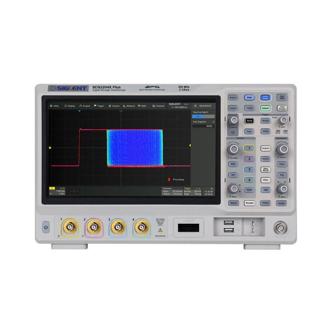
Siglent Siglent SDS2204X Plus 4-ch Oscilloscope (200 Mhz)
Siglent's SDS2000X Plus series Digital Storage Oscilloscopes are available in bandwidths of 100 MHz, 200 MHz, and 350 MHz, have a maximum sample rate of 2 GSa/s, a maximum record length of 200 Mpts/ch, and up to 4 analog channels + 16 digital channels mixed-signal analysis ability. The SDS2000X Plus series employs Siglent’s SPO technology with a maximum waveform capture rate of up to 120,000 wfm/s (normal mode, up to 500,000 wfm/s in Sequence mode), 256-level intensity grading display function plus a color temperature display mode. It also employs an innovative digital trigger system with high sensitivity and low jitter. The trigger system supports multiple powerful triggering modes including serial bus triggering. History waveform recording, Sequence acquisition, Search and Navigate functions allow for extended waveform records to be captured, stored, and analyzed. An impressive array of measurement and math capabilities, options for a 50 MHz waveform generator, as well as serial decoding, mask test, bode plot, and power analysis are also features of the SDS2000X Plus. A 10-bit acquisition mode helps to satisfy applications that require more than 8-bit resolution. The large 10.1’’ capacitive touch screen supports multi-touch gestures, while the remote web control, mouse and external keyboard support greatly improve the operating efficiency of the SDS2000X Plus. Features 100 MHz, 200 MHz, 350 MHz (upgradable to 500 MHz) models Real-time sampling rate up to 2 GSa/s Record length up to 200 Mpts Serial bus triggering and decoder, supports I²C, SPI, UART, CAN, LIN, CAN FD, FlexRay, I²S and MIL-STD-1553B Provide 10 bit mode, Vertical and Horizontal Zoom Capacitive touch screen supports multi-touch gestures Siglent SDS2000X Plus Oscilloscopes SDS2102X Plus SDS2104X Plus SDS2204X Plus SDS2354X Plus Bandwidth 100 MHz 100 MHz 200 MHz 350 MHz Channels 2 4 4 4 Real-time sampling rate 2 GSa/s 2 GSa/s 2 GSa/s 2 GSa/s Capture rate 120,000 wfm/s 120,000 wfm/s 120,000 wfm/s 120,000 wfm/s Memory depth 200 Mpts/ch 200 Mpts/ch 200 Mpts/ch 200 Mpts/ch Included Siglent SDS2204X Plus Oscilloscope Passive probes Power cord USB cable Manual Downloads Datasheet Manual Quick guide Manual Firmware
€ 1.838,23
-

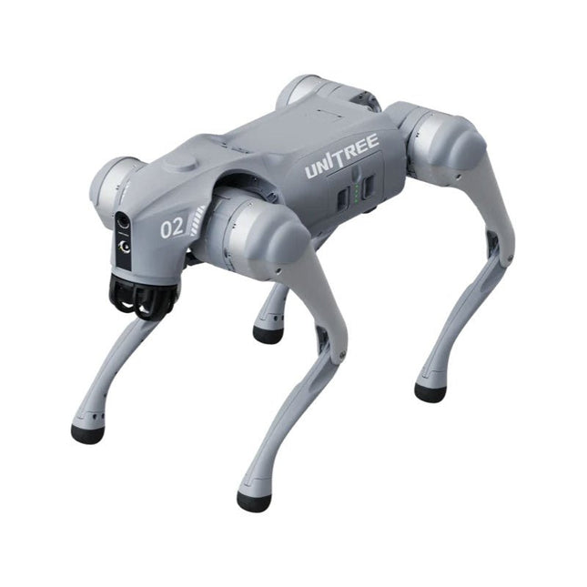
Unitree Unitree Go2 Edu Quadruped Robot
Temporary Delay in the Delivery of Unitree Robots Like many other suppliers, we are currently experiencing delays in the delivery of Unitree robots. A shipment from our supplier is currently held in customs, which has unfortunately led to later-than-planned deliveries for previously placed orders. We are actively working with our supplier to resolve this issue and expect more clarity soon, but at this time, we cannot provide any guarantees. Additionally, a new shipment is already on its way, though it will take some time to arrive. Since other suppliers are facing similar challenges, switching to a different provider is unlikely to result in a faster solution. Our top priority remains fulfilling existing orders. If you have any questions or would like to update your order, please do not hesitate to contact our customer service team. We will keep you informed of any further developments. Unitree Go2 series consists of quadruped robots for the research & development of autonomous systems in the fields of human-robot interaction (HRI), SLAM & transportation. Due to the four legs, as well as the 12DOF, this robot can handle a variety of different terrains. The Go2 comes with a perfected drive & power management system, which enables a speed (depending on the version) of up to 3.7 m/s or 11.88 km/h with an operating time of up to 4 hours. Furthermore, the motors have a torque of 45 N.m at the body/thighs and at the knees, which also allow jumps or backflips. Features Super Recognition System: 4D LIDAR L1 Max Running Speed: approx. 5 m/s Peak Joint Torque: approx. 45 N.m Wireless Module: WiFi 6/Bluetooth/4G Ultra-long battery Endurance: approx. 2-4 h (long battery life measured in real life) Intelligent Side-follow System: ISS 2.0 Specifications Tracking module: Remote-controlled or automatic tracking Front camera: Image tansmission Resolution 1280x720, FOV 120°, Ultra wide angle lens deliver rich clarity Front lamp: Brightly lights the way ahead 4D LiDAR L1: 360°x90° omnidirectional ultra-wide-angle scanning allows automatic avoidance with small blind spot and stable operation 12 knee joint motors: Strong and powerful, Beautiful and simple, Brandy new visual experience Intercom microphone: Effective communication with no scenario restrictions Self-retracting strap: Easy to carry and load things More stable, more powerful with advanced devices: 3D LiDAR, 4G ESIM Card, WiFi 6 with Dual-band, Bluetooth 5.2 for stable connection and remote control Powerful Computing Core: Motion controller, High-performance ARM processor, Improved Al algorithm processor, External ORIN NX/NANO Smart battery: Standard 8000 mAh battery, Long-endurance 15000 mAh battery, Protection from over-temp, overcharge and short-circuit Speaker for music play: Listen to music as your pleasure Unitree Go2 Variants The Go2 impresses not only with its technical capabilities, but also with a modern and slim design that gives it a futuristic look and makes it a real eye-catcher. The Go2 Air is specially designed for demos and presentations. With its basic features, it offers a solid basis for demonstrating the movement capabilities and functionality of a four-legged robot. Important: The Go2 Air is delivered without a controller. This can be purchased optionally. With a powerful 8-core high-performance CPU, the Pro and Edu offer impressive computing power required for complex tasks and demanding calculations. This enables faster and more efficient data processing and makes the Pro and Edu a reliable partner for your projects. From the Edu version onwards, the Go2 is programmable and opens up endless possibilities for developing and researching your own robotics applications. The Go2 is also able to handle a step height of up to 14 cm. This makes it an ideal tool for research, education and entry into the world of robotics. The Go2 Edu comes with a remote controller that gives you easy and intuitive control. You also get a docking station with impressive computing power of 100 TOPS, which is equipped with powerful AI algorithms and offers you technical support. Go2 Edu is equipped with a powerful 15000 mAh battery that gives it an impressive runtime of up to 4 hours. This long operating time allows the robot to carry out longer exploration missions and complete demanding tasks. Model Comparison Air Pro Edu/Edu Plus Dimensions (standing) 70 x 31 x 40 cm 70 x 31 x 40 cm 70 x 31 x 40 cm Dimensions (crouching) 76 x 31 x 20 cm 76 x 31 x 20 cm 76 x 31 x 20 cm Material Aluminium alloy + High strength engineering plastic Aluminium alloy + High strength engineering plastic Aluminium alloy + High strength engineering plastic Weight (with battery) about 15 kg about 15 kg about 15 kg Voltage 28~33.6 V 28~33.6 V 28~33.6 V Peaking capacity about 3000 W about 3000 W about 3000 W Payload ≈7 kg (MAX ~ 10 kg) ≈8 kg (MAX ~ 10 kg) ≈8 kg (MAX ~ 12 kg) Speed 0~2.5 m/s 0~3.5 m/s 0~3.7 m/s (MAX ~ 5 m/s) Max Climb Drop Height about 15 cm about 16 cm about 16 cm Max Climb Angle 30° 40° 40° Basic Computing Power N/A 8-core High-performance CPU 8-core High-performance CPU Aluminum knee joint motor 12 set 12 set 12 set Intra-joint circuit (knee) ✓ ✓ ✓ Joint Heat Pipe Cooler ✓ ✓ ✓ Range of Motion Body: −48~48° Body: −48~48° Body: −48~48° Thigh: −200°~90° Thigh: −200°~90° Thigh: −200°~90° Shank: −156°~−48° Shank: −156°~−48° Shank: −156°~−48° Max Torque N/A about 45 N.m about 45 N.m Super-wide-angle 3D LiDAR ✓ ✓ ✓ Wireless Vector Positioning Tracking Module N/A ✓ ✓ HD Wide-angle Camera ✓ ✓ ✓ Foot-end force sensor N/A N/A ✓ Basic Action ✓ ✓ ✓ Auto-scaling strap N/A ✓ N/A Upgraded Intelligent OTA ✓ ✓ ✓ RTT 2.0 Image Transmission ✓ ✓ ✓ App Basic Remote Control ✓ ✓ ✓ App Data Viewing ✓ ✓ ✓ App Graphical Programme ✓ ✓ ✓ Front Lamp (3 W) ✓ ✓ ✓ WiFi 6 with Dual-band ✓ ✓ ✓ Bluetooth 5.2/4.2/2.1 ✓ ✓ ✓ 4G Module N/A CN/GB CN/GB Voice Function N/A ✓ ✓ Music Playback N/A ✓ ✓ ISS 2.0 Intelligent side-follow system N/A ✓ ✓ Intelligent detection and avoidance ✓ ✓ ✓ Secondary development N/A N/A ✓ Manual controller Optional Optional ✓ High computing power module N/A N/A Edu: 40 TOPS computing power Edu Plus: 100 TOPS computing power NVIDIA Jetson Orin (optional) Smart Battery Standard (8000 mAh) Standard (8000 mAh) Long endurance (15000 mAh) Battery Life 1-2 h 1-2 h 2-4 h Charger Standard (33.6 V, 3.5 A) Standard (33.6 V, 3.5 A) Fast charge (33.6 V, 9 A) Included 1x Unitree Go2 Edu 1x Unitree Go2 Remote Controller 1x Unitree Go2 Battery (15000 mAh) 1x Unitree Docking station with 40 TOPS computing power Downloads Documentation iOS/Android apps GitHub
€ 12.499,00
Best Price
-
Unitree Unitree Go2 Air Quadruped Robot
Temporary Delay in the Delivery of Unitree Robots Like many other suppliers, we are currently experiencing delays in the delivery of Unitree robots. A shipment from our supplier is currently held in customs, which has unfortunately led to later-than-planned deliveries for previously placed orders. We are actively working with our supplier to resolve this issue and expect more clarity soon, but at this time, we cannot provide any guarantees. Additionally, a new shipment is already on its way, though it will take some time to arrive. Since other suppliers are facing similar challenges, switching to a different provider is unlikely to result in a faster solution. Our top priority remains fulfilling existing orders. If you have any questions or would like to update your order, please do not hesitate to contact our customer service team. We will keep you informed of any further developments. Unitree Go2 series consists of quadruped robots for the research & development of autonomous systems in the fields of human-robot interaction (HRI), SLAM & transportation. Due to the four legs, as well as the 12DOF, this robot can handle a variety of different terrains. The Go2 comes with a perfected drive & power management system, which enables a speed (depending on the version) of up to 3.7 m/s or 11.88 km/h with an operating time of up to 4 hours. Furthermore, the motors have a torque of 45 N.m at the body/thighs and at the knees, which also allow jumps or backflips. Features Super Recognition System: 4D LIDAR L1 Max Running Speed: approx. 5 m/s Peak Joint Torque: approx. 45 N.m Wireless Module: WiFi 6/Bluetooth/4G Ultra-long battery Endurance: approx. 2-4 h (long battery life measured in real life) Intelligent Side-follow System: ISS 2.0 Specifications Tracking module: Remote-controlled or automatic tracking Front camera: Image tansmission Resolution 1280x720, FOV 120°, Ultra wide angle lens deliver rich clarity Front lamp: Brightly lights the way ahead 4D LiDAR L1: 360°x90° omnidirectional ultra-wide-angle scanning allows automatic avoidance with small blind spot and stable operation 12 knee joint motors: Strong and powerful, Beautiful and simple, Brandy new visual experience Intercom microphone: Effective communication with no scenario restrictions Self-retracting strap: Easy to carry and load things More stable, more powerful with advanced devices: 3D LiDAR, 4G ESIM Card, WiFi 6 with Dual-band, Bluetooth 5.2 for stable connection and remote control Powerful Computing Core: Motion controller, High-performance ARM processor, Improved Al algorithm processor, External ORIN NX/NANO Smart battery: Standard 8000 mAh battery, Long-endurance 15000 mAh battery, Protection from over-temp, overcharge and short-circuit Speaker for music play: Listen to music as your pleasure Unitree Go2 Variants The Go2 impresses not only with its technical capabilities, but also with a modern and slim design that gives it a futuristic look and makes it a real eye-catcher. The Go2 Air is specially designed for demos and presentations. With its basic features, it offers a solid basis for demonstrating the movement capabilities and functionality of a four-legged robot. Important: The Go2 Air is delivered without a controller. This can be purchased optionally. With a powerful 8-core high-performance CPU, the Pro and Edu offer impressive computing power required for complex tasks and demanding calculations. This enables faster and more efficient data processing and makes the Pro and Edu a reliable partner for your projects. From the Edu version onwards, the Go2 is programmable and opens up endless possibilities for developing and researching your own robotics applications. The Go2 is also able to handle a step height of up to 14 cm. This makes it an ideal tool for research, education and entry into the world of robotics. The Go2 Edu comes with a remote controller that gives you easy and intuitive control. You also get a docking station with impressive computing power of 100 TOPS, which is equipped with powerful AI algorithms and offers you technical support. Go2 Edu is equipped with a powerful 15000 mAh battery that gives it an impressive runtime of up to 4 hours. This long operating time allows the robot to carry out longer exploration missions and complete demanding tasks. Model Comparison Air Pro Edu/Edu Plus Dimensions (standing) 70 x 31 x 40 cm 70 x 31 x 40 cm 70 x 31 x 40 cm Dimensions (crouching) 76 x 31 x 20 cm 76 x 31 x 20 cm 76 x 31 x 20 cm Material Aluminium alloy + High strength engineering plastic Aluminium alloy + High strength engineering plastic Aluminium alloy + High strength engineering plastic Weight (with battery) about 15 kg about 15 kg about 15 kg Voltage 28~33.6 V 28~33.6 V 28~33.6 V Peaking capacity about 3000 W about 3000 W about 3000 W Payload ≈7 kg (MAX ~ 10 kg) ≈8 kg (MAX ~ 10 kg) ≈8 kg (MAX ~ 12 kg) Speed 0~2.5 m/s 0~3.5 m/s 0~3.7 m/s (MAX ~ 5 m/s) Max Climb Drop Height about 15 cm about 16 cm about 16 cm Max Climb Angle 30° 40° 40° Basic Computing Power N/A 8-core High-performance CPU 8-core High-performance CPU Aluminum knee joint motor 12 set 12 set 12 set Intra-joint circuit (knee) ✓ ✓ ✓ Joint Heat Pipe Cooler ✓ ✓ ✓ Range of Motion Body: −48~48° Body: −48~48° Body: −48~48° Thigh: −200°~90° Thigh: −200°~90° Thigh: −200°~90° Shank: −156°~−48° Shank: −156°~−48° Shank: −156°~−48° Max Torque N/A about 45 N.m about 45 N.m Super-wide-angle 3D LiDAR ✓ ✓ ✓ Wireless Vector Positioning Tracking Module N/A ✓ ✓ HD Wide-angle Camera ✓ ✓ ✓ Foot-end force sensor N/A N/A ✓ Basic Action ✓ ✓ ✓ Auto-scaling strap N/A ✓ N/A Upgraded Intelligent OTA ✓ ✓ ✓ RTT 2.0 Image Transmission ✓ ✓ ✓ App Basic Remote Control ✓ ✓ ✓ App Data Viewing ✓ ✓ ✓ App Graphical Programme ✓ ✓ ✓ Front Lamp (3 W) ✓ ✓ ✓ WiFi 6 with Dual-band ✓ ✓ ✓ Bluetooth 5.2/4.2/2.1 ✓ ✓ ✓ 4G Module N/A CN/GB CN/GB Voice Function N/A ✓ ✓ Music Playback N/A ✓ ✓ ISS 2.0 Intelligent side-follow system N/A ✓ ✓ Intelligent detection and avoidance ✓ ✓ ✓ Secondary development N/A N/A ✓ Manual controller Optional Optional ✓ High computing power module N/A N/A Edu: 40 TOPS computing power Edu Plus: 100 TOPS computing power NVIDIA Jetson Orin (optional) Smart Battery Standard (8000 mAh) Standard (8000 mAh) Long endurance (15000 mAh) Battery Life 1-2 h 1-2 h 2-4 h Charger Standard (33.6 V, 3.5 A) Standard (33.6 V, 3.5 A) Fast charge (33.6 V, 9 A) Included 1x Unitree Go2 Air 1x Unitree Go2 Battery (8000 mAh) Downloads Documentation iOS/Android apps GitHub
€ 2.650,00
Best Price
-
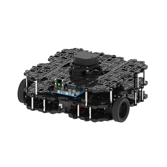
Robotis Robotis TurtleBot3 Waffle Pi (incl. Raspberry Pi 4)
World’s Most Popular ROS Platform TurtleBot is the most popular open source robot for education and research. The new generation TurtleBot3 is a small, low cost, fully programmable, ROS based mobile robot. It is intended to be used for education, research, hobby and product prototyping. Affordable Cost TurtleBot was developed to meet the cost-conscious needs of schools, laboratories and companies. TurtleBot3 is the most affordable robot among the SLAM-able mobile robots equipped with a 360° Laser Distance Sensor LDS-01. ROS Standard The TurtleBot brand is managed by Open Robotics, which develops and maintains ROS. Nowadays, ROS has become the go-to platform for all the roboticists around the world. TurtleBot can be integrated with existing ROS-based robot components, but TurtleBot3 can be an affordable platform for whom want to get started learning ROS. Extensibility TurtleBot3 encourages users to customize its mechanical structure with some alternative options: open source embedded board (as a control board), computer and sensors. TurtleBot3 Waffle Pi is a two-wheeled differential drive type platform but it is able to be structurally and mechanically customized in many ways: Cars, Bikes, Trailers and so on. Extend your ideas beyond imagination with various SBC, sensors and motors on a scalable structure. Modular Actuator for Mobile Robot TurtleBot3 is able to get a precise spatial data by using 2 DYNAMIXEL’s in the wheel joints. DYNAMIXEL XM series can be operated by one of 6 operating modes (XL series: 4 operating modes): Velocity control mode for wheels, Torque control mode or Position control mode for joint, etc. DYNAMIXEL can be used even to make a mobile manipulator which is light but can be precisely controlled with velocity, torque and position control. DYNAMIXEL is a core component that makes TurtleBot3 perfect. It is easy to assemble, maintain, replace and reconfigure. Open Control Board for ROS The control board is open-sourced in hardware wise and in software wise for ROS communication. The open source control board OpenCR1.0 is powerful enough to control not only DYNAMIXEL’s but also ROBOTIS sensors that are frequently being used for basic recognition tasks in cost effective way. Various sensors such as Touch sensor, Infrared sensor, Color sensor and a handful more are available. The OpenCR1.0 has an IMU sensor inside the board so that it can enhance precise control for countless applications. The board has 3.3 V, 5 V, 12 V power supplies to reinforce the available computer device lineups. Open Source The hardware, firmware and software of TurtleBot3 are open source which means that users are welcomed to download, modify and share source codes. All components of TurtleBot3 are manufactured with injection molded plastic to achieve low cost, however, the 3D CAD data is also available for 3D printing. Specifications Maximum translational velocity 0.26 m/s Maximum rotational velocity 1.82 rad/s (104.27 deg/s) Maximum payload 30 kg Size (L x W x H) 281 x 306 x 141 mm Weight (+ SBC + Battery + Sensors) 1.8 kg Threshold of climbing 10 mm or lower Expected operating time 2h Expected charging time 2h 30m SBC (Single Board Computers) Raspberry Pi 4 (2 GB RAM) MCU 32-bit ARM Cortex-M7 with FPU (216 MHz, 462 DMIPS) Remote Controller RC-100B + BT-410 Set (Bluetooth 4, BLE) Actuator XL430-W210 LDS (Laser Distance Sensor) 360 Laser Distance Sensor LDS-01 or LDS-02 Camera Raspberry Pi Camera Module v2.1 IMU Gyroscope 3 AxisAccelerometer 3 Axis Power connectors 3.3 V/800 mA5 V/4 A12 V/1 A Expansion pins GPIO 18 pinsArduino 32 pin Peripheral 3x UART, 1x CAN, 1x SPI, 1x I²C, 5x ADC, 4x 5-pin OLLO DYNAMIXEL ports 3x RS485, 3x TTL Audio Several programmable beep sequences Programmable LEDs 4x User LED Status LEDs 1x Board status LED1x Arduino LED1x Power LED Buttons and Switches 2x Push buttons, 1x Reset button, 2x Dip switch Battery Lithium polymer 11.1 V 1800 mAh / 19.98 Wh 5C PC connection USB Firmware upgrade via USB / via JTAG Power adapter (SMPS) Input: 100-240 VAC 50/60 Hz, 1.5 A @maxOutput: 12 VDC, 5 A Downloads ROS Robot Programming GitHub E-Manual Community
€ 1.879,00
Best Price
-
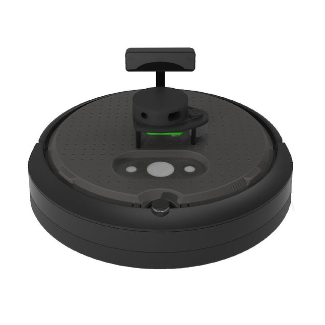
Clearpath Robotics Clearpath Robotics TurtleBot 4 Lite
TurtleBot 4 is the next-generation of the world’s most popular open source robotics platform for education and research, offering better computing power, better sensors and a world class user experience at an affordable price point.TurtleBot 4 Lite is equipped with an iRobot Create 3 mobile base, a powerful Raspberry Pi 4 running ROS 2, OAK-D spatial AI stereo camera, 2D LiDAR and more. All components have been seamlessly integrated to deliver an out-of-the-box development and learning platform.Specifications Base platform iRobot Create 3 Wheels (Diameter) 72 mm Ground Clearance 4.5 mm On-board Computer Raspberry Pi 4 (4 GB) Maximum linear velocity 0.31 m/s in safe mode0.46 m/s without safe mode Maximum angular velocity 1.90 rad/s Maximum payload 9 kg Operation time 2h 30m – 4h depending on load Charging time 2h 30m Lidar RPLIDAR A1M8 Camera OAK-D-Lite User Power VBAT @1.9 A5 V @ Low current3.3 V @ Low current USB Expansion 2x USB 2.0 (Type A)2x USB 3.0 (Type A) Programmable LEDs Create 3 Lightring Buttons and Switches 2x Create 3 User buttons1x Create 3 Power Button Battery 26 Wh Lithium Ion (14.4 V nominal) Charging Dock Included Size (L x W x H) 342 x 339 x 192 mm Weight 3.3 kg DownloadsUser Manual
€ 1.699,00
Best Price


