The HuskyLens AI Camera intuitive design allows the user to control different aspects of the camera just by pressing buttons. You can start and stop learning new objects and even switch between algorithms from the device.
To further reduce the need to be connected to a PC the HuskyLens AI Camera comes with a 2-inch display so you can see what's going on in real time.
Specifications
Processor: Kendryte K210
Image Sensor: OV2640 (2.0 Megapixel Camera)
Supply Voltage: 3.3~5.0 V
Current Consumption (TYP): 320 mA @ 3.3 V, 230 mA @ 5.0 V (face recognition mode; 80% backlight brightness; fill light off)
Connection Interface: UART, I²C
Display: 2.0-inch IPS screen with 320x240 resolution
Built-in Algorithms: Face Recognition, Object Tracking, Object Recognition, Line Tracking, Color Recognition, Tag Recognition
Dimension: 52 x 44.5 mm (2.05 x 1.75')
Included
1x HuskyLens Mainboard
6x M3 Screws
6x M3 Nuts
1x Small Mounting Bracket
1x Heightening Bracket
1x Gravity 4-Pin Sensor Cable
The SparkFun GPS-RTK2 raises the bar for high-precision GPS and is the latest in a line of powerful RTK boards featuring the ZED-F9P module from u-blox. The ZED-F9P is a top-of-the-line module for high accuracy GNSS and GPS location solutions, including RTK capable of 10 mm, three-dimensional accuracy. With this board, you will be able to know where your (or any object's) X, Y, and Z location is within roughly the width of your fingernail! The ZED-F9P is unique in that it is capable of both rover and base station operations. Utilizing our handy Qwiic system, no soldering is required to connect it to the rest of your system. However, we still have broken out 0.1'-spaced pins if you prefer to use a breadboard.
We've even included a rechargeable backup battery to keep the latest module configuration and satellite data available for up to two weeks. This battery helps 'warm-start' the module decreasing the time-to-first-fix dramatically. This module features a survey-in mode allowing the module to become a base station and produce RTCM 3.x correction data.
The number of configuration options of the ZED-F9P is incredible! Geofencing, variable I²C address, variable update rates, even the high precision RTK solution can be increased to 20 Hz. The GPS-RTK2 even has five communications ports which are all active simultaneously: USB-C (which enumerates as a COM port), UART1 (with 3.3 V TTL), UART2 for RTCM reception (with 3.3V TTL), I²C (via the two Qwiic connectors or broken out pins), and SPI.
Sparkfun has also written an extensive Arduino library for u-blox modules to easily read and control the GPS-RTK2 over the Qwiic Connect System. Leave NMEA behind! Start using a much lighter weight binary interface and give your microcontroller (and its one serial port) a break. The SparkFun Arduino library shows how to read latitude, longitude, even heading and speed over I²C without the need for constant serial polling.
Features
Concurrent reception of GPS, GLONASS, Galileo and BeiDou
Receives both L1C/A and L2C bands
Voltage: 5 V or 3.3 V, but all logic is 3.3 V
Current: 68 mA - 130 mA (varies with constellations and tracking state)
Time to First Fix: 25 s (cold), 2 s (hot)
Max Navigation Rate:
PVT (basic location over UBX binary protocol) - 25 Hz
RTK - 20 Hz
Raw - 25 Hz
Horizontal Position Accuracy:
2.5 m without RTK
0.010 m with RTK
Max Altitude: 50k m
Max Velocity: 500 m/s
Weight: 6.8 g
Dimensions: 43.5 x 43.2 mm
2x Qwiic Connectors
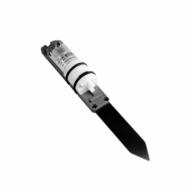
The M5Stack Watering Unit integrates water pump and measuring plates for soil moisture detection and pump water control. It can be used for intelligent plant breeding scenarios and can easily achieve humidity detection and Irrigation control. The measurement electrode plate uses the capacitive design, which can effectively avoid the corrosion problem of the electrode plate in actual use compared with the resistive electrode plate.
Features
Capacitive measuring plate (corrosion resistant)
Integrated 5 W power water pump
LEGO compatible holes
Applications
Plant cultivation
Soil moisture detection
Smart irrigation
Included
1x Watering Unit
2x Suction pipe
1x HY2.0-4P cable
Pump power
5 W
Weight
78 g
Dimensions
192.5 x 24 x 33 mm
YDLIDAR SDM18 is a high-performance single-point LiDAR. Based on the principle of ToF, it is equipped with related optics, electricity, and algorithm design to achieve high-precision laser distance measurement and outputting high frame rate point cloud data of the scanning environment. It can be used for UAV alt-hold, robot obstacle avoidance and navigation, etc.
Specifications
High Ranging frequency: 50-250 Hz
Range Distance: 0.2-18 m
FDA Class I eye safety standard
Support UART and I²C interfaces
Dimensions: 21 x 15 x 7.87 mm
Weight: 1.35 g
Applications
UAV alt-hold and obstacle avoidance
Robot obstacle avoidance
Intelligent equipment obstacle avoidance
Navigation and obstacle avoidance of home service robots / robot vacuum cleaners
Downloads
Datasheet
User Manual
Development Manual
SDK
Tool
ROS
The Grove DHT11 Temperature & Humidity Sensor is a high-quality, low-cost digital temperature, and humidity sensor based on the DHT11 module. It is the most common temperature and humidity module for Arduino and Raspberry Pi. It is widely favored by hardware enthusiasts for its many advantages such as low power consumption and excellent long-term stability. Relatively high measurement accuracy can be obtained at a very low cost. The single-bus digital signal is output through the built-in ADC, which saves the I/O resources of the control board. Features Dimensions: 40 x 20 x 8 mm Weight: 10 g Battery: Exclude Input Voltage: 3.3 V & 5 V Measuring Current: 1.3 mA- 2.1 mA Measuring Humidity Range: 5% - 95% RH Measuring Temperature Range: -20 ℃ - 60 ℃
We've provided a Qwiic connector to connect to the I²C data lines easily, but you will also need to connect to two additional lines. This board is tiny, measuring 25.4 mm x 12.7 mm, which means it will fit nicely on your finger without all the bulk. The MAX30101 does all the sensing by utilizing its internal LEDs to bounce light off the arteries and arterioles in your finger's subcutaneous layer and sensing how much light is absorbed with its photodetectors. This is known as photoplethysmography. This data is passed onto and analyzed by the MAX32664, which applies its algorithms to determine heart rate and blood oxygen saturation (SpO2). SpO2 results are reported as the percentage of hemoglobin that is saturated with oxygen. It also provides useful information such as the sensor's confidence in its reporting and a handy finger detection data point. To get the most out of the sensor, Sparkfun has written an Arduino Library to make it easy to adjust all the possible configurations. Features SparkFun Pulse Oximeter and Heart Rate Sensor MAX30101 and MAX32664 sensor and sensor hub Qwiic connectors for power and I²C interface I²C Address: 0x55 MAX30101 - Pulse Oximeter and Heart-Rate Sensor Heart-Rate Monitor and Pulse Oximeter Sensor in LED Reflective Solution Integrated Cover Glass for Optimal, Robust Performance Ultra-Low Power Operation for Mobile Devices Fast Data Output Capability Robust Motion Artifact Resilience MAX32664 - Ultra-Low Power Biometric Sensor Hub Biometric Sensor Hub Solution Finger-Based Algorithms Measure Pulse Heart Rate and Pulse Blood Oxygenation Saturation (SpO2) Both Raw and processed data are available. Basic Peripheral mix optimizes size and performance.
The VL53L1X from STMicroelectronics uses a VCSEL (Vertical Cavity Surface Emitting Laser) to emit an Infrared laser to time the reflection to the target. That means that you will be able to measure the distance to an object from 40mm to 4m away with millimeter resolution! To make it even easier to get your readings, all communication is enacted exclusively via I²C, utilizing our handy Qwiic system, so no soldering is required to connect it to the rest of your system. However, we still have broken out 0.1”-spaced pins in case you prefer to use a breadboard. Each VL53L1X sensor features a precision to be 1mm with an accuracy around +/-5mm, and a minimum read distance of this sensor is 4cm. The field of view for this little breakout is fairly narrow at 15°-27° with a read rate of up to 50Hz. Make sure to power this board appropriately since it will need 2.6V-3.5V to operate. Lastly, please be sure to remove the protective sticker on the VL53L1X before use otherwise it will, most assuredly, throw off your readings. Features Operating Voltage: 2.6V-3.5V Power Consumption: 20 mW @10Hz Measurement Range: ~40mm to 4,000mm Resolution: +/-1mm Light Source: Class 1 940nm VCSEL 7-bit unshifted I²C Address: 0x29 Field of View: 15° - 27° Max Read Rate: 50Hz
The NEO-M8U module is a 72-channel u-blox M8 engine GNSS receiver, meaning it can receive signals from the GPS, GLONASS, Galileo, and BeiDou constellations with ~2.5-meter accuracy. The module supports the concurrent reception of three GNSS systems. The combination of GNSS and integrated 3D sensor measurements on the NEO-M8U provide accurate, real-time positioning rates of up to 30Hz.
Compared to other GPS modules, this breakout maximizes position accuracy in dense cities or covered areas. Even under poor signal conditions, continuous positioning is provided in urban environments and is also available during complete signal loss (e.g. short tunnels and parking garages). With UDR, position begins as soon as power is applied to the board, even before the first GNSS fix is available! Lock time is further reduced with an on-board rechargeable battery; you'll have backup power enabling the GPS to get a hot lock within seconds!
Additionally, this u-blox receiver supports I²C (u-blox calls this Display Data Channel), making it perfect for the Qwiic compatibility, so we don't have to use up our precious UART ports. Utilizing our handy Qwiic system, no soldering is required to connect it to the rest of your system. However, we still have broken out 0.1'-spaced pins if you prefer to use a breadboard.
U-blox based GPS products are configurable using the popular but dense, windows program called u-centre. Plenty of different functions can be configured on the NEO-M8U: baud rates, update rates, geofencing, spoofing detection, external interrupts, SBAS/D-GPS, etc. All of this can be done within the SparkFun Arduino Library!
The SparkFun NEO-M8U GPS Breakout is also equipped with an on-board rechargeable battery that provides power to the RTC on the NEO-M8U. This reduces the time-to-first fix from a cold start (~26s) to a hot start (~1.5s). The battery will maintain RTC and GNSS orbit data without being connected to power for plenty of time.
Features
Integrated U.FL connector for use with an antenna of your choice
72-Channel GNSS Receiver
2.5 m Horizontal Accuracy
30 Hz Max Update Rate
Time-To-First-Fix:
Cold: 26 s
Hot: 1.5 s
Max Altitude: 50,000 m
Max G: ≤4
Max Velocity: 500 m/s
Velocity Accuracy: 0.5m/s
Heading Accuracy: 1 degree
Built-In Accelerometer and Gyroscope
Time Pulse Accuracy: 30 ns
3.3 V VCC and I/O
Current Consumption: ~29 mA Continuous Tracking, Default Concurrent Mode
Software Configurable
Geofencing
Odometer
Spoofing Detection
External Interrupt
Pin Control
Low Power Mode
Many others!
Supports NMEA, UBX, and RTCM protocols over UART or I²C interfaces
Features
Four fully independent sensor elements on one package.
The ability to detect a variety of gases, besides Carbon monoxide (CO), Nitrogen dioxide (NO2), Ethyl alcohol(C2H5CH), Volatile Organic Compounds (VOC), etc.
Qualitative detecting, rather than quantitative.
Compact size for easy deployment.
Included
1x Multichannel gas sensor board
1x Grove cable
The LSN50 wireless part is based on SX1276/SX1278 allows the user to send data and reach extremely long ranges at low data rates. It provides ultra-long range spread spectrum communication and high interference immunity whilst minimizing current consumption. It targets professional wireless sensor network applications such as irrigation systems, smart metering, smart cities, smartphone detection, building automation, and so on.
The LSN50 MCU part uses STM32l0x chip from ST, STML0x is the ultra-low-power STM32L072xx microcontrollers incorporate the connectivity power of the universal serial bus (USB 2.0 crystal-less) with the high-performance ARM® Cortex®-M0+ 32-bit RISC core operating at a 32 MHz frequency, a memory protection unit (MPU), high-speed embedded memories (192 Kbytes of Flash program memory, 6 Kbytes of data EEPROM and 20 Kbytes of RAM) plus an extensive range of enhanced I/Os and peripherals.
The LSN50 is an open-source product, it is based on the STM32Cube HAL drivers and lots of libraries can be found on the STM site for rapid development.
Features
STM32L072CZT6 MCU
SX1276/78 LoRa Wireless Modem
Pre-load with ISP bootloader
I2C,LPUSART1,USB
18 x Digital I/Os
2 x 12bit ADC; 1 x 12bit DAC
MCU wakes up by UART or Interrupt
LoRa™ Modem
Preamble detection
Baud rate configurable
LoRaWAN 1.0.2 Specification
Software base on STM32Cube HAL drivers
Open-source hardware / software
IP66 Waterproof Enclosure
Ultra-Low power consumption
AT Commands to setup parameters
4000mAh Battery for Long term use
Applications
Wireless Alarm and Security Systems
Home and Building Automation
Automated Meter Reading
Industrial Monitoring and Control
Long-range Irrigation Systems
LoRa Spec
168 dB maximum link budget.
+20 dBm - 100 mW constant RF output vs.
+14 dBm high-efficiency PA.
Programmable bit rate up to 300 kbps.
High sensitivity: down to -148 dBm.
Bullet-proof front end: IIP3 = -12.5 dBm.
Excellent blocking immunity.
Low RX current of 10.3 mA, 200 nA register retention.
Fully integrated synthesizer with a resolution of 61 Hz.
FSK, GFSK, MSK, GMSK, LoRaTM and OOK modulation.
Built-in bit synchronizer for clock recovery.
Preamble detection.
127 dB Dynamic Range RSSI.
Automatic RF Sense and CAD with ultra-fast AFC.
Packet engine up to 256 bytes with CRC.
Built-in temperature sensor and low battery indicator.
MCU Spec
MCU: STM32L072CZT6
Flash: 192KB
SRAM: 20KB
EEPROM: 6KB
Clock Speed: 32Mhz
Absolute Maximum Ratings
VCC: 0.5 V ~ 3.9 V
Operating Tempature: -40°C ~ 85°C
I/O pins: 0.5 V ~ VCC+0.5 V
Common DC Characteristics
Supply Voltage: 1.8 V ~ 3.6 V
Operating Tempature: -40°C ~ 85°C
I/O pins: STM32L072CZT6 datasheet
Power Consumption
STOP Mode: 2.7 μA @ 3.3 V
RX Mode: 7.2 mA
TX Mode: 125 mA@ 20 dbm
Battery
Li/SOCI2 unchargable battery
Capacity: 4000 mAh
Self Discharge: < 1% / Year @ 25°C
Max continuously current: 130 mA
Max boost current: 2 A, 1 second
YDLIDAR T-mini Pro is a 360-degrees 2D LiDAR based on the principle of ToF. It is equipped with related optics, electricity, and algorithm design to achieve high-precision laser distance measurement, while measuring the distance, the mechanical structure rotates 360 degrees to continuously obtain angle information, thereby realizing 360 degrees scanning distance measurement and outputting point cloud data of the scanning environment.
Features
It adopts the mature ToF detection principle, it can be easy to integrate into the whole device with a small size, bringing the robot a 360° two-dimensional environment with strong stability and high precision.
6-12 Hz self-adaptive scanning frequency, the speed can be adjusted independently according to functional needs. The mechanical structure rotates 360°, continuously obtains angle information, scans and measures in all directions, and outputs point cloud.
Smaller appearance and lower power consumption, which can greatly optimize the spatial structure of application products and are suitable for more scenarios.
The brushless motor operates efficiently and has a longer lifespan of 10,000 hours.
Specifications
Range distance: 0.02-12 m
Range frequency: 4000 Hz
Angle resolution: 0.54 degrees
Scan frequency: 6-12 Hz
Scan angle: 360 degrees
Interface: UART
Applications
Robot navigation and obstacle avoidance
Robot ROS teaching and research
Regional security
Environmental scanning and 3D reconstruction
Navigation and obstacle avoidance of home service robots/ robot vacuum cleaners
Downloads
Datasheet
Manual
Development Manual
SDK
Tool
ROS
This camera adopts binocular structured light 3D imaging technology to obtain depth images and realize the function of depth information modeling. It is equipped with a dedicated depth computing chip and is specially optimized for robot obstacle avoidance.
The camera is compact in size, easy to integrate, with USB2.0 standard output interface, providing users with a high degree of flexibility. It can be adapted to complex environments such as all-black environment, indoors with strong light or weak light, backlight or smooth light, even semi-outdoors, which has a wide range of applications.
Features
Offers 1280 x 920 high-resolution image output
Uses the binocular structured light 3D imaging technology
Fearless ambient light interference
Deep calculation processors use high-performance dedicated chips
USB2.0 standard output interface
Specifications
Detection distance: 20-250 cm
Accuracy Error: <1.5 cm
Resolution: 1280 x 920 Pixel
HFOV: 78 ±3°
VFOV: 60 ±3°
Power: 1.5 W
Active Light Source: Spectrum: 830-850 nm | Power: <1.5 W
Dust-proof and Waterproof: IP65
ESD: Contact Discharge: ±8 KV | Antiaircraft: ±12 KV
Interface: USB2.0
Operating Temperature: -10~50°C
Operating Humidity: 0~80 RH
Storage Temperature: -20~80°C
Weight: 96 g
Downloads
Datasheet
User Manual
Development Manual
SDK
Tool
ROS
Maker Line is a line sensor with 5 x IR sensors array that is able to track line from 13 mm to 30 mm width. The sensor calibration is also simplified. There is no need to adjust the potentiometer for each IR sensor. You just have to press the calibrate button for 2 seconds to enter calibration mode. Afterwards you need to sweep the sensors array across the line, press the button again and you are good to go. The calibration data is saved in EEPROM and it will stay intact even if the sensor has been powered off. Thus, calibration only needs to be carried out once unless the sensor height, line color or background color has changed. Maker Line also supports dual outputs: 5 x digital outputs for the state of each sensor independently, which is similar to conventional IR sensor, but you get the benefit of easy calibration, and also one analog output, where its voltage represents the line position. Analog output also offers higher resolution compared to individual digital outputs. This is especially useful when high accuracy is required while building a line following robot with PID control. Features Operating Voltage: DC 3.3 V and 5 V compatible (with reverse polarity protection) Recommended Line Width: 13 mm to 30 mm Selectable line color (light or dark) Sensing Distance (Height): 4 mm to 40 mm (Vcc = 5 V, Black line on white surface) Sensor Refresh Rate: 200 Hz Easy calibration process Dual Output Types: 5 x digital outputs represent each IR sensor state, 1 x analog output represents line position. Support wide range of controllers such as Arduino, Raspberry Pi etc. Documentation Datasheet Tutorial: Building A Low-Cost Line Following Robot
After power on, YDLIDAR G4 start rotating and scanning the environment around it. The scanning distance is 16 m and the device offers a scanning rate of 9,000 times per second.
It makes detailed examinations of its environment and can locate the smallest of objects surrounding it. Featuring a high-precision brushless motor and encoder disc mounted on bearings, it rotates smoothly and has a service life of up to 500,000 hours of operation.
The G4 is an inexpensive solution for projects that require obstacle detection, obstacle avoidance, and/or simultaneous localization and mapping (SLAM). All YDLIDAR products are ROS ready.
Features
360 degree 2D range scanning
Stable performance, high precision
16 m range
Strong resistance to environmental light interference
Brushless motor drive, stable performance
FDA Laser safety standard Class I
360 degree omnidirectional scanning, 5-12 Hz adaptive scanning frequency
OptoMagnetic technology
Wireless data communication
Scanning rate of 9000 Hz
Downloads
Datasheet
User Manual
Development Manual
SDK
Tool
ROS
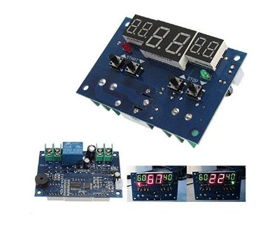
The Intelligent Digital Thermostat Temperature Controller is a small switch controller (77x51mm) which allows you to create your own thermostat. With its NTC Sensor and its LED displays, you are able to switch up to 10A 220V depending on the measured temperature.
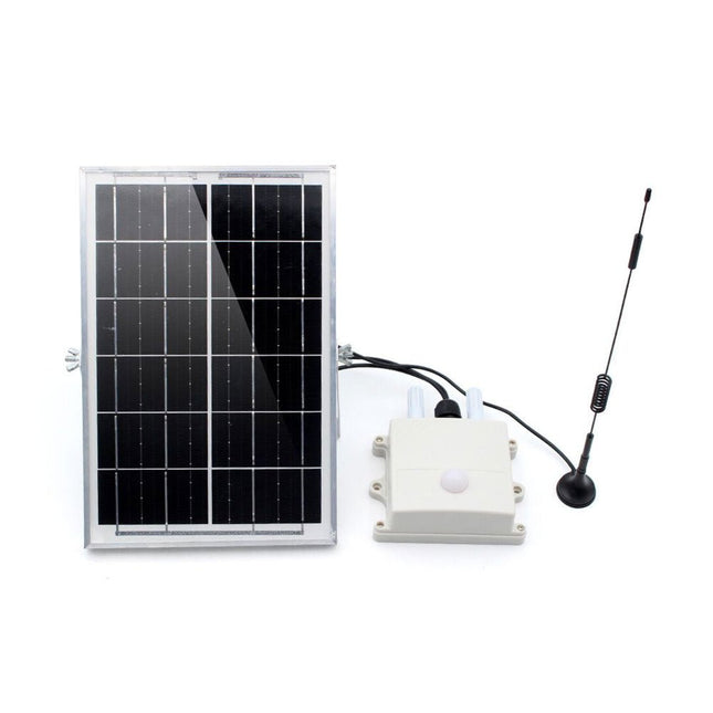
This air monitor is specifically used for monitoring greenhouses. It detects:
Air temperature & Humidity
CO2 concentration
Light intensity
Then transmit the data via LoRa P2P to the LoRa receiver (on your desk in the room) so that the user can monitor the field status or have it recorded for long-term analysis.
This module monitors the greenhouse field status and sends all sensor data regularly via LoRa P2P in Jason format. This LoRa signal can be received by the Makerfabs LoRa receiver and thus displayed/recorded/analyzed on the PC. The monitoring name/data cycle can be set with a phone, so it can be easily implemented into the file.
This air monitor is powered by an internal LiPo battery charged by a solar panel and can be used for at least 1 year with the default setting (cycle 1 hour).
Features
ESP32S3 module onboard with the WiFi and Bluetooth
Ready to use: Power it on directly to use
Module name/signal interval settable easily by phone
IP68 water-proof
Temperature: -40°C~80°C, ±0.3
Humidity: 0~100% moisture
CO2: 0~1000 ppm
Light intensity: 1-65535 lx
Communication distance: Lora: >3 km
1000 mAh battery, charger IC onboard
Solar panel 6 W, ensure system works
Downloads
Manual
BH1750 Datasheet
SGP30 Datasheet
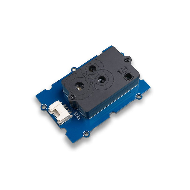
Features NDIR CO2 sensor technology: embedded with Sensirion SCD30 Multi-function: Integrates temperature and humidity sensor on the same sensor module High precision and wide measurement accuracy: ±(30 ppm + 3%) between 400 ppm to 10000 ppm Superior stability: Dual-channel detection Easy project operation: Digital interface I²C, Breadboard-friendly, Grove-compatible Best performance-to-price ratio Application Ideas Air Purifier Environmental Monitoring Plant Environmental Monitoring system Arduino weather station
Grove 3-Axis Digital Accelerometer (LIS3DHTR) is a low-cost 3-Axis accelerometer in a bundle of Grove products. It is based on the LIS3DHTR chip which provides multiple ranges and interfaces selection. You can never believe that such a tiny 3-Axis accelerometer can support I²C, SPI, and ADC GPIO interfaces, which means you can choose any way to connect with your development board. Besides, this accelerometer can also monitor the surrounding temperature to tune the error caused by it. Features Measurement range: ±2g, ±4g, ±8g, ±16g, multiple ranges selection. Multiple interfaces option: Grove I²C interface, SPI interface, ADC interface. Temperature adjustable: able to adjust and tune the error caused by temperature. 3/5V power supply Specifications Power Supply 3/5V Interfaces IC/SPI/GPIO ADC I²C address Default 0x19, can be changed to 0x18 when connecting SDO Pin with GND ADC GPIO Power input 0-3.3V Interruption An interruption Pin reserved SPI Mode set up Connect the CS Pin with GND Included 1x Grove 3-Axis Digital Accelerometer (LIS3DHTR) 1x Grove cable Downloads LIS3DHTR Datasheet Hardware schematic Arduino Library
This module has an ultrasonic transmitter and an ultrasonic receiver so you can consider it as an ultrasonic transceiver. Familiar with sonar, when the 40 kHz ultrasonic wave generated by the transmitter encounters the object, the sound wave will be emitted back, and the receiver can receive the reflected ultrasonic wave. It is only necessary to calculate the time from the transmission to the reception, and then multiply the speed of the sound in the air (340 m/s) to calculate the distance from the sensor to the object. Features 3.3V / 5V compatible, wide voltage level: 3.2V~5.2V Only 3 pins are needed, save I/O resources Wide measurement range: 3cm ~ 350cm Plug and play with Grove connector Applications Distance measurement Ultrasonic detector Proximity alarm Smart car Technical Specifications Dimensions 50 mm x 25 mm x 16 mm Weight 17 g Battery Exclude Measuring range 3 cm - 350 cm Operating voltage DC 3.2 V ~ 5.2 V Operating current 8 mA Ultrasonic frequency 40 kHz Connector 1 x Grove Output PWM
Want to make a UV detector to know the UV index when you are under the sun? Grove Sunlight Sensor is a multi-channel digital light sensor, which has the ability to detect UV-light, visible light and infrared light. This device is based on SI1151, a new sensor from SiLabs. The Si1151 is a low-power, reflectance-based, infrared proximity, UV index and ambient light sensor with I²C digital interface and programmable-event interrupt output. This device offers excellent performance under a wide dynamic range and a variety of light sources including direct sunlight. Grove Sunlight Sensor includes an on-board Grove connector, which helps you to connect it to your Arduino easily. You can use this device for making some projects which need to detect the light, such as a simple UV detector for your Raspberry Pi weather station, or a smart irrigation system using Arduino if you need to monitor the visible spectrum. Features Multi-channel digital light sensor: can detect UV-light, visible light and infrared light Wide spectrum detection range: 280-950 nm Easy to use: I²C Interface (7-bit), compatible with Grove port, just plug-and-play Programmable configuration: Versatile for various applications 3.3/5 V Supply, suitable for many microcontrollers and SBCs Applications Light detection
Smart irrigation system DIY weather station Included 1x Grove Sunlight Sensor 1x Grove Cable Downloads Schematic in PDF Schematic in Eagle File Si1145 Datasheet GitHub Repositoriy for Grove Sunlight Sensor Spectrum Lumen (unit) Ultraviolet index
The SDS011 sensor determines the dust particle concentration in the air using the scattered light method.
The USB-UART adapter also allows the sensor to be read out directly via USB port on a computer.
Specifications
Interface
UART (3.3 V level)
Resolution
0.3 µg/m3
Response time
< 10s
Other feature
Integrated fan
Current in idle
< 4 mA
Supply current
70 mA
Operating voltage
5 V
Dimensions
70 x 70 x 24 mm
Weight
70 g
Included
1x SDS011 dust sensor
1x Connection cable
1x USB-UART adapter
Downloads
Datasheet
Manual
The SparkFun Qwiic Particulate Matter Sensor uses Bosch’s ultra-compact BMV080 – the smallest PM sensor available at just 4.4 x 3.0 x 3.0 mm³, over 450 times smaller than similar devices. It detects PM1, PM2.5, and PM10 in real time using integrated lasers and photodiodes, without needing a fan.
The breakout board includes the BMV080 sensor connected via a flexible FPC cable, with a horizontal Qwiic connector to minimize soldering. For flexibility, 0.1" spaced pins are also available. It supports four jumper-selectable I²C addresses and can be reconfigured for SPI. A special lens allows laser measurements through the enclosure.
Specifications
Average total Voltage Input
Typically 3.3 V via Qwiic Connector
Current Consumption
Average total current* at 0.97 Hz ODR <68 mA
*Note: During active measurement. For more details, please refer to the Bosch BMV080 datasheet.
Sleep current <30µA
Bosch BMV080
Sensor Dimensions (including flex PCB based Connector)
4.2 x 3.1 x 20 mm³
PM Mass Concentration
Range: 0 to 1000 µg/m³
Resolution: 1 µg/m³
Precision (typically)
±10µg/m3 @ 0 to 100 µg/m³
±10% of measured value @ 101 to 1000 µg/m³
Measurement Modes
Continuous
Duty cycling
Maximum Output Data Rate (ODR)
0.97 Hz in Continuous Measurement Mode
Lower ODR Rates configurable in duty cycling measurement mode
Communication interface
I²C (default)
SPI
Start-up time
1.2s
Laser Class
Class 1, according to IEC 60825-1
Operating Temperature Range
+15°C to +65°C
Storage Temperature Range
−40°C to +70°C
FPC 13-pin 0.33 mm Connector
2x 2.2kΩ Pull-Up Resistors
1x Vertical Qwiic Connector
Adjustable I²C Address
0x54
0x55
0x56
0x57 (default)
Jumpers
I²C
I²C Address (AB0 & AB1)
Communication Interface (SPI or I²C)
Downloads
Schematic
KiCad Files
3D Model
Breakout Board (STEP)
Enclosure
Board Dimensions
Hookup Guide
Component Datasheets
BMV080
Arduino Library
SparkFun BMV080
SparkFun Toolkit
BMV080 SDK Request
GitHub Hardware Repo
The ZED-F9R module is a 184-channel u-blox F9 engine GNSS receiver, meaning it can receive signals from the GPS, GLONASS, Galileo, and BeiDou constellations with ~0.2-meter accuracy! That's right; such accuracy can be achieved with an RTK navigation solution when used with a correction source. Note that the ZED-F9R can only operate as a rover, so you will need to connect to a base station. The module supports the concurrent reception of four GNSS systems. The combination of GNSS and integrated 3D sensor measurements on the ZED-F9R provide accurate, real-time positioning rates of up to 30Hz. Compared to other GPS modules, this pHAT maximizes position accuracy in dense cities or covered areas. Even under poor signal conditions, continuous positioning is provided in urban environments and is also available during complete signal loss (e.g. short tunnels and parking garages). The ZED-F9R is the ultimate solution for autonomous robotic applications that require accurate positioning under challenging conditions. This u-blox receiver supports a few serial protocols. By default, we chose to use the Raspberry Pi's serial UART to communicate with the module. With pre-soldered headers, no soldering is required to stack the pHAT on a Raspberry Pi, NVIDIA Jetson Nano, Google Coral, or any single-board computer with the 2x20 form factor. We have also broken out a few 0.1'-spaced pins from the u-blox receiver. A Qwiic connector is also added in case you need to connect a Qwiic enabled device. U-blox based GPS products are configurable using the popular but dense, windows program called u-centre. Plenty of different functions can be configured on the ZED-F9R: baud rates, update rates, geofencing, spoofing detection, external interrupts, SBAS/D-GPS, etc. The SparkFun ZED-F9R GPS pHAT is also equipped with an on-board rechargeable battery that provides power to the RTC on the ZED-F9R. This reduces the time-to-first fix from a cold start (~24s) to a hot start (~2s). The battery will maintain RTC and GNSS orbit data without being connected to power for plenty of time. Features 1 x Qwiic Connector Integrated U.FL connector for use with an antenna of your choice Concurrent reception of GPS, GLONASS, Galileo and BeiDou 184-Channel GNSS Receiver Receives both L1C/A and L2C bands Horizontal Position Accuracy: 0.20 m with RTK Max Navigation Rate: Up to 30Hz Time to First Fix Cold: 24 s Hot: 2 s Operational Limits Max G: ≤4 G Max Altitude: 50 km Max Velocity: 500 m/s Velocity Accuracy: 0.5 m/s Heading Accuracy: 0.2 degrees Built-In Accelerometer and Gyroscope Time Pulse Accuracy: 30ns Voltage: 5 V or 3.3 V, but all logic is 3.3 V Current: ~85mA to ~130mA (varies with constellations and tracking state) Software Configurable Geofencing Odometer Spoofing Detection External Interrupt Pin Control Low Power Mode Supports NMEA, UBX, and RTCM protocols over UART
Grove is an open-source, modulated, and ready-to-use toolset and takes a building block approach to assemble electronics. This Kit includes a Base Shield to which the various Grove modules can be connected both individually, or together in various combinations to create fun and exciting projects. All of the modules use a Grove connector, which connects each of the components to a Base Shield in just a few seconds. The Base Shield can then be mounted onto an Arduino UNO board and can be programmed using the Arduino IDE. Instructions for connecting and programming the different modules are also included in this kit. This kit was elaborated in collaboration with Seeed Studio and provides the Arduino community with the opportunity to build projects with minimal effort of both wiring and coding. This kit acts as a bridge to the world of Grove and provides a flexible way for Makers to extend their projects to include other complex Grove modules. The Kit comes includes access to an online platform with all the instructions required to plug, sketch and play with the different Grove Modules. Please note: This kit does not include the Arduino Uno board. Included 1 Base Shield that is designed to fit on top of an Arduino UNO board. It comes equipped with 16 grove connectors, which, when placed on top of the UNO, provides the functionality to various pins. It includes: 7x digital connections 4x analog connections 4x I²C connections 1x UART connection 10 Grove modules included can be connected to the base shield, either through the digital, analog, or I2C connectors on the shield. Let's take a quick look at them: The LED - a simple LED that can be turned ON or OFF, or dimmed. The button - pushbutton can either be in a HIGH or LOW state. The potentiometer - a variable resistor that increases or decreases resistance when turning its knob. The buzzer - a piezo speaker that is used to produce binary sounds. The light sensor - a photoresistor that reads light intensity. The sound sensor - a tiny microphone that measures sound vibrations. The air pressure sensor - reads air pressure, using the I²C protocol. The temperature sensor - reads temperature and humidity at the same time. The accelerometer - a sensor used for orientation, used for detecting movement. The OLED screen - a screen that values or messages can be printed to. 6 Grove cables allow you to easily connect the modules to the Base Shield without any soldering required. The Arduino Sensor Kit Library is a wrapper that contains links to other libraries related to certain modules such as the accelerometer, air pressure sensor, temperature sensor, and OLED display. This library provides easy-to-use APIs that will help you build a clear mental model of the concepts you will be using.