Can you use the SparkFun Top pHAT to prototype machine learning on your Raspberry Pi 4, NVIDIA Jetson, Google Coral or another single-board computer? Indubitably! The SparkFun Top pHAT supports machine learning interactions, including voice control with onboard microphones & speaker, graphical display for camera control feedback, and uninhibited access to the RPi camera connector. Additionally, you can use the programmable buttons, joystick, and RGB LED for user-defined I/O, dynamic system interaction, or system status displays.
Can you use it as an interface to introduce your project to the SparkFun Qwiic ecosystem? Indeed! In addition to all the previous features, we have also included a Qwiic connector to allow easy integration over I²C. Billions of combinations of Qwiic-enabled boards are available to you to expand upon the capabilities of the SparkFun Top pHAT.
With all the I/O interaction on this board and the lack of soldering needed to get up and running, the SparkFun Top pHAT is the fundamental machine learning add-on for Raspberry Pi or any 2x20 GPIO SBC!
Features
A Raspberry Pi pHAT that focuses on user interaction with an SBC/RPi.
Support for machine learning interactions
Voice control (microphones, speaker)
Graphical display on 2.4' colour TFT
Two Programmable buttons for user-defined I/O
Programmable Joystick – for dynamic/interaction with the system (GUI menus, robot driving).
Programmable RGB LEDs – for system status, display.
Does not inhibit access to RPi camera or display connector
On/Off switch for RPi.
Supports access to the SparkFun Qwiic ecosystem
Intended to be at the top of a pHAT stack - no pins for stacking on top of this board. It’s the Top pHAT!
Thanks to its I²C capabilities, this PWM HAT saves the Raspberry Pi's GPIO pins, allowing you to use them for other purposes. The Servo pHAT also adds a serial terminal connection, which will allow you to bring up a Raspberry Pi without having to hook it up to a monitor and keyboard. We have provided a Qwiic connector for easy interfacing with the I²C bus using the Qwiic system and a 4-pin header to connect to the Sphero RVR. Power to the SparkFun Servo pHAT can be supplied through a USB-C connector. This will power either the servo motors only or power the servo motors and the Raspberry Pi that is connected to the HAT. We switched to USB-C to allow you to bring more current to your servos than ever before. This USB-C connector can also hook up the Pi via serial port connection to avoid having to use a monitor and keyboard for setting up the Pi. To supply power only to the servo power rail (and not the Pi's 5V power rail), you need to cut a small trace on the isolation jumper. Doing this allows you to drive heavier loads coming from multiple or larger servos. We've even added power protection circuits to the design to avoid damage to power sources. Each of this pHAT's 16 servo motor pin headers has been spaced out to the standard 3-pin servo pinout (ground, 5V, signal) to make it easier to attach your servo motors. The Servo pHAT is the same size and form factor as a Raspberry Pi Zero and Zero W, but it can also operate with a regular Raspberry Pi. Features 16 PWM channels, controllable over I²C Qwiic connector 4-pin RVR header for connection to Sphero RVR USB-C connector 40-pin GPIO header for connection to Raspberry Pi CH340C USB Serial SOIC16 Updated logic level conversion circuitry Power protection circuits
The servo control is based on the SparkFun servo pHAT, and thanks to its I²C capabilities, this PWM add-on saves the Raspberry Pi's GPIO pins, allowing you to use them for other purposes. We have also provided a Qwiic connector for easy interfacing with the I²C bus using the Qwiic system. Whether you use the Auto pHAT with a Raspberry Pi, NVIDIA, Jetson Nano, Google Coral, or other SBC, it makes for a unique robotics addition and board with a 2x20 GPIO.
The DC motor control comes from the same 4245 PSOC and 2-channel motor ports system used on the SparkFun Qwiic Motor Driver. This provides 1.2A steady-state drive per channel (1.5A peak) and 127 levels of DC drive strength. The SparkFun Auto pHAT also supports up to two motor encoders thanks to the onboard ATTINY84A to provide more precise movement to your creation!
Additionally, the Auto pHAT has an on-board ICM-20948 9DOF IMU for all your motion-sensing needs. This enables your robot to access the 3-Axis Gyroscope with four selectable ranges, 3-Axis Accelerometer, again with four selectable ranges, and 3-axis magnetometer with an FSR of ±4900µT.
Power to the SparkFun Auto pHAT can be supplied through a USB-C connector or external power. This will power either the motors only or power the motors and the Raspberry Pi that is connected to the HAT. We've even added power protection circuits to the design to avoid damage to power sources.
Features
4245 PSOC and 2-channel motor ports programmable using Qwiic library
Onboard ATTINY84A supports up to two DC motor encoders
5V pass-through from RPi
Onboard ICM-20948 9DOF IMU for motion sensing accessible via Qwiic library
PWM control for up to four servos
Qwiic connector for expansion to full SparkFun Qwiic ecosystem
Designed for stacking, full header support & can use additional pHATs on top of it
Uninhibited access to the RPi camera connector & display connector.
USB-C for powering 5V rail (Motors/Servos/back powering Pi)
External power inputs broken out to PTH headers
Downloads
Schematic
Eagle Files
Board Dimensions
Hookup Guide
The Qwiic pHAT connects the I²C bus (GND, 3.3V, SDA, and SCL) on your Raspberry Pi to an array of Qwiic connectors on the HAT. Since the Qwiic system allows for daisy-chaining boards with different addresses, you can stack as many sensors as you’d like to create a tower of sensing power! The Qwiic pHAT V2.0 has four Qwiic connect ports (two on its side and two vertical), all on the same I²C bus. We've also made sure to add a simple 5V screw terminal to power boards that may need more than 3.3V and a general-purpose button (with the option to shut down the Pi with a script). Also updated, the mounting holes found on the board are now spaced to accommodate the typical Qwiic board dimension of 1.0' x 1.0'. This HAT is compatible with any Raspberry Pi that utilizes the standard 2x20 GPIO header and the NVIDIA Jetson Nano and Google Coral. Features 4 x Qwiic Connection Ports 1 x 5V Tolerant Screw Terminal 1 x General Purpose Button HAT-compatible 40-pin Female Header
The Maker pHAT is the solution to the most common problems beginners face starting with Raspberry PI. Its intelligent and simple design makes it easy to attach to your Pi, and it helps you avoid all the tedious work of connection various other accessories. Additionally, the LEDs corresponding to each pin makes it extremely easy to see where a potential problem lies The Maker pHat has the same size as the Raspberry Pi Zero with all 4mounting holes aligned. However, it can be used with Raspberry Pi 3B, 3B+ and 3A+, by inserting a 2 x 20 stacking header. Features Raspberry Pi Zero size, stack perfectly on to Raspberry Pi Zero Compatible with standard size Raspberry Pi 3B / 3B+, medium size Raspberry Pi 3A+ and smaller size Raspberry Pi Zero / W / WH. Standard Raspberry Pi GPIO footprint. LED array for selected GPIO pins (GPIO 17, 18, 27, 22, 25, 12, 13, 19). 3x on board programmable push buttons (GPIO 21, 19 and 20, need to configure as input pull up). Onboard active buzzer (GPIO 26). Proper labels for all GPIOs, including SPI, UART, I2C, 5V, 3.3V, and GND. Utilize USB Micro-B socket for 5V input and USB to UART communication. USB serial facilitated by the FT231X
Input voltage: USB 5 V, from a computer, power bank or a standard USB adapter. Mount on Raspberry Pi Zero Mount on Raspberry Pi 3B, 3B+ and 3A+
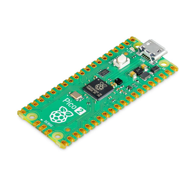
The Raspberry Pi Pico 2 is a new microcontroller board from the Raspberry Pi Foundation, based on the RP2350. It features a higher core clock speed, double the on-chip SRAM, double the on-board flash memory, more powerful Arm cores, optional RISC-V cores, new security features, and upgraded interfacing capabilities. The Raspberry Pi Pico 2 offers a significant boost in performance and features while maintaining hardware and software compatibility with earlier members of the Raspberry Pi Pico series.
The RP2350 provides a comprehensive security architecture built around Arm TrustZone for Cortex-M. It incorporates signed boot, 8 KB of antifuse OTP for key storage, SHA-256 acceleration, a hardware TRNG, and fast glitch detectors.
The unique dual-core, dual-architecture capability of the RP2350 allows users to choose between a pair of industry-standard Arm Cortex-M33 cores and a pair of open-hardware Hazard3 RISC-V cores. Programmable in C/C++ and Python, and supported by detailed documentation, the Raspberry Pi Pico 2 is the ideal microcontroller board for both enthusiasts and professional developers.
Specifications
CPU
Dual Arm Cortex-M33 or dual RISC-V Hazard3 processors @ 150 MHz
Memory
520 KB on-chip SRAM; 4 MB on-board QSPI flash
Interfaces
26 multi-purpose GPIO pins, including 4 that can be used for AD
Peripherals
2x UART
2x SPI controllers
2x I²C controllers
24x PWM channels
1x USB 1.1 controller and PHY, with host and device support
12x PIO state machines
Input power
1.8-5.5 V DC
Dimensions
21 x 51 mm
Downloads
Datasheet (Pico 2)
Datasheet (RP2350)
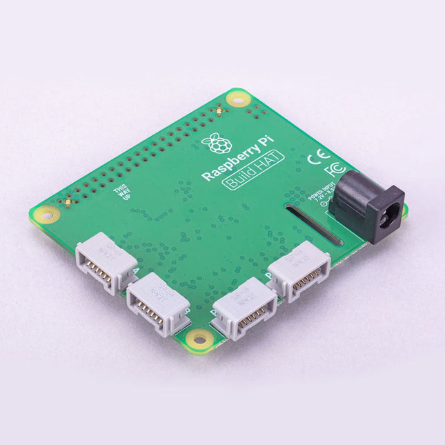
Build robust, intelligent machines that combine Raspberry Pi computing power with LEGO components.
The Raspberry Pi Build HAT provides four connectors for LEGO Technic motors and sensors from the SPIKE Portfolio. The available sensors include a distance sensor, a color sensor, and a versatile force sensor. The angular motors come in a range of sizes and include integrated encoders that can be queried to find their position.
The Build HAT fits all Raspberry Pi computers with a 40-pin GPIO header, including – with the addition of a ribbon cable or other extension device — Raspberry Pi 400. Connected LEGO Technic devices can easily be controlled in Python, alongside standard Raspberry Pi accessories such as a camera module.
Features
Controls up to 4 motors and sensors
Powers the Raspberry Pi (when used with a suitable external PSU)
Easy to use from Python on the Raspberry Pi
The SparkFun GPS-RTK2 raises the bar for high-precision GPS and is the latest in a line of powerful RTK boards featuring the ZED-F9P module from u-blox. The ZED-F9P is a top-of-the-line module for high accuracy GNSS and GPS location solutions, including RTK capable of 10 mm, three-dimensional accuracy. With this board, you will be able to know where your (or any object's) X, Y, and Z location is within roughly the width of your fingernail! The ZED-F9P is unique in that it is capable of both rover and base station operations. Utilizing our handy Qwiic system, no soldering is required to connect it to the rest of your system. However, we still have broken out 0.1"-spaced pins if you prefer to use a breadboard.
We've even included a rechargeable backup battery to keep the latest module configuration and satellite data available for up to two weeks. This battery helps 'warm-start' the module decreasing the time-to-first-fix dramatically. This module features a survey-in mode allowing the module to become a base station and produce RTCM 3.x correction data.
The number of configuration options of the ZED-F9P is incredible! Geofencing, variable I²C address, variable update rates, even the high precision RTK solution can be increased to 20 Hz. The GPS-RTK2 even has five communications ports which are all active simultaneously: USB-C (which enumerates as a COM port), UART1 (with 3.3 V TTL), UART2 for RTCM reception (with 3.3V TTL), I²C (via the two Qwiic connectors or broken out pins), and SPI.
Sparkfun has also written an extensive Arduino library for u-blox modules to easily read and control the GPS-RTK2 over the Qwiic Connect System. Leave NMEA behind! Start using a much lighter weight binary interface and give your microcontroller (and its one serial port) a break. The SparkFun Arduino library shows how to read latitude, longitude, even heading and speed over I²C without the need for constant serial polling.
Features
Concurrent reception of GPS, GLONASS, Galileo and BeiDou
Receives both L1C/A and L2C bands
Voltage: 5 V or 3.3 V, but all logic is 3.3 V
Current: 68 mA - 130 mA (varies with constellations and tracking state)
Time to First Fix: 25 s (cold), 2 s (hot)
Max Navigation Rate:
PVT (basic location over UBX binary protocol) - 25 Hz
RTK - 20 Hz
Raw - 25 Hz
Horizontal Position Accuracy:
2.5 m without RTK
0.010 m with RTK
Max Altitude: 50k m
Max Velocity: 500 m/s
2x Qwiic Connectors
Dimensions: 43.5 x 43.2 mm
Weight: 6.8 g
Raspberry Pi Pico W is a microcontroller board based on the Raspberry Pi RP2040 microcontroller chip.
The RP2040 microcontroller chip ('Raspberry Silicon') offers a dual-core ARM Cortex-M0+ processor (133 MHz), 256 KB RAM, 30 GPIO pins, and many other interface options. In addition, there is 2 MB of on-board QSPI flash memory for code and data storage.
Raspberry Pi Pico W has been designed to be a low cost yet flexible development platform for RP2040 with a 2.4 GHz wireless interface using an Infineon CYW43439. The wireless interface is connected via SPI to the RP2040.
Features of Pico W
RP2040 microcontroller with 2 MB of flash memory
On-board single-band 2.4 GHz wireless interfaces (802.11n)
Micro USB B port for power and data (and for reprogramming the flash)
40 pin 21 x 51 mm 'DIP' style 1 mm thick PCB with 0.1' through-hole pins also with edge castellations
Exposes 26 multi-function 3.3 V general purpose I/O (GPIO)
23 GPIO are digital-only, with three also being ADC capable
Can be surface mounted as a module
3-pin ARM serial wire debug (SWD) port
Simple yet highly flexible power supply architecture
Various options for easily powering the unit from micro USB, external supplies or batteries
High quality, low cost, high availability
Comprehensive SDK, software examples and documentation
Features of the RP2040 microcontroller
Dual-core cortex M0+ at up to 133 MHz
On-chip PLL allows variable core frequency
264 kByte multi-bank high performance SRAM
External Quad-SPI Flash with eXecute In Place (XIP) and 16 kByte on-chip cache
High performance full-crossbar bus fabric
On-board USB1.1 (device or host)
30 multi-function general purpose I/O (four can be used for ADC)
1.8-3.3 V I/O voltage
12-bit 500 ksps analogue to digital converter (ADC)
Various digital peripherals
2x UART, 2x I²C, 2x SPI, 16x PWM channels
1x timer with 4 alarms, 1x real time clock
2x programmable I/O (PIO) blocks, 8 state machines in total
Flexible, user-programmable high-speed I/O
Can emulate interfaces such as SD card and VGA
Note: Raspberry Pi Pico W I/O voltage is fixed at 3.3 V.
Downloads
Datasheet
Specifications of 3-pin Debug Connector
The Raspberry Pi Zero W extends the Raspberry Pi Zero family. The Raspberry Pi Zero W has all the functionality of the original Raspberry Pi Zero, but comes with added connectivity consisting of:
802.11 b/g/n wireless LAN
Bluetooth 4.1
Bluetooth Low Energy (BLE)
Other Features
1 GHz, single-core CPU
512 MB RAM
Mini HDMI and USB On-The-Go ports
Micro-USB power
HAT-compatible 40-pin header
Composite video and reset headers
CSI camera connector
Downloads
Mechanical Drawing
Schematics
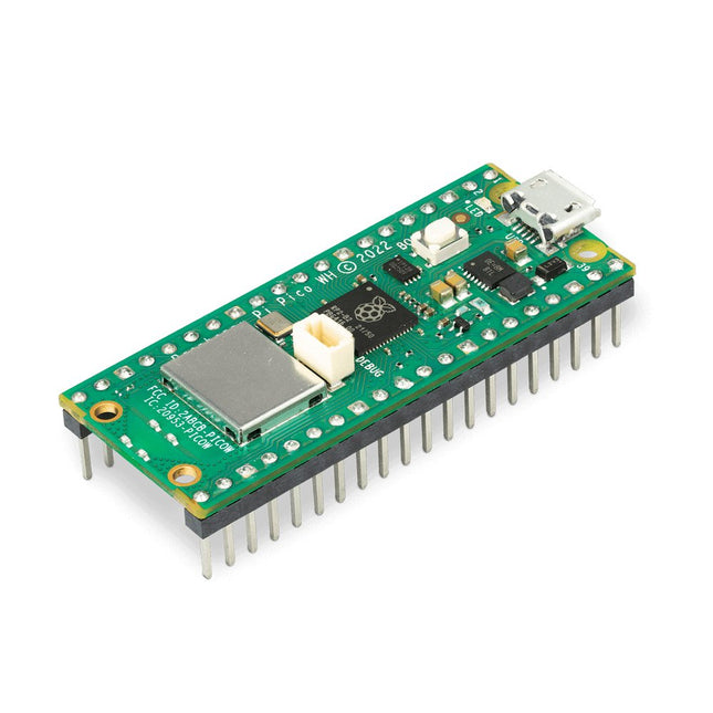
Raspberry Pi Pico WH is a microcontroller board based on the Raspberry Pi RP2040 microcontroller chip.
The RP2040 microcontroller chip ('Raspberry Silicon') offers a dual-core ARM Cortex-M0+ processor (133 MHz), 256 KB RAM, 30 GPIO pins, and many other interface options. In addition, there is 2 MB of on-board QSPI flash memory for code and data storage.
Raspberry Pi Pico WH has been designed to be a low cost yet flexible development platform for RP2040 with a 2.4 GHz wireless interface using an Infineon CYW43439. The wireless interface is connected via SPI to the RP2040.
Features of Pico WH
RP2040 microcontroller with 2 MB of flash memory
On-board single-band 2.4 GHz wireless interfaces (802.11n)
Micro USB B port for power and data (and for reprogramming the flash)
40 pin 21 x 51 mm 'DIP' style 1 mm thick PCB with 0.1' through-hole pins also with edge castellations
Exposes 26 multi-function 3.3 V general purpose I/O (GPIO)
23 GPIO are digital-only, with three also being ADC capable
Can be surface mounted as a module
3-pin ARM serial wire debug (SWD) port
Simple yet highly flexible power supply architecture
Various options for easily powering the unit from micro USB, external supplies or batteries
High quality, low cost, high availability
Comprehensive SDK, software examples and documentation
Pre-populated headers and 3-pin debug connector
Features of the RP2040 microcontroller
Dual-core cortex M0+ at up to 133 MHz
On-chip PLL allows variable core frequency
264 kByte multi-bank high performance SRAM
External Quad-SPI Flash with eXecute In Place (XIP) and 16 kByte on-chip cache
High performance full-crossbar bus fabric
On-board USB1.1 (device or host)
30 multi-function general purpose I/O (four can be used for ADC)
1.8-3.3 V I/O voltage
12-bit 500 ksps analogue to digital converter (ADC)
Various digital peripherals
2x UART, 2x I²C, 2x SPI, 16x PWM channels
1x timer with 4 alarms, 1x real time clock
2x programmable I/O (PIO) blocks, 8 state machines in total
Flexible, user-programmable high-speed I/O
Can emulate interfaces such as SD card and VGA
Note: Raspberry Pi Pico W I/O voltage is fixed at 3.3 V.
Downloads
Datasheet
Specifications of 3-pin Debug Connector
The Raspberry Pi Monitor is a 15.6-inch Full HD computer display. User-friendly, versatile, compact and affordable, it is the perfect desktop display companion for both Raspberry Pi computers and other devices.
With built-in audio via two front-facing speakers, and VESA and screw mounting options as well as an integrated angle-adjustable stand, the Raspberry Pi Monitor is ideal for desktop use or for integration into projects and systems. It can be powered directly from a Raspberry Pi, or by a separate power supply.
Features
15.6-inch full HD 1080p IPS display
Integrated angle-adjustable stand
Built-in audio via two front-facing speakers
Audio out via 3.5 mm jack
Full-size HDMI input
VESA and screw mounting options
Volume and brightness control buttons
USB-C power cable
Specifications
Display
Screen size: 15.6 inches, 16:9 ratio
Panel type: IPS LCD with anti-glare coating
Display resolution: 1920 x 1080
Color depth: 16.2M
Brightness (typical): 250 nits
Color gamut: 45%
Viewing angle: 80°
Power
1.5 A/5 V
Can be powered directly from a Raspberry Pi USB port (max 60% brightness, 50% volume) or by a separate power supply (max 100% brightness, 100% volume)
Connectivity
Standard HDMI port (1.4 compliant)
3.5 mm stereo headphone jack
USB-C (power in)
Audio
2x 1.2 W integrated speakers
Support for 44.1 kHz, 48 kHz, and 96 kHz sample rates
Downloads
Datasheet