Clearance Sale %
-
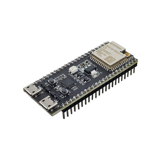
Espressif ESP32-S3-DevKitC-1U-N8R8
The ESP32-S3-DevKitC-1 is an entry-level development board equipped with ESP32-S3-WROOM-1U, a general-purpose Wi-Fi + Bluetooth Low Energy MCU module that integrates complete Wi-Fi and Bluetooth Low Energy functions. Most of the I/O pins on the module are broken out to the pin headers on both sides of this board for easy interfacing. Developers can either connect peripherals with jumper wires or mount ESP32-S3-DevKitC-1 on a breadboard. Features Module integrated: ESP32-S3-WROOM-1U-N8R8 Flash: 8 MB QD PSRAM: 8 MB OT SPI voltage: 3.3 V Specifications ESP32-S3-WROOM-1U ESP32-S3-WROOM-1U is a powerful, generic Wi-Fi + Bluetooth Low Energy MCU module that has a rich set of peripherals. It provides acceleration for neural network computing and signal processing workloads. ESP32-S3-WROOM-1U comes with an external antenna connector. 5 V to 3.3 V LDO Power regulator that converts a 5 V supply into a 3.3 V output. Pin Headers All available GPIO pins (except for the SPI bus for flash) are broken out to the pin headers on the board for easy interfacing and programming. USB-to-UART Port A Micro-USB port used for power supply to the board, for flashing applications to the chip, as well as for communication with the chip via the on-board USB-to-UART bridge. Boot Button Download button. Holding down Boot and then pressing Reset initiates Firmware Download mode for downloading firmware through the serial port. Reset Button Press this button to restart the system. USB Port ESP32-S3 full-speed USB OTG interface, compliant with the USB 1.1 specification. The interface is used for power supply to the board, for flashing applications to the chip, for communication with the chip using USB 1.1 protocols, as well as for JTAG debugging. USB-to-UART Bridge Single USB-to-UART bridge chip provides transfer rates up to 3 Mbps. RGB LED Addressable RGB LED, driven by GPIO38. 3.3 V Power On LED Turns on when the USB power is connected to the board. Downloads Pinout
€ 29,95€ 14,95
Members identical
-

FTDI FTDI Serial TTL RS232 USB Cable
This FTDI USB to TTL (3.3 V I/O) Serial Cable (FTDI TTL-232R-3V3 OEM) is a professional, high quality, high speed device which allows a simple and easy way to connect TTL interface devices using a spare USB port. Features TTL-232R-3V3 FTDI USB to TTL 3.3 V Serial Cable FTDI TTL-232R-3V3 Cable 6 Way The FTDI USB to TTL 3.3 V features a FTDI FT232R device integrated within the cable FTDI USB to TTL Serial 3.3 V Adapter Cable 6 Pin 0.1' Female Socket Header UART IC FT232RL Chip Compatible with Windows 7/8/10 and Linux
€ 19,95€ 9,95
Members identical
-

Zhongdi Desoldering Tip Set for ZD Models
This set contains 3 desoldering tips for digital desoldering stations such as ZD-915 or ZD-8965. Included 1x Desoldering tip N5-1 (0.8 mm) 1x Desoldering tip N5-2 (1.0 mm) 1x Desoldering tip N5-3 (1.3 mm)
€ 9,95€ 4,95
Members identical
-

Pimoroni Pimoroni Raspberry Pi Pico VGA Demo Base
Based on the reference design by Raspberry Pi, our Pimoroni Pico VGA Demo Base is a great way to start experimenting with Raspberry Pi Pico/RP2040. It's the perfect way to demo of some of the fun things you can achieve with the RP2040 microcontroller such as generating a solid VGA output without taxing the CPU at all! Amaze your friends by showing them you still own a D-sub cable! Bask in the glory of 15-bit analog video! Get teary eyed over the warm, authentic, RC filtered PWM audio! This board will run the various video example programs that Raspberry Pi have put together to demonstrate features of the RP2040. Features 15-pin VGA (D-sub) connector PCM5100A DAC for line out audio over I²S (datasheet) PWM audio output SD card slot Reset button Female headers to install your Raspberry Pi Pico Three user-controllable switches Rubber feet Compatible with Raspberry Pi Pico No soldering required (as long as your Pico has header pins attached) Programmable with C/C++
€ 29,95€ 14,95
Members identical
-
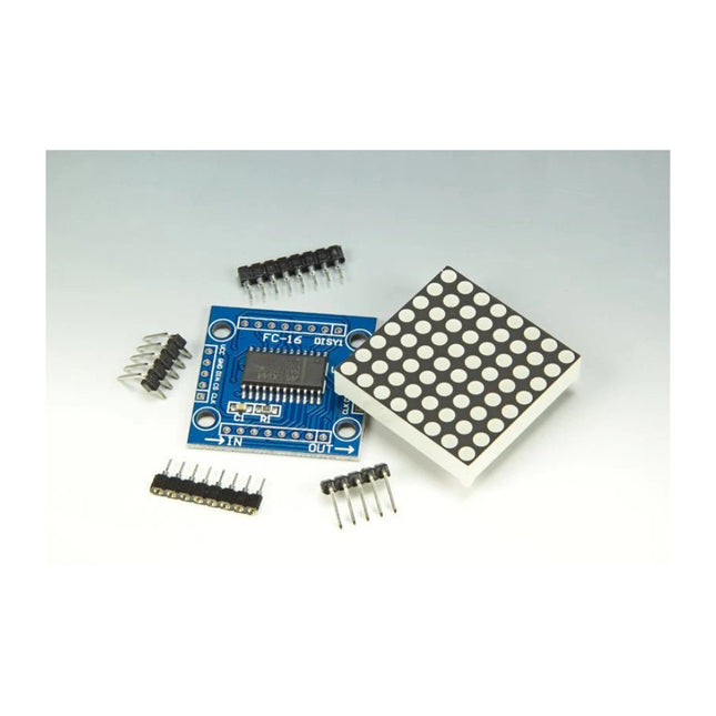
Elektor Labs MAX7219 Dot Matrix Module (Set of 8)
Scrolling text display with eight 8 x 8 LED dot matrix displays (512 LEDs in total). Built around an ESP-12F Wi-Fi module (ESP8266-based) programmed in the Arduino IDE. ESP8266 web server allows control of displayed text, scroll delay and brightness with a mobile phone or other Wi-Fi-connected (portable) device. Features 10 MHz Serial Interface Individual LED Segment Control Decode/No-Decode Digit Selection 150 µA Low-Power Shutdown (Data Retained) Digital and Analog Brightness Control Display Blanked on Power-Up Drive Common-Cathode LED Display Slew-Rate Limited Segment Drivers for Lower EMI (MAX7221) SPI, QSPI, MICROWIRE Serial Interface (MAX7221) 24-Pin DIP and SO Packages
€ 19,95€ 9,95
Members identical
-
JOY-iT Case for 7" RGB-Touch-Display for Raspberry Pi
Case for 7' RGB-Touch-Display for Raspberry Pi
€ 12,95€ 6,50
Members identical
-
Raspberry Pi Foundation Official Raspberry Pi 4 Desktop Kit (EU)
This 'All in One' Raspberry Pi 4 Desktop Starterkit contains all official parts and allows an easy and quick start! Raspberry Pi 4 Desktop Kit contains: Raspberry Pi US Keyboard & Mouse 2x micro HDMI to Standard HDMI cable (A/M) 1 m Raspberry Pi 15.3 W USB-C Power Supply (EU version) Raspberry Pi 4 Case Official Raspberry Pi Beginner's Guide (English language) 16 GB NOOBS with Raspbian microSD card Raspberry Pi 4 B is NOT included.
€ 64,95€ 32,50
Members identical
-

Raspberry Pi Foundation Official Raspberry Pi US Keyboard (white/red)
The official Raspberry Pi keyboard and hub is a standard 78-key US keyboard that includes an additional three USB 2.0 type A ports to power other peripherals. The keyboard is available in different language/country options as detailed below. 78-key US keyboard Three USB 2.0 type A ports for powering other peripherals Automatic keyboard language detection USB type A to micro USB type B cable included for connection to compatible computer Ergonomic design for comfortable use Compatible with all Raspberry Pi products
€ 17,95€ 8,95
Members identical
-
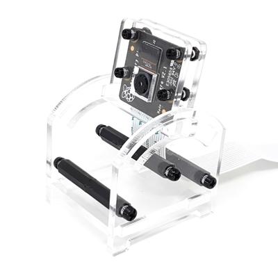
Generic Adjustable Raspberry Pi Camera Mount & Protector
Features Simple slide angle adjustment Camera Module protection 'sandwich' plates Made from crystal clear laser-cut acrylic in the UK 1/4 inch hole for tripod mounting Stable 4-leg base Here you can find the Assembly Instructions.
€ 9,95€ 4,95
Members identical
-
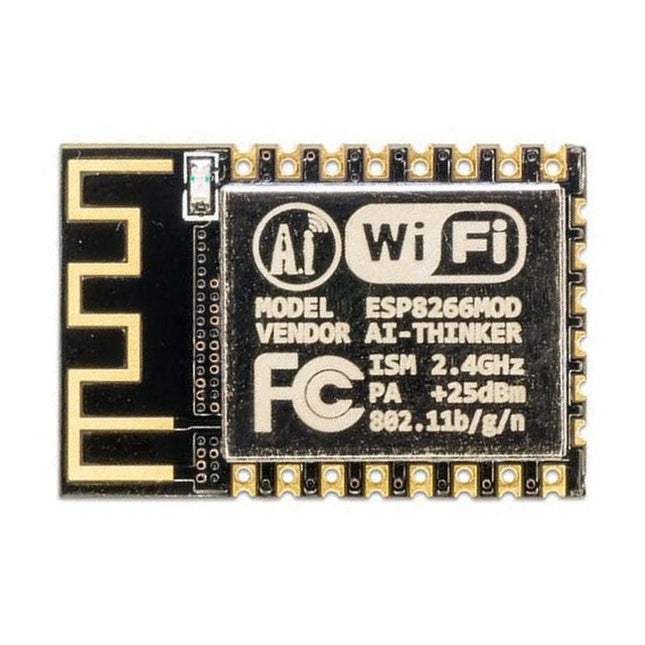
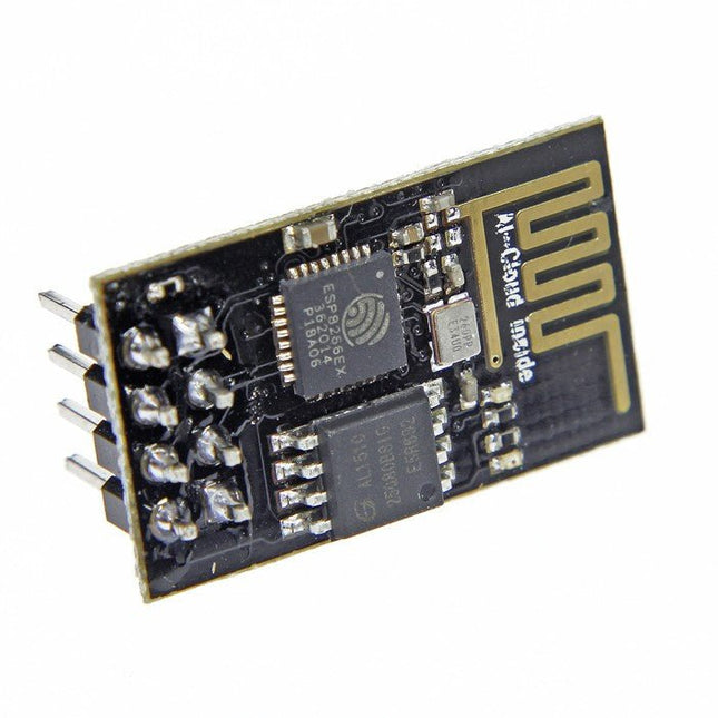
Espressif ESP-12F - ESP8266-based Wi-Fi Module
This Wi-Fi module is based on the popular ESP8266 chip. The module is FCC and CE certified and RoHS compliant. Fully compatible with ESP-12E. 13 GPIO pins, 1 analog input, 4 MB flash memory.
€ 8,95€ 4,50
Members identical
-
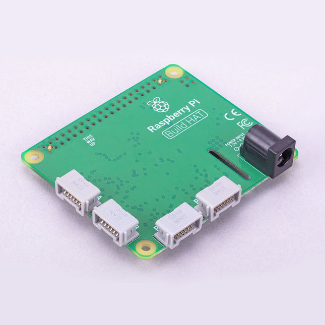
Raspberry Pi Foundation Raspberry Pi Build HAT
Build robust, intelligent machines that combine Raspberry Pi computing power with LEGO components. The Raspberry Pi Build HAT provides four connectors for LEGO Technic motors and sensors from the SPIKE Portfolio. The available sensors include a distance sensor, a color sensor, and a versatile force sensor. The angular motors come in a range of sizes and include integrated encoders that can be queried to find their position. The Build HAT fits all Raspberry Pi computers with a 40-pin GPIO header, including – with the addition of a ribbon cable or other extension device — Raspberry Pi 400. Connected LEGO Technic devices can easily be controlled in Python, alongside standard Raspberry Pi accessories such as a camera module. Features Controls up to 4 motors and sensors Powers the Raspberry Pi (when used with a suitable external PSU) Easy to use from Python on the Raspberry Pi
€ 29,95€ 14,95
Members identical
-

JOY-iT Passive Cooling for Raspberry Pi (Heatsink)
Aluminium Heatsink Set for Raspberry Pi with pre-applied tape for easy installation 1 piece: 14 x 15 x 5 mm 2 pieces: 8 x 8 x 5 mm
€ 3,95€ 1,95
Members identical
-
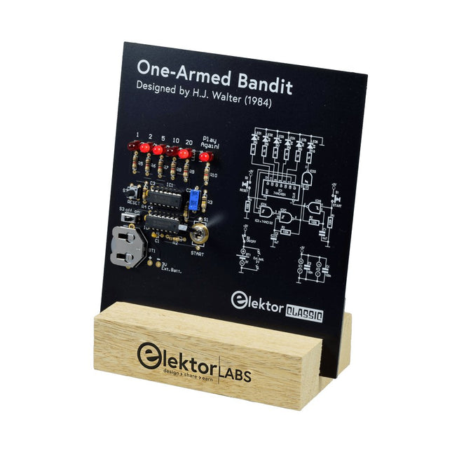
Elektor Labs Elektor One-armed Bandit
Pull Down Lever For Highest Score! This Elektor Circuit Classic from 1984 shows a playful application of CMOS 400x series logic ICs in combination with LEDs, a highly popular combination at the time. The project imitates a spinning-digit type slot machine. The Game To play the game, first agree on the number of rounds. Player 1 actuates the switch lever as long as desired and releases it. The LEDs then show the score which is the sum of the 50-20-10-5 digits lit up. If the Play Again! LED lights, Player 1 has another, “free” round. If not, it’s Player 2’s turn. The players keep tab of their scores, and the highest score wins. Features LEDs Indicate Score Multi-Player and Play Again! Elektor Heritage Circuit Symbols Tried & Tested by Elektor Labs Educational & Geeky Project Through-Hole Parts Only Included Printed Circuit Board All Components Wooden Stand Bill of Materials Resistors (5%, 250 mW) R1,R2,R3,R4 = 100kΩ R5,R6,R7,R8,R9,R10 = 1kΩ Capacitors C1 = 4.7nF, 10%, 50V, 5mm C2 = 4.7μF, 10%, 63V, axial C3,C4 = 100nF, 10 %, 50V, ceramic X7R, 5mm Semiconductors LED1-LED6 = red, 5mm (T1 3/4) IC1 = 74HC4024 IC2 = 74HC132 Miscellaneous S1 = switch, toggle, 21mm lever, SPDT, momentary S2 = switch, tactile, 24V, 50mA, 6x6mm S3 = switch, slide, SPDT IC1,IC2 = IC socket, DIP14 BT1 = PCB-mount CR2032 battery retainer clip Desktop Stand PCB 230098-1 Not included: BT1 = CR2032 coin cell battery
€ 39,95€ 19,95
Members identical
-
Espressif ESP8266 ESP-01 WiFi Module
The ESP8266 is an impressive, low cost WiFi module suitable for adding WiFi functionality to an existing microcontroller project via a UART serial connection. The module can even be reprogrammed to act as a standalone WiFi connected device – just add power! 802.11 b/g/n protocol Wi-Fi Direct (P2P), soft-AP Integrated TCP/IP protocol stack This module is a self-contained SOC (System On a Chip) that doesn’t necessarily need a microcontroller to manipulate inputs and outputs as you would normally do with an Arduino , for example, because the ESP-01 acts as a small computer. Thus, you can give a microcontroller internet access like the Wi-Fi shield does to the Arduino, or you can simply program the ESP8266 to not only have access to a Wi-Fi network, but to act as a microcontroller as well, which makes the ESP8266 very versatile.
€ 7,50€ 3,75
Members identical
-
Raspberry Pi Foundation Bumper for Raspberry Pi 5
The Raspberry Pi Bumper is a snap-on silicone cover that protects the bottom and edges of the Raspberry Pi 5. Features One-piece flexible silicone rubber bumper Enables easy access to the power button Mounting holes remain accessible underneath the bumper Downloads Datasheet
€ 3,50€ 1,75
Members identical
-
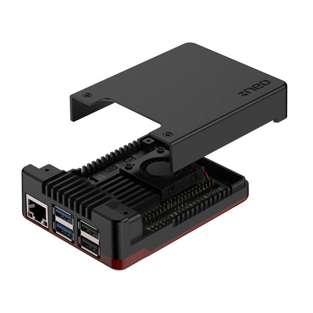
Argon Argon NEO 5 BRED Case for Raspberry Pi 5
The Argon NEO 5 is redesigned specifically to meet the high demands of the Raspberry Pi 5. It offers an impressive heat dissipation solution for both passive and active cooling. Aluminum case enclosure with passive cooling fins that act as the heatsink Air intake vents allow for cool air to enter the case 30 mm PWM fan helps with the airflow and push out hot air to exhaust vents Simple and beautifully designed Made with aluminum alloy and polished with a Black & Red finish for stunning aesthetics. Easy assembly for the 3 part case with the Raspberry Pi 5. Small foot print allows to bring it anywhere – or easily mount to your desired station with built in mounting points. Complete access to all ports with the removable top cover. Superior protection & security Space grade aluminum helps protect Raspberry Pi 5 board from physical damage. The case has a screw on top cover to keep the ports safe when not in use. Optional SD card cover to protect your data even further. Native Raspberry Pi 5 board support Integrated power button LED light display
€ 24,95€ 12,50
Members identical
-
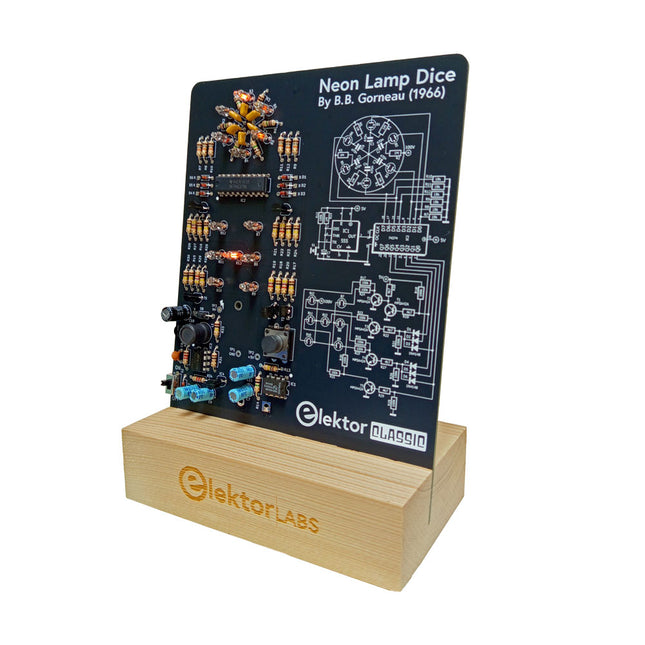
Elektor Labs Elektor Neon Lamp Dice
A Retro Roll with a Neon Soul LED-based dice are common, but their light is cold. Not so for this electronic neon dice, which displays its value with the warm glow of neon lamps. It is perfect for playing games on cold, dark winter evenings. The pips of the dice are neon lamps and the random number generator has six neon lamps to show that it is working. Even though the dice has an on-board 100-V power supply, it is completely safe. As with all Elektor Classic products, the dice too has its circuit diagram printed on the front while an explanation of how the circuit works can be found on the rear side. The Neon Lamp Dice comes as a kit of easy-to-solder through-hole parts. The power supply is a 9-V battery (not included). Features Warm Vintage Glow Elektor Heritage Circuit Symbols Tried & Tested by Elektor Labs Educational & Geeky Project Through-Hole Parts Only Included Printed Circuit Board All Components Wooden Stand Required 9 V battery Component List Resistors (THT, 150 V, 0.25 W) R1, R2, R3, R4, R5, R6, R14 = 1 MΩ R7, R8, R9, R10, R11, R12 = 18 kΩ R13, R15, R16, R17, R18, R21, R23, R24, R25, R26, R28, R30, R33 = 100 kΩ R32, R34 = 1.2 kΩ R19, R20, R22, R27, R29 = 4.7 kΩ R31 = 1 Ω Capacitors C1, C2, C3, C4, C5, C6 = 470 nF, 50 V, 5 mm pitch C7, C9, C11, C12 = 1 µF, 16 V, 2 mm pitch C8 = 470 pF, 50 V, 5 mm pitch C10 = 1 µF, 250 V, 2.5 mm pitch Inductors L1 = 470 µH Semiconductors D1, D2, D3, D4, D5, D6, D7 = 1N4148 D8 = STPS1150 IC1 = NE555 IC2 = 74HC374 IC3 = MC34063 IC4 = 78L05 T1, T2, T3, T4, T5 = MPSA42 T6 = STQ2LN60K3-AP Miscellaneous K1 = PP3 9 V battery holder NE1, NE2, NE3, NE4, NE5, NE6, NE7, NE8, NE9, NE10, NE11, NE12, NE13 = neon light S2 = Miniature slide switch S1 = Pushbutton (12 x 12 mm)
€ 39,95€ 19,95
Members identical
-
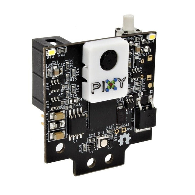
Charmed Labs Pixy2 CMUcam5 – Smart Vision Sensor
Pixy2 can be taught to detect objects by the press of a button. It is equipped with a new line detection algorithm to use on line-following robots. It can learn to recognize intersection and follow road signs. Pixy2 comes with various cables so that you can connect it with an Arduino or a Raspberry Pi out of the box. Furthermore, the I/O port offers several interfaces (SOI, I²C, UART, USB) to plug your Pixy2 in most boards. Downloads Documentation Projects Software
€ 94,95€ 47,50
Members identical
-

Generic Plasma Magic Ball (6 inch)
Create lightning with the touch of your fingers or the clap of your hands The Plasma Magic Ball is a cutting-edge tech gadget and an eye-catching piece of art. Inside the glass sphere, a special gas mixture creates mesmerizing light effects when activated by high-frequency current – like holding a storm in your hands. Perfect for use at home, in the office, schools, hotels, or bars, it’s a unique decorative element that sparks curiosity. Looking for a fun and unusual gift? The Plasma Magic Ball is a great choice for friends and family alike. Despite its stunning effects, the Plasma Magic Ball uses very little electricity. The glass itself is made of specially hardened, high-strength material and can withstand temperatures of up to 522°C (972°F). Specifications Material Plastic Ball diameter 6 inch (15 cm) Input voltage 220 V Output voltage 12 V Power 15 W Dimensions 25 x 15.5 x 15.5 cm
€ 29,95€ 14,95
Members identical
-
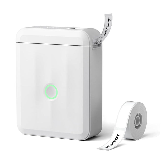
Niimbot Niimbot D110 Label Printer
Based on direct thermal technology, the Niimbot D110 label printer offers a printing experience without ink, toner or ribbons, making it a cost-effective solution compared to traditional printers. Its compact size and light weight make it easy to transport and fits easily into any pocket. With Bluetooth connectivity and a built-in 1500 mAh battery, this wireless mini printer allows you to print from up to 10 meters away, giving you flexibility on the go, whether you're printing from your smartphone or tablet. The "Niimbot" app (available for iOS and Android) offers a variety of free templates for customizing labels. Specifications Model D110_M (Upgraded Version 2024) Material ABS Resolution 203 DPI Printing speed 30-60 mm/s Print width 12-15 mm Printing technology Thermal Operating temperature 5°C ~ 45°C (41°F ~ 113°F) Battery capacity 1500 mAh Charging interface USB-C Charging time 2 hours Connection Bluetooth 4.0 Wireless distance 10 m Dimensions 98 x 76 x 30 mm Weight 149 g Included 1x Niimbot D110 Label Printer 1x Label tape (12 x 40 mm) 1x USB cable 1x Manual Downloads iOS App Android App
€ 29,95€ 19,95
Members identical
-
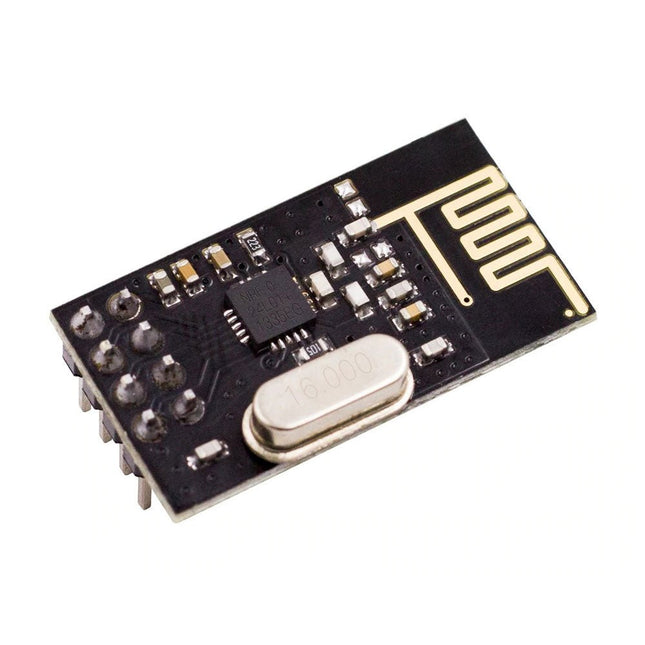
Kuongshun nRF24L01+ Wireless Transceiver Module (2.4 GHz)
NRF24L01 is a universal ISM band monolithic transceiver chip works in the 2.4-2.5 GHz. Features Wireless transceiver including: Frequency generator, enhanced type, SchockBurstTM, mode controller, power amplifier, crystal amplifier, modulator, demodulator The output power channel selection and protocol settings can be set extremely low current consumption, through the SPI interface As the transmit mode, the transmit power is 6 dBm, the current is 9.0 mA, the accepted mode current is 12.3 mA, the current consumption of the power-down mode and standby mode are lower Built-in 2.4 GHz antenna, supports up to six channels of data reception Size: 15 x 29 mm (including antenna)
€ 7,95€ 3,95
Members identical
-
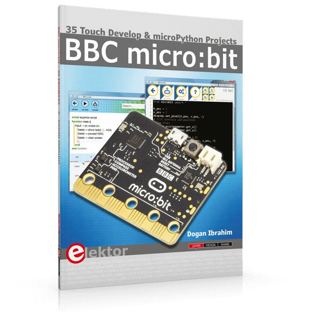
Elektor Publishing BBC micro:bit (Book)
35 Touch Develop & MicroPython Projects The BBC micro:bit is a credit sized computer based on a highly popular and high performance ARM processor. The device is designed by a group of 29 partners for use in computer education in the UK and will be given free of charge to every secondary school student in the UK. The device is based on the Cortex-M0 processor and it measures 4 x 5 cm. It includes several important sensors and modules such as an accelerometer, magnetometer, 25 LEDs, 2 programmable push-button switches, Bluetooth connectivity, micro USB socket, 5 ring type connectors, and a 23-pin edge connector. The device can be powered from its micro USB port by connecting it to a PC, or two external AAA type batteries can be used. This book is about the use of the BBC micro:bit computer in practical projects. The BBC micro:bit computer can be programmed using several different programming languages, such as Microsoft Block Editor, Microsoft Touch Develop, MicroPython, and JavaScript. The book makes a brief introduction to the Touch Develop programming language and the MicroPython programming language. It then gives 35 example working and tested projects using these language. Readers who learn to program in Touch Develop and MicroPython should find it very easy to program using the Block Editor or any other languages. The following are given for each project: Title of the project Description of the project Aim of the project Touch Develop and MicroPython program listings Complete program listings are given for each project. In addition, working principles of the projects are described briefly in each section. Readers are encouraged to go through the projects in the order given in the book.
€ 29,95€ 14,95
Members identical
-

Zhongdi Hot Glue Sticks (100 mm, 12 pcs)
These 10 cm long hot glue sticks are compatible with all standard hot glue guns with a diameter of 7.2 mm.
€ 2,95€ 1,50
Members identical
-
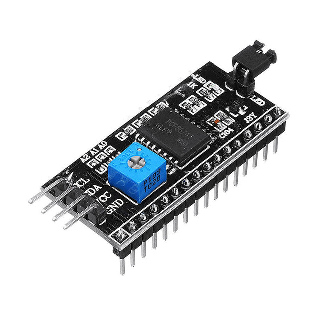
Kuongshun IIC/I²C Serial Interface Adapter Module
This is another great IIC/I²C/TWI/SPI Serial Interface. As the pin resources of controller is limited, your project may be not able to use normal LCD shield after connected with a certain quantity of sensors or SD card. However, with this I²C interface module, you will be able to realize data display via only 2 wires. If you already has I²C devices in your project, this LCD module actually cost no more resources at all. It is fantastic for based project. I²C Address: 0X20~0X27 (the original address is 0X20,you can change it yourself) The backlight and contrast is adjusted by potentiometer Comes with 2 IIC interface, which can be connected by Dupont Line or IIC dedicated cable I²C Address: 0x27 (I²C Address: 0X20~0X27 (the original address is 0X27,you can change it yourself) Specifications Compatible for 1602 LCD Supply voltage: 5 V Weight: 5 g Size: 5.5 x 2.3 x 1.4 cm
€ 4,95€ 2,50
Members identical


