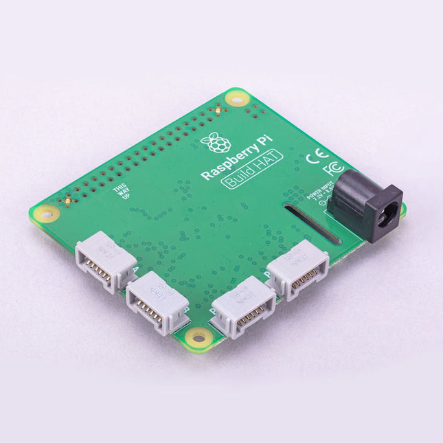
Build robust, intelligent machines that combine Raspberry Pi computing power with LEGO components.
The Raspberry Pi Build HAT provides four connectors for LEGO Technic motors and sensors from the SPIKE Portfolio. The available sensors include a distance sensor, a color sensor, and a versatile force sensor. The angular motors come in a range of sizes and include integrated encoders that can be queried to find their position.
The Build HAT fits all Raspberry Pi computers with a 40-pin GPIO header, including – with the addition of a ribbon cable or other extension device — Raspberry Pi 400. Connected LEGO Technic devices can easily be controlled in Python, alongside standard Raspberry Pi accessories such as a camera module.
Features
Controls up to 4 motors and sensors
Powers the Raspberry Pi (when used with a suitable external PSU)
Easy to use from Python on the Raspberry Pi
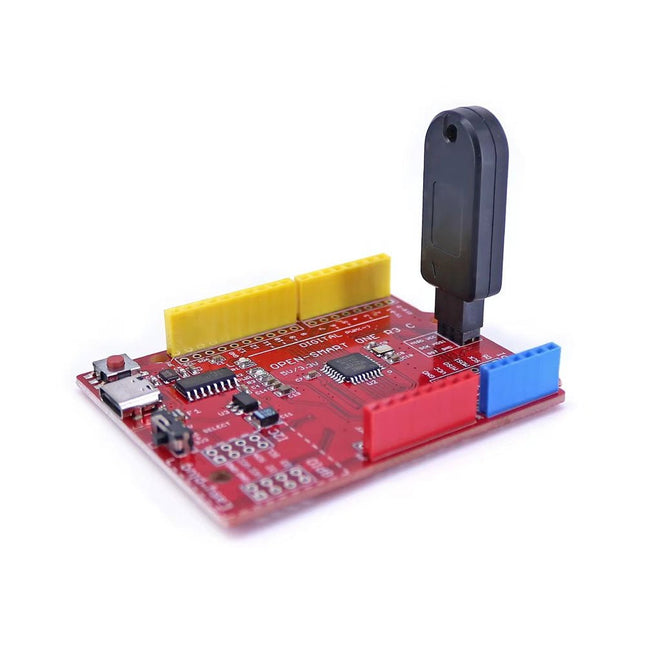
This programmer is specifically designed for burning bootloaders (without a computer) on Arduino-compatible ATmega328P/ATmega328PB development boards.
Simply plug the programmer into the ICSP interface to re-burn the bootloader. It’s also compatible with new chips, provided the IC is functional.
Note: Burning a bootloader erases all previous chip data.
Features
Working voltage: 3.1-5.3 V
Working current: 10 mA
Compatible with Arduino Uno R3 based boards (ATmega328P or ATmega328PB)
Dimensions: 39.6 x 15.5 x 7.8 mm
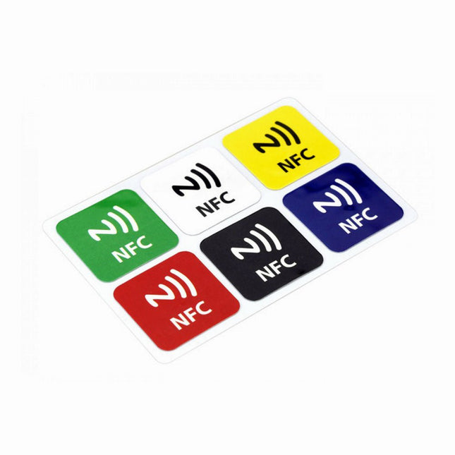
Features NFC chip material: PET + Etching antenna Chip: NTAG216 (compatible with all NFC phones) Frequency: 13.56 MHz (High Frequency) Reading time: 1 - 2 ms Storage capacity: 888 bytes Read and write times: > 100,000 times Reading distance: 0 - 5 mm Data retention: > 10 years NFC chip size: Diameter 30 mm Non-contact, no friction, the failure rate is small, low maintenance costs Read rate, verification speed, which can effectively save time and improve efficiency Waterproof, dustproof, anti-vibration No power comes with an antenna, embedded encryption control logic, and communication logic circuit Included 1x NFC Stickers (6-color kit)
Specifications
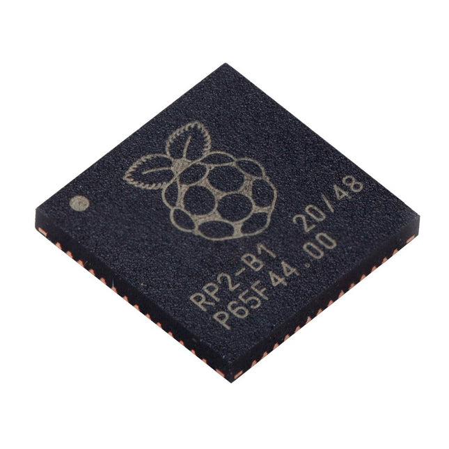
Dual ARM Cortex-M0+ @ 133 MHz
264 kB on-chip SRAM in six independent banks
Support for up to 16 MB of off-chip Flash memory via dedicated QSPI bus
DMA controller
Fully-connected AHB crossbar
Interpolator and integer divider peripherals
On-chip programmable LDO to generate core voltage
2x on-chip PLLs to generate USB and core clocks
30x GPIO pins, 4 of which can be used as analogue inputs
Peripherals
2x UARTs
2x SPI controllers
2x I²C controllers
16x PWM channels
USB 1.1 controller and PHY, with host and device support
8x PIO state machines
What you'll get
10x bare RP2040 chips
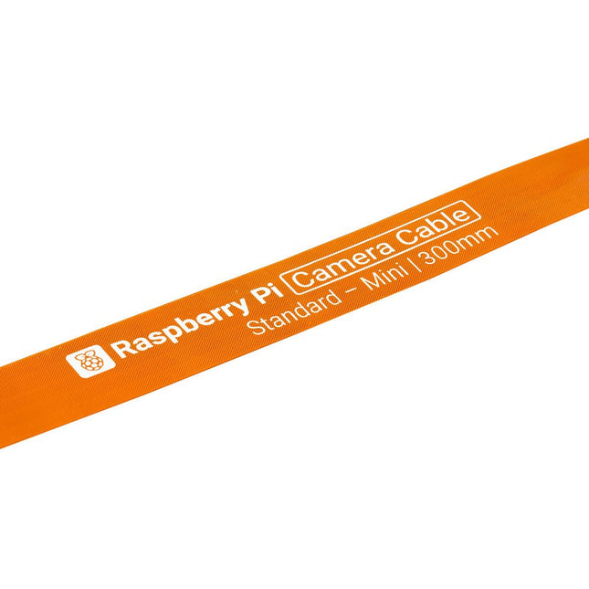
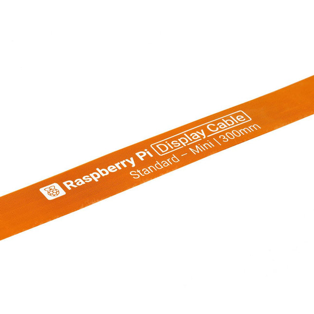
Raspberry Pi 5 provides two four-lane MIPI connectors, each of which can support either a camera or a display. These connectors use the same 22-way, 0.5 mm-pitch “mini” FPC format as the Compute Module Development Kit, and require adapter cables to connect to the 15-way, 1 mm-pitch “standard” format connectors on current Raspbery Pi camera and display products.These mini-to-standard adapter cables for cameras and displays (note that a camera cable should not be used with a display, and vice versa) are available in 200 mm, 300 mm and 500 mm lengths.
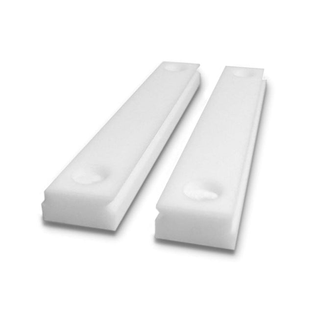
An upgraded jaw set that withstands direct contact with a soldering iron
Stickvise High Temperature PTFE Vise Jaws will withstand accidental contact with a soldering iron and will not melt. These are a great upgrade for your Stickvise.
Features
Made from PTFE with extremely high melting point
Withstands incidental contact with a soldering iron
This is the jaw plates only, does not include a Stickvise
Specifications
Material
Aluminum
Dimensions
73 x 53 x 3 mm
Weight
21 g
Raspberry Pi 5 provides two four-lane MIPI connectors, each of which can support either a camera or a display. These connectors use the same 22-way, 0.5 mm-pitch “mini” FPC format as the Compute Module Development Kit, and require adapter cables to connect to the 15-way, 1 mm-pitch “standard” format connectors on current Raspbery Pi camera and display products.These mini-to-standard adapter cables for cameras and displays (note that a camera cable should not be used with a display, and vice versa) are available in 200 mm, 300 mm and 500 mm lengths.
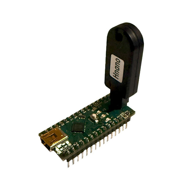
This programmer is specifically designed for burning bootloaders (without a computer) on Arduino-compatible ATmega328 development boards.
Simply plug the programmer into the ICSP interface to re-burn the bootloader. It’s also compatible with new chips, provided the IC is functional.
Note: Burning a bootloader erases all previous chip data.
Features
Working voltage: 3.1-5.3 V
Working current: 10 mA
Compatible with Arduino Nano based boards (ATmega328)
Dimensions: 39.6 x 15.5 x 7.8 mm
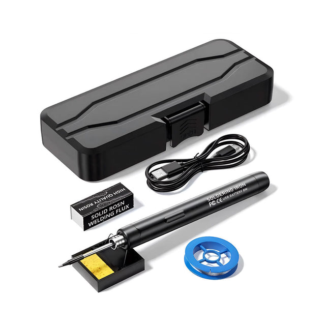
The Smart USB Soldering Iron Kit is a compact, cordless solution designed for precision and portability. Featuring intelligent three-speed temperature control (300-450°C) with an easy-to-read LED display, it heats up in just 10 seconds and melts solder in as little as 6 seconds.
The 1000 mAh rechargeable battery delivers up to 30 minutes of continuous use, making it ideal for quick repairs, electronics projects, and DIY tasks. With a plug-and-play, replaceable tip and a high-temperature-resistant insulated shell, it’s safe, user-friendly, and perfect for both beginners and professionals on the go.
Features
Three-Speed Intelligent Temperature Adjustment: Features an LED display screen with adjustable temperatures between 300-450°C (572-842°F). Easily switch between Celsius and Fahrenheit.
Integrated Plug-In Soldering Iron Tip: Plug-and-play design. The tip can be replaced by simply unscrewing it, ensuring quick and convenient operation.
Safe and Durable Design: High-temperature-resistant, insulated shell for enhanced safety during use.
Battery Capacity: Equipped with a rechargeable 1000 mAh battery that supports up to 30 minutes of continuous operation on a full charge – ideal for everyday tasks.
Efficient Performance: 8 W power with an integrated heating core for rapid heat-up. Melts tin in just 6 seconds, providing excellent thermal conductivity.
Easy to Use: After powering on via USB, set your desired temperature. The soldering iron heats up in 10 seconds. Once finished, place the tip on the stand—it cools down within 1 minute. Perfect for beginners, hobbyists, basic home repairs, and training engineers.
Cordless Innovation: This cordless soldering kit includes a built-in rechargeable lithium-ion battery, eliminating the need for cables. Versatile use for circuit board soldering, electrical repairs, jewelry making, metal crafts, computer maintenance, and DIY projects.
Specifications
Adjustable Temperature: 300-450°C (572-842°F)
Tin Melting Time: <15 seconds
Working Voltage: 5 V
Power Output: 8 W
Battery Capacity: 1000 mAh
Auto Sleep Function: Activates after 10 minutes of inactivity
Charging Time: Approx. 90 minutes
Battery Life: Up to 30 minutes continuous use
Charging Interface: USB-C
Main Material: Aluminum alloy
Dimensions: 190 x 16 mm (7.4 x 0.6")
Included
1x USB Soldering Iron
1x Soldering Tip
1x Soldering Rosin
1x Soldering Iron Holder (with Sponge)
1x USB-C Charging Cable
1x Solder Wire
1x Storage Box
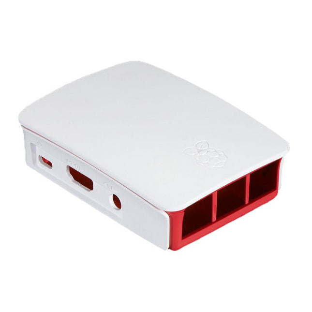
High-quality ABS construction
Removable side panels and lid for easy access to GPIO, camera and display connectors
Light pipes for power and activity LEDs
Extraordinarily handsome
Colour: white/red
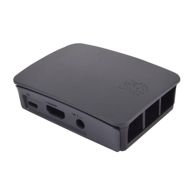
High-quality ABS construction
Removable side panels and lid for easy access to GPIO, camera and display connectors
Light pipes for power and activity LEDs
Extraordinarily handsome
Colour: black/grey
Features
Build in USB to Serial interface
Build-in PCB antenna
Powered by Pineseed BL602 SoC using Pinenut model: 12S stamp
2 MB Flash
USB-C connection
Suitable to breadboard BIY project
On board three color LEDs output
Dimensions: 25.4 x 44.0 mm
Note: USB cable is not included.
The JOY-iT Armor Case BLOCK is a robust aluminum enclosure designed specifically for the Raspberry Pi 5. It offers excellent protection against heat and physical shocks, making it suitable for challenging environments. Its compact design ensures that it doesn't require additional space, allowing for seamless integration into existing projects.
The case includes a large heatsink to enhance cooling efficiency. Installation is straightforward, with four screws (included) securing the case to the Raspberry Pi.
Specifications
Material
CNC milled aluminum alloy
Cooling performance
Idle: ~39°CFull load: ~75°C
Special features
Large heat sink, protection against shocks and heat with the same volume as without housing
Dimensions (top side)
69 x 56 x 15,5 mm
Dimensions (bottom side)
87 x 56 x 7,5 mm
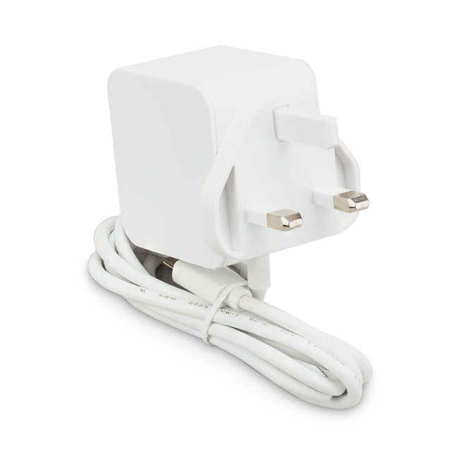
The Raspberry Pi 27 W PD USB-C power supply is designed specifically to power the Raspberry Pi 5. It is also capable of delivering 5 V/3 A, 9 V/3 A, 12 V/2.25 A, 15 V/1.8 A to PD-compatible products, making it a good and cost-effective power supply for many general applications, such as charging smartphones and tablets.
Specifications
Input
100-240 V AC
Output
5 A @ 5.1 V, 3 A @ 9 V, 2.25 A @ 12 V, 1.8 A @ 15 V
Connector
USB-C
Length
1.2 m
Color
White
Region
UK
Raspberry Pi 5 provides two four-lane MIPI connectors, each of which can support either a camera or a display. These connectors use the same 22-way, 0.5 mm-pitch “mini” FPC format as the Compute Module Development Kit, and require adapter cables to connect to the 15-way, 1 mm-pitch “standard” format connectors on current Raspbery Pi camera and display products.These mini-to-standard adapter cables for cameras and displays (note that a camera cable should not be used with a display, and vice versa) are available in 200 mm, 300 mm and 500 mm lengths.
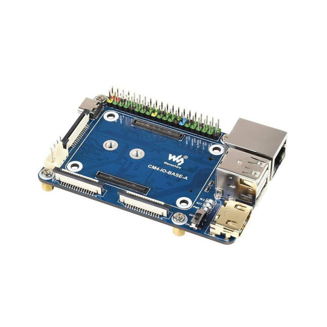
Specifications
CM4 socket
Suitable for all variants of Compute Module 4
Networking
Gigabit Ethernet RJ45 connectorM.2 M KEY, supports communication modules or NVME SSD
Connector
Raspberry Pi 40-PIN GPIO header
USB
2x USB 2.0 Type A2x USB 2.0 via FFC connector
Display
MIPI DSI display port (15-pin 1.0 mm FPC connector)
Camera
2x MIPI CSI-2 camera port (15-pin 1.0 mm FPC connector)
Video
2x HDMI port (including one port via FFC connector), supports 4K 30fps output
RTC
N/A
Storage
MicroSD card socket for Compute Module 4 Lite (without eMMC) variants
Fan header
No fan control, 5 V
Power input
5 V
Dimensions
85 x 56 mm
Included
1x CM4-IO-BASE-A
1x SSD mounting screw
Downloads
Wiki
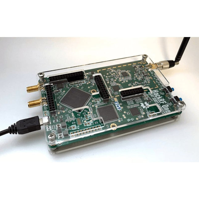
This clear acrylic case is the official case for the HackRF One board. It can replace the standard black plastic case of the HackRF One.
Assembly Instructions
Use a guitar pick or spudger to extract the HackRF One circuit board from the black plastic case.
Insert one long screw into each corner of the bottom acrylic panel. Secure each long screw with a short (5 mm) spacer on the opposite side of the panel.
Place the HackRF One circuit board (facing up) on top of the bottom panel, fitting the ends of the long screws through the corner mounting holes of the circuit board.
Secure the circuit board with one long (6 mm) spacer in each corner.
Place the top acrylic panel on top of the circuit board, aligning the cutouts with the circuit board’s expansion headers.
Secure each corner with a short screw.
Note: Do not overtighten! Hand-tighten only at every step.
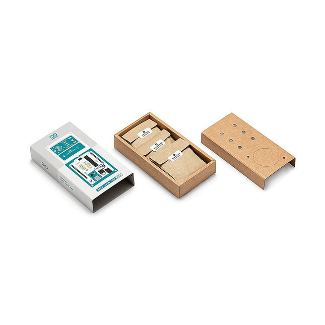
Learn the basics of electronics by assembling manually your Arduino Uno, become familiar with soldering by mounting every single component, and then unleash your creativity with the only kit that becomes a synth!
The Arduino Make-Your-Uno kit is really the best way to learn how to solder. And when you are done, the packaging allows you to build a synth and make your music.
A kit with all the components to build your very own Arduino Uno and audio synthesizer shield.
The Make-Your-Uno kit comes with a complete set of instructions in a dedicated content platform. This includes video material, a 3D interactive viewer for following detailed instructions, and how to program your board once it is finished.
This kit contains:
Arduino Make-Your-Uno
1x Make-Your-Uno PCB
1x USB C Serial adapter Board
7x Resistors 1k Ohm
2x Resistors 10k Ohm
2x Resistors 1M Ohm
1x Diode (1N4007)
1x 16 MHz Crystal
4x Yellow LEDs
1x Green LED
1x Push-Button
1x MOSFET
1x LDO (3.3 V)
1x LDO (5 V)
3x Ceramic capacitors (22pF)
3x Electrolytic capacitors (47uF)
7x Polyester capacitors (100nF)
1x Socket for ATMega 328p
2x I/O Connectors
1x Connector header 6 pins
1x Barrel jack connector
1x ATmega 328p Microcontroller
Arduino Audio Synth
1x Audio Synth PCB
1x Resistor 100k Ohm
1x Resistor 10 Ohm
1x Audio amplifier (LM386)
1x Ceramic capacitors (47nF)
1x Electrolytic capacitors (47uF)
1x Electrolytic capacitors (220uF)
1x Polyester capacitor (100nF)
4x connectors pin header
6x potentiometer 10k Ohm with plastic knobs
Spare parts
2x Electrolytic capacitors (47uF)
2x Polyester capacitor (100nF)
2x Ceramic capacitors (22pF)
1x Push-Button
1x Yellow LEDs
1x Green LED
Mechanical parts
5x Spacers 12 mm
11x Spacers 6 mm
5x screw nuts
2x screws 12 mm
The FRDM-MCXN947 is a compact and versatile development board designed for rapid prototyping with MCX N94 and N54 microcontrollers. It features industry-standard headers for easy access to the MCU's I/Os, integrated open-standard serial interfaces, external flash memory, and an onboard MCU-Link debugger.
Specifications
Microcontroller
MCX-N947 Dual Arm Cortex-M33 cores @ 150 MHz each with optimized performance efficiency, up to 2 MB dual-bank flash with optional full ECC RAM, External flash
Accelerators: Neural Processing Unit, PowerQuad, Smart DMA, etc.
Memory Expansion
*DNP Micro SD card socket
Connectivity
Ethernet Phy and connector
HS USB-C connectors
SPI/I²C/UART connector (PMOD/mikroBUS, DNP)
WiFi connector (PMOD/mikroBUS, DNP)
CAN-FD transceiver
Debug
On-board MCU-Link debugger with CMSIS-DAP
JTAG/SWD connector
Sensor
P3T1755 I³C/I²C Temp Sensor, Touch Pad
Expansion Options
Arduino Header (with FRDM expansion rows)
FRDM Header
FlexIO/LCD Header
SmartDMA/Camera Header
Pmod *DNP
mikroBUS
User Interface
RGB user LED, plus Reset, ISP, Wakeup buttons
Included
1x FRDM-MCXN947 Development Board
1x USB-C Cable
1x Quick Start Guide
Downloads
Datasheet
Block diagram
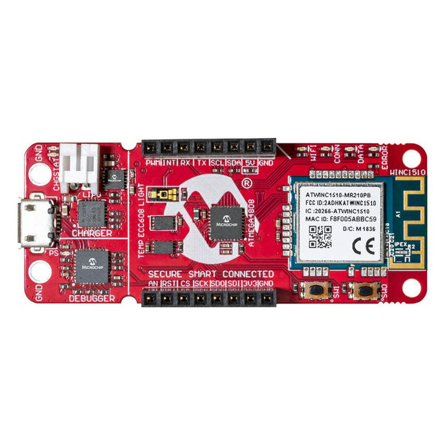
The AVR-IoT WA development board combines a powerful ATmega4808 AVR MCU, an ATECC608A CryptoAuthentication secure element IC and the fully certified ATWINC1510 Wi-Fi network controller – which provides the most simple and effective way to connect your embedded application to Amazon Web Services (AWS). The board also includes an on-board debugger, and requires no external hardware to program and debug the MCU.
Out of the box, the MCU comes preloaded with a firmware image that enables you to quickly connect and send data to the AWS platform using the on-board temperature and light sensors. Once you are ready to build your own custom design, you can easily generate code using the free software libraries in Atmel START or MPLAB Code Configurator (MCC).
The AVR-IoT WA board is supported by two award-winning Integrated Development Environments (IDEs) – Atmel Studio and Microchip MPLAB X IDE – giving you the freedom to innovate with your environment of choice.
Features
ATmega4808 microcontroller
Four user LED’s
Two mechanical buttons
mikroBUS header footprint
TEMT6000 Light sensor
MCP9808 Temperature sensor
ATECC608A CryptoAuthentication™ device
WINC1510 WiFi Module
On-board Debugger
Auto-ID for board identification in Atmel Studio and Microchip MPLAB X
One green board power and status LED
Programming and debugging
Virtual COM port (CDC)
Two DGI GPIO lines
USB and battery powered
Integrated Li-Ion/LiPo battery charger
Features
Compatible with Raspberry Pi 4 only
Cutout in lid for 40x30mm heatsink or Fan SHIM
Super-slimline profile
Fully HAT-compatible
Protects your beloved Pi
Clear top and base leave Raspberry Pi 4 visible
GPIO cut-out
Handy laser-etched port labels
Leaves all ports accessible
Made from lightweight, high-quality, cast acrylic
Great for hacking and tinkering!
Made in Sheffield, UK
Weighing just over 50 grams, the case is lightweight and ideal for mounting to any surface. No tools are required for assembly or disassembly. The dimensions are: 99 × 66 × 15 mm.
In the video below you can see a quick assembly guide.
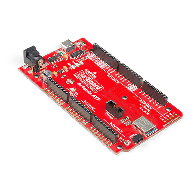
What's with the silkscreen labels? They're all over the place. We decided to label the pins as they are assigned on the Apollo3 IC itself. This makes finding the pin with the function you desire a lot easier. Have a look at the full pin map from the Apollo3 datasheet. If you really need to test out the 4-bit SPI functionality of the Artemis, you're going to need to access pins 4, 22, 23, and 26. Need to try out the differential ADC port 1? Pins 14 and 15. The RedBoard Artemis ATP will allow you to flex the impressive capabilities of the Artemis module.
The RedBoard Artemis ATP has the improved power conditioning and USB to serial that we've refined over the years on our RedBoard line of products. A modern USB-C connector makes programming easy. A Qwiic connector makes I²C easy. The ATP is fully compatible with SparkFun's Arduino core and can be programmed easily under the Arduino IDE. We've exposed the JTAG connector for more advanced users who prefer to use the power and speed of professional tools. If you need a lot of a GPIO with a simple program, ready to go to the market module, the ATP is the fix you need. We've added a digital MEMS microphone for folks wanting to experiment with always-on voice commands with TensorFlow and machine learning. We've even added a convenient jumper to measure current consumption for low power testing.
With 1 MB flash and 384k RAM, you'll have plenty of room for your sketches. The Artemis module runs at 48 MHz with a 96 MHz turbo mode available and with Bluetooth to boot!
Features
Arduino Mega Footprint
1M Flash / 384k RAM
48MHz / 96MHz turbo available
6uA/MHz (operates less than 5mW at full operation)
48 GPIO - all interrupt capable
31 PWM channels
Built-in BLE radio
10 ADC channels with 14-bit precision with up to 2.67 million samples per second effective continuous, multi-slot sampling rate
2 channel differential ADC
2 UARTs
6 I²C buses
6 SPI buses
2/4/8-bit SPI bus
PDM interface
I²S Interface
Secure 'Smart Card' interface
Qwiic Connector
Raspberry Pi 5 provides two four-lane MIPI connectors, each of which can support either a camera or a display. These connectors use the same 22-way, 0.5 mm-pitch “mini” FPC format as the Compute Module Development Kit, and require adapter cables to connect to the 15-way, 1 mm-pitch “standard” format connectors on current Raspbery Pi camera and display products.These mini-to-standard adapter cables for cameras and displays (note that a camera cable should not be used with a display, and vice versa) are available in 200 mm, 300 mm and 500 mm lengths.