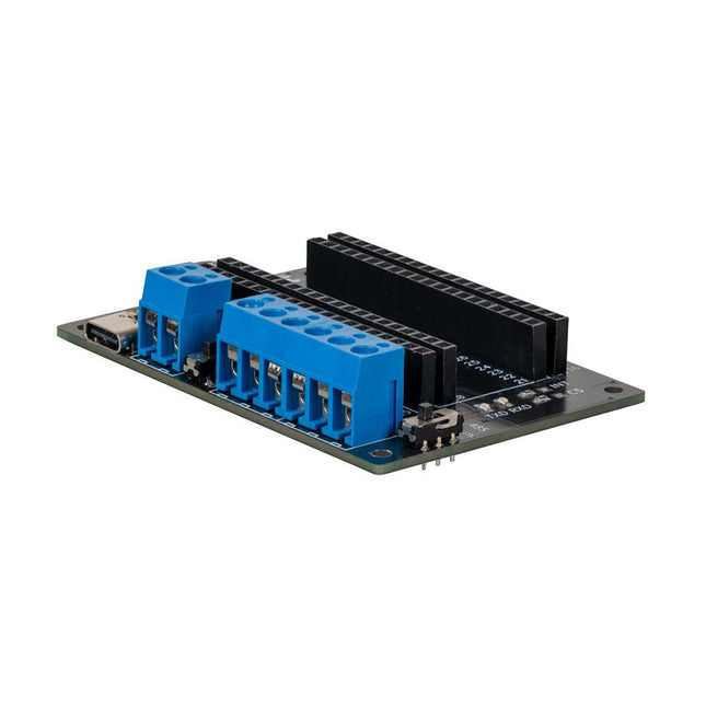
This expansion board allows you to add an RS485 and a CAN interface to a Raspberry Pi Pico.
The board also offers the option of operating it either via a standard USB-C connection with 5 V or via a screw terminal that accepts a voltage of 6 to 12 V. The voltage applied to the screw terminal is reduced to 5 V by a voltage converter integrated on the board.
Features
Power can be supplied via a USB-C connection with 5 V or via a screw terminal that draws between 6 and 12 V. In the latter case, a built-in voltage converter reduces the voltage to 5 V.
To increase the versatility and range of functions, the connection pins of the Raspberry Pi Pico have been routed to the outside.
The expansion board also offers the option of communication via the RS485 and CAN interfaces.
Specifications
CAN Interface
SPI, CAN
RS485 Interface
Serial, RS485
Power supply
5 V DC (USB-C)
Screw terminal
6-12 V DC
Logic level
3.3 V
Terminating resistor CAN
120 Ω (can be activated and deactivated as required)
Terminating resistor RS485
120 Ω (can be activated and deactivated as required)
The SDS011 sensor determines the dust particle concentration in the air using the scattered light method.
The USB-UART adapter also allows the sensor to be read out directly via USB port on a computer.
Specifications
Interface
UART (3.3 V level)
Resolution
0.3 µg/m3
Response time
< 10s
Other feature
Integrated fan
Current in idle
< 4 mA
Supply current
70 mA
Operating voltage
5 V
Dimensions
70 x 70 x 24 mm
Weight
70 g
Included
1x SDS011 dust sensor
1x Connection cable
1x USB-UART adapter
Downloads
Datasheet
Manual
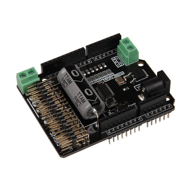
The Motorino board is an extension-board to control and use up to 16 PWM-controlled 5V-Servo-motors. The included clock generator ensures a very precise PWM signal and a very precise positioning. The board has 2 inputs for voltage from 4.8 V to 6 V which can be used for up to 11 A. With this input, a perfect power supply is always guaranteed and even bigger projects are no problem. The supply runs directly over the Motorino which provides a connection for voltage, ground and control. With the build in capacitor, the voltage is buffered which prevents a sudden voltage-drop at a high load. But there is also the possibility to connect another capacitor. The control and the programing can be done, as usual, with the Arduino. Manuals and code examples allows a quick introduction for beginners. Special features 16 Channels, own clock generator Input 1 Coaxial power connector 5.5 / 2.1 mm, 4.8-6 V / 5 A max Input 2 Screw-terminal, 4.8-6 V / 6 A max Communication 16 x PWM Compatible with Arduino Uno, Mega and may more microcontroller with Arduino compatible pinout Dimensions 69 x 24 x 56 mm Scope of supply Board, Manual, Retail package
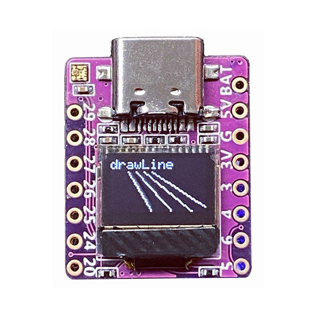
Arduino, MicroPython, and CircuitPython-compatible compact development board powered by Raspberry Pi RP2040
RP2040-0.42LCD is a high-performance development board with integrated 0.42" LCD (70x40 resolution) with flexible digital interfaces.
It incorporates Raspberry Pi's RP2040 microcontroller chip. The RP2040 features a dual-core Arm Cortex-M0+ processor clocked at 133 MHz with 264 KB internal SRAM and 2 MB flash storage.
Specifications
SoC
Raspberry Pi RP2040 dual-core Cortex-M0+ microcontroller at up to 125 MHz, with 264 KB SRAM
Storage
2 MB SPI flash
Display
0.42-inch OLED
USB
1x USB Type-C port for power and programming
Expansion
– Qwiic I²C connector– 7-pin and 8-pin headers with up to 11x GPIOs, 2x SPI, 2x I²C, 4x ADC, 1x UART, 5 V, 3.3 V, VBAT, GND
Misc
– Reset and Boot buttons– RGB LED, power LED
Power supply
– 5 V via USB-C port or Vin– VBAT pin for battery input– 3.3 V regulator with 500 mA peak output
Dimensions
23.5 x 18 mm
Weight
2.5 g
Downloads
GitHub
Features
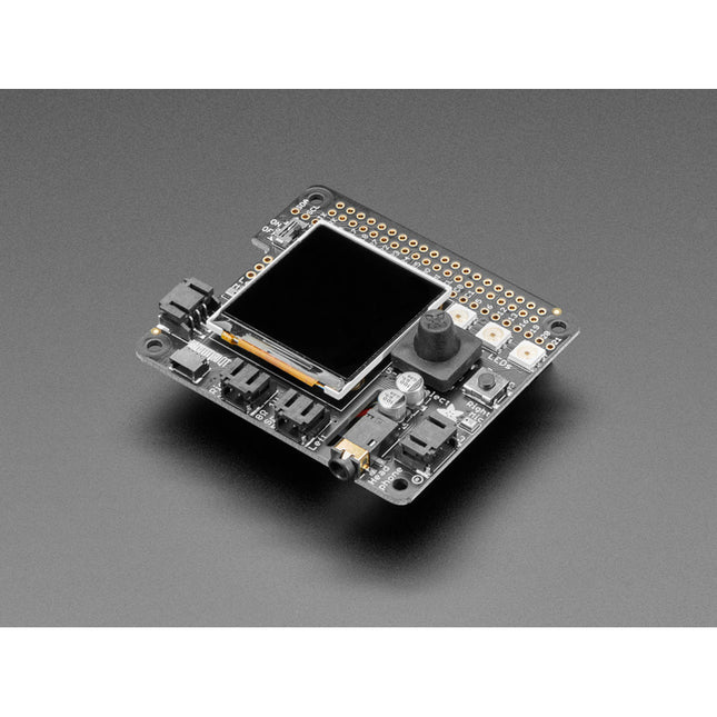
1.54" IPS TFT display with 240x240 resolution that can show text or video
Stereo speaker ports for audio playback - either text-to-speech, alerts or for creating a voice assistant.
Stereo headphone out for audio playback through a stereo system, headphones, or powered speakers.
Stereo microphone input - perfect for making your very own smart home assistants
Two 3-pin JST STEMMA connectors that can be used to connect more buttons, a relay, or even some NeoPixels!
STEMMA QT plug-and-play I2C port can be used with any of Adafruits 50+ I2C STEMMA QT boards or can be used to connect to Grove I²C devices with an adapter cable.
5-Way Joystick + Button for user interface and control.
Three RGB DotStar LEDs for colorful LED feedback.
The STEMMA QT port means you can attach heat image sensors like the Panasonic Grid-EYE or MLX90640. Heat-Sensitive cameras can be used as a person detector, even in the dark! An external accelerometer can be attached for gesture or vibration sensing such as machinery/industrial predictive maintenance projects
Please note: A Raspberry Pi 4 is not included.
YDLIDAR X4PRO is a 360 degrees two-dimensional rangefinder. Based on the principle of triangulation, it is equipped with related optics, electricity, and algorithm design to achieve high-frequency and high- accuracy distance measurement. The mechanical structure rotates 360 degrees to continuously output the angle information as well as the point cloud data of the scanning environment while ranging.
Features
360 degrees omnidirectional scanning ranging distance measurement
Small distance error, stable performance and high accuracy
Wide ranging distance
Strong resistance to ambient light interference
Low power consumption, small size and long service life
Laser power meets Class I laser safety standards
Adjustable motor speed, scanning frequency is 6~12 Hz
High-speed ranging, ranging frequency up to 5 kHz
Applications
Robot navigation and obstacle avoidance
Robot ROS teaching and research
Regional security
Environmental scanning and 3D reconstruction
Navigation and obstacle avoidance of robot vacuum cleaner/ROS Learning robot
Specifications
Range Frequency
5000 Hz
Scan Frequency
6-12 Hz
Range Distance
0.12 10 m
Scan Angle
360°
Angle Resolution
0.43-0.85°
Dimensions
110.6 x 71.1 x 52.3 mm
Downloads
Datasheet
User Manual
Development Manual
SDK
Tool
ROS
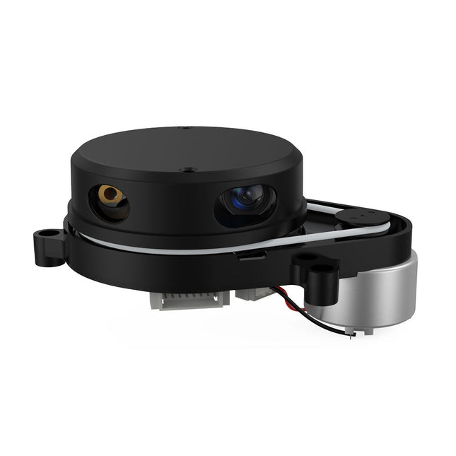
This camera adopts binocular structured light 3D imaging technology to obtain depth images and realize the function of depth information modeling. It is equipped with a dedicated depth computing chip and is specially optimized for robot obstacle avoidance.
The camera is compact in size, easy to integrate, with USB2.0 standard output interface, providing users with a high degree of flexibility. It can be adapted to complex environments such as all-black environment, indoors with strong light or weak light, backlight or smooth light, even semi-outdoors, which has a wide range of applications.
Features
Offers 1280 x 920 high-resolution image output
Uses the binocular structured light 3D imaging technology
Fearless ambient light interference
Deep calculation processors use high-performance dedicated chips
USB2.0 standard output interface
Specifications
Detection distance: 20-250 cm
Accuracy Error: <1.5 cm
Resolution: 1280 x 920 Pixel
HFOV: 78 ±3°
VFOV: 60 ±3°
Power: 1.5 W
Active Light Source: Spectrum: 830-850 nm | Power: <1.5 W
Dust-proof and Waterproof: IP65
ESD: Contact Discharge: ±8 KV | Antiaircraft: ±12 KV
Interface: USB2.0
Operating Temperature: -10~50°C
Operating Humidity: 0~80 RH
Storage Temperature: -20~80°C
Weight: 96 g
Downloads
Datasheet
User Manual
Development Manual
SDK
Tool
ROS
After power on, YDLIDAR G4 start rotating and scanning the environment around it. The scanning distance is 16 m and the device offers a scanning rate of 9,000 times per second.
It makes detailed examinations of its environment and can locate the smallest of objects surrounding it. Featuring a high-precision brushless motor and encoder disc mounted on bearings, it rotates smoothly and has a service life of up to 500,000 hours of operation.
The G4 is an inexpensive solution for projects that require obstacle detection, obstacle avoidance, and/or simultaneous localization and mapping (SLAM). All YDLIDAR products are ROS ready.
Features
360 degree 2D range scanning
Stable performance, high precision
16 m range
Strong resistance to environmental light interference
Brushless motor drive, stable performance
FDA Laser safety standard Class I
360 degree omnidirectional scanning, 5-12 Hz adaptive scanning frequency
OptoMagnetic technology
Wireless data communication
Scanning rate of 9000 Hz
Downloads
Datasheet
User Manual
Development Manual
SDK
Tool
ROS
The SparkFun Thing Plus Matter is the first easily accessible board of its kind that combines Matter and SparkFun’s Qwiic ecosystem for agile development and prototyping of Matter-based IoT devices. The MGM240P wireless module from Silicon Labs provides secure connectivity for both 802.15.4 with Mesh communication (Thread) and Bluetooth Low Energy 5.3 protocols. The module comes ready for integration into Silicon Labs' Matter IoT protocol for home automation.
What is Matter? Simply put, Matter allows for consistent operation between smart home devices and IoT platforms without an Internet connection, even from different providers. In doing so, Matter is able to communicate between major IoT ecosystems in order to create a single wireless protocol that is easy, reliable, and secure to use.
The Thing Plus Matter (MGM240P) includes Qwiic and LiPo battery connectors, and multiple GPIO pins capable of complete multiplexing through software. The board also features the MCP73831 single-cell LiPo charger as well as the MAX17048 fuel gauge to charge and monitor a connected battery. Lastly, a µSD card slot for any external memory needs is integrated.
The MGM240P wireless module is built around the EFR32MG24 Wireless SoC with a 32-bit ARM Cortext-M33 core processor running at 39 MHz with 1536 kb Flash memory and 256 kb RAM. The MGM240P works with common 802.15.4 wireless protocols (Matter, ZigBee, and OpenThread) as well as Bluetooth Low Energy 5.3. The MGM240P supports Silicon Labs' Secure Vault for Thread applications.
Specifications
MGM240P Wireless Module
Built around the EFR32MG24 Wireless SoC
32-bit ARM-M33 Core Processor (@ 39 MHz)
1536 kB Flash Memory
256 kB RAM
Supports Multiple 802.15.4 Wireless Protocols (ZigBee and OpenThread)
Bluetooth Low Energy 5.3
Matter-ready
Secure Vault Support
Built-in Antenna
Thing Plus Form-Factor (Feather-compatible):
Dimensions: 5.8 x 2.3 cm (2.30 x 0.9')
2 Mounting Holes:
4-40 screw compatible
21 GPIO PTH Breakouts
All pins have complete multiplexing capability through software
SPI, I²C and UART interfaces mapped by default to labeled pins
13 GPIO (6 labeled as Analog, 7 labeled for GPIO)
All function as either GPIO or Analog
Built-in-Digital to Analog Converter (DAC)
USB-C Connector
2-Pin JST LiPo Battery Connector for a LiPo Battery (not included)
4-Pin JST Qwiic Connector
MC73831 Single-Cell LiPo Charger
Configurable charge rate (500 mA Default, 100 mA Alternate)
MAX17048 Single-Cell LiPo Fuel Gauge
µSD Card Slot
Low Power Consumption (15 µA when MGM240P is in Low Power Mode)
LEDs:
PWR – Red Power LED
CHG – Yellow battery charging status LED
STAT – Blue status LED
Reset Button:
Physical push-button
Reset signal can be tied to A0 to enable use as a peripheral device
Downloads
Schematic
Eagle Files
Board Dimensions
Hookup Guide
Datasheet (MGM240P)
Fritzing Part
Thing+ Comparison Guide
Qwiic Info Page
GitHub Hardware Repo
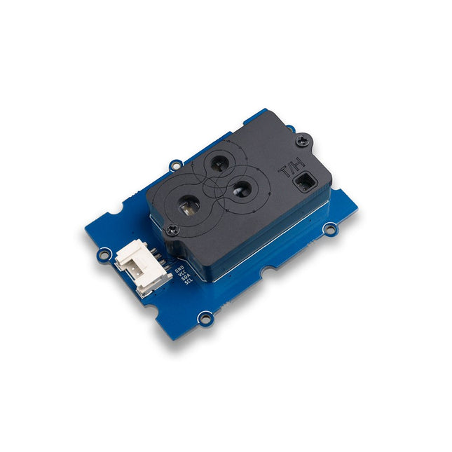
The Grove SCD30 is an Arduino-compatible 3-in-1 environmental sensor for precise CO₂, temperature, and humidity measurements. Powered by the Sensirion SCD30 and advanced Non-Dispersive Infrared (NDIR) technology, it delivers high accuracy across a wide measurement range. The sensor also determines humidity and temperature through smart algorithms that model and compensate for external heat sources.
Features
NDIR CO2 sensor technology: embedded with Sensirion SCD30
Multi-function: Integrates temperature and humidity sensor on the same sensor module
High precision and wide measurement accuracy: ±(30 ppm + 3%) between 400 ppm to 10000 ppm
Superior stability: Dual-channel detection
Easy project operation: Digital interface I²C, Breadboard-friendly, Grove-compatible
Best performance-to-price ratio
Application Ideas
Air Purifier
Environmental Monitoring
Plant Environmental Monitoring system
Arduino weather station
Unlock your inner Mozart with Piano HAT, a mini musical companion for your Raspberry Pi!
Piano HAT is inspired by Zachary Igielman's PiPiano and made with his blessing. It has taken his fabulous idea for a dinky piano add-on for the Raspberry Pi, made it touch-sensitive and added barrels of our trademark Pimoroni polish.
Play music in Python, control software synths on your Pi, and take control of hardware synthesizers!
Features
16 capacitive touch pads (link each to their own Python function!)
13 piano keys (a full octave)
Octave up/down buttons
Instrument cycle button (great for use with synthesizers)
16 bright white LEDs (let them light automagically, or take control with Python)
2x Microchip CAP1188 capacitive touch driver chips
Use it to control software or hardware synths over MIDI
Compatible with all 40-pin header Raspberry Pi models
Comes fully assembled
Downloads
Python library
Pinout
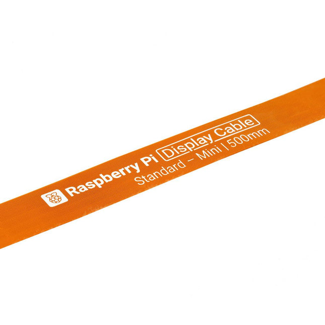
Raspberry Pi 5 provides two four-lane MIPI connectors, each of which can support either a camera or a display. These connectors use the same 22-way, 0.5 mm-pitch “mini” FPC format as the Compute Module Development Kit, and require adapter cables to connect to the 15-way, 1 mm-pitch “standard” format connectors on current Raspbery Pi camera and display products.These mini-to-standard adapter cables for cameras and displays (note that a camera cable should not be used with a display, and vice versa) are available in 200 mm, 300 mm and 500 mm lengths.
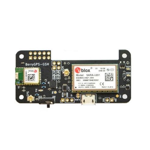
Add global GSM connectivity and GPS tracking to your project with a BerryGPS-GSM.
This is an all in one module which can provide location tracking and GSM services such as data, text and SMS to your project. It comes in the same form factor as a Raspberry Pi Zero, which makes it nice and compact when used with a Raspberry Pi Zero.
The two main components that make this board great are;
uBlox CAM-M8 GPS module (Same GPS found on BerryGPS-IMU V3)
uBlox SARA-U201 GSM for GSM connectivity, which has global coverage.
Both of these modules working together results in obtaining a GPS fix in secs, using Assisted GPS.
Typically, a GPS module can take a few minutes to get Time To First Fix(TTFF), or even longer if you are in built up areas. This is because the Almanac needs to be downloaded from satellites before a GPS fix can be acquired and only a small portion of the Almanac is sent in each GPS update.
Assisted GPS speeds this up significantly by downloading ephemeris, almanac, accurate time and satellite status over the network, resulting in faster TTTF, in a few seconds. This is very similar how to GPS works on a smartphone.
BerryGPS-GSM has been designed for the Raspberry Pi Zero, however it works with all versions of Raspberry Pi.
We have created a USB-to-USB PCB connector to be used with a Raspberry Pi Zero, which is designed to make your project more compact.
GPS Specific Datasheets
CAM-M8-FW3_DataSheet_(UBX-15031574)
CAM-M8-FW3_HardwareIntegrationManual_(UBX-15030063)
GSM Specific Datasheets
SARA-U201 DataSheet (UBX-13005287)
SARA-U201 SysIntegrationManual_(UBX-13000995)
u-blox CEL_ATCommands_(UBX-13002752)
The DSO510 oscilloscope was designed for complex signal testing, research, and development. Ideal for professionals and educational use, it ensures precise measurements with ease.
With a 48 MS/s real-time sampling rate and 10 MHz bandwidth, it supports both analog and digital signals. Its complete trigger modes (Single, Normal, Auto) and ±400 V voltage range deliver reliable accuracy. The one-click AUTO mode simplifies waveform display.
A built-in 50 KHz signal generator adds versatility, while the 2.8-inch HD LCD screen and 1000 mAh battery provide clear visuals and up to 4 hours of use.
Features
Oscilloscope: 10 MHz bandwidth, 48 MS/s sampling rate, ±400 V voltage range.
Signal Generator: 50 KHz
Display: 2.8" HD TFT (320 x 240)
Interface: USB-C
Design: Fully assembled, lightweight, ideal for maintenance tasks.
Trigger Functions: Single, normal, automatic modes.
Signal Support: Handles periodic analog and non-periodic digital signals.
One-Click AUTO Mode: Instantly displays waveforms without complex setup.
Battery: Built-in 1000 mAh lithium battery with up to 4 hours of usage per charge.
Language Support: English, German, Spanish, Portuguese, Russian, Chinese, Korean, Japanese.
Specifications
Channel
1
Bandwidth
10 MHz
Sampling Rate
48 MS/s
Vertical Sensitivity
10 mV/Div-20 V/Div
Time Base Range
50 ns/Div-20 s/Div
Measurement Values
22 kinds
Trigger Mode
Auto/Normal/Single
Voltage Range
X1: ±40 V (Vpp: 80 V)X10: ±400 V (Vpp: 800 V)
Trigger Edge
Rising/Falling
Coupling
AC/DC
Frequency
0-50 KHz
Duty Cycle
0-100% (rectangular and sawtooth waves)
Amplitude
0.1-3.0 V
Waveforms
Sine, rectangular, sawtooth, half, full, step, anti step, exponential rise, exponential drop, DC signal, multi tone, Sink pulse, Lorentz.
Display
2.8-inch (320 x 240 pixels)
USB Charging
5 V/1 A
Lithium Battery Capacity
1000 mAh
Dimensions
99 x 68.3 x 19.5 mm
Weight
104 g
Included
1x FNIRSI DSO510 Oscilloscope
1x P6100 oscilloscope probe
1x Adapter
1x Alligator clip probe
1x USB charging cable
1x Lanyard
1x Manual
Downloads
Manual
Firmware V1.0.4
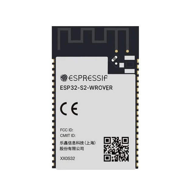
At the core of this module is ESP32-S2, an Xtensa® 32-bit LX7 CPU that operates at up to 240 MHz. The chip has a low-power co-processor that can be used instead of the CPU to save power while performing tasks that do not require much computing power, such as monitoring of peripherals. ESP32-S2 integrates a rich set of peripherals, ranging from SPI, I²S, UART, I²C, LED PWM, TWAITM, LCD, Camera interface, ADC, DAC, touch sensor, temperature sensor, as well as up to 43 GPIOs. It also includes a full-speed USB On-The-Go (OTG) interface to enable USB communication.FeaturesMCU
ESP32-S2 embedded, Xtensa® single-core 32-bit LX7 microprocessor, up to 240 MHz
128 KB ROM
320 KB SRAM
16 KB SRAM in RTC
WiFi
802.11 b/g/n
Bit rate: 802.11n up to 150 Mbps
A-MPDU and A-MSDU aggregation
0.4 µs guard interval support
Center frequency range of operating channel: 2412 ~ 2484 MHz
Hardware
Interfaces: GPIO, SPI, LCD, UART, I²C, I²S, Camera interface, IR, pulse counter, LED PWM, TWAI (compatible with ISO 11898-1), USB OTG 1.1, ADC, DAC, touch sensor, temperature sensor
40 MHz crystal oscillator
4 MB SPI flash
Operating voltage/Power supply: 3.0 ~ 3.6 V
Operating temperature range: –40 ~ 85 °C
Dimensions: 18 × 31 × 3.3 mm
Applications
Generic Low-power IoT Sensor Hub
Generic Low-power IoT Data Loggers
Cameras for Video Streaming
Over-the-top (OTT) Devices
USB Devices
Speech Recognition
Image Recognition
Mesh Network
Home Automation
Smart Home Control Panel
Smart Building
Industrial Automation
Smart Agriculture
Audio Applications
Health Care Applications
Wi-Fi-enabled Toys
Wearable Electronics
Retail & Catering Applications
Smart POS Machines
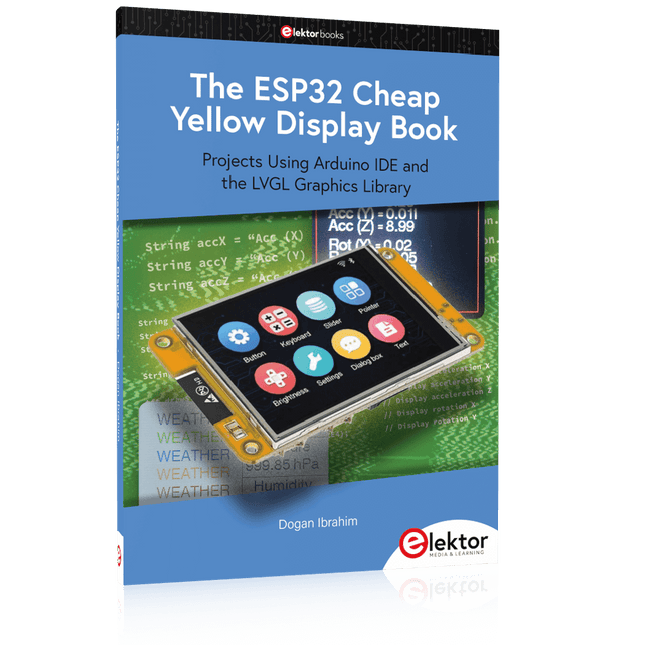
Projects Using Arduino IDE and the LVGL Graphics Library
The ESP32 is probably one of the most popular microcontrollers used by many people, including students, hobbyists, and professional engineers. Its low cost, coupled with rich features makes it a popular device to use in many projects. Recently, a board called the ESP32 Cheap Yellow Display (CYD for short) is available from its manufacturers. The board includes a standard ESP32 microcontroller together with a 320x240 pixel TFT display. Additionally, the board provides several connectors for interfaces such as GPIO, serial port (TX/RX), power and Ground. The inclusion of a TFT display is a real advantage as it enables users to design complex graphics-based projects without resorting to an external LCD or graphics displays.
The book describes the basic hardware of the ESP32 CYD board and provides details of its on-board connectors. Many basic, simple, and intermediate-level projects are given in the book based on the ESP32 CYD, using the highly popular Arduino IDE 2.0 integrated development environment. The use of both the basic graphics functions and the use of the popular LVGL graphics library are discussed in the book and projects are given that use both types of approaches.
All the projects given in the book have been tested and are working. The block diagram, circuit diagram, and the complete program listings and program descriptions of all the projects are given with explanations. Readers can use the LVGL graphics library to design highly popular eye-catching full-color graphics projects using widgets such as buttons, labels, calendars, keypads, keyboards, message boxes, spinboxes, sliders, charts, tables, menus, bars, switches, drop-down lists, animations, and many more widgets.
Master FPGA programming with the Red Pitaya Academy Pro Box. Learn Verilog and build a real-time audio processing system using Red Pitaya – with a full online course and hands-on project materials.
The Academy Pro Box "Learn FPGA Programming with Verilog" is a complete learning solution for students, engineers and developers looking to gain hands-on experience with FPGA programming in Verilog. Combining theory with practice, the programme integrates a well-established Udemy course on Verilog fundamentals with nine exclusive practical modules developed by Elektor & Red Pitaya, designed specifically for the Red Pitaya STEMlab platform.
Participants work with real hardware – delivered as part of the box – including the Red Pitaya STEMlab 125-14 Starter Kit and essential electronic components, enabling them to apply their knowledge immediately through real-world test setups. This combination of guided theory and structured experimentation ensures not only a strong understanding of FPGA principles, but also the ability to implement and verify designs independently.
The box is aimed at professionals and advanced learners who want to go beyond simulation and gain practical skills in digital design. By the end of the programme, participants will have completed working FPGA projects, using industry-relevant tools and workflows – making this a valuable resource for academic & career development and technical innovation.
What you’ll learn?
Fundamentals of FPGA and Verilog Programming
How to simulate, synthesize & implement digital circuits
How to interface audio hardware with your FPGA
Real-time Digital Signal Processing (DSP) techniques
How to build, test, and customize audio filters
Perfect for
Professionals looking to level up their skills in Digital System Design
Designers aiming to accelerate time-to-market for their applications
Engineers pushing the boundaries of technological innovation
Support when you need it
In-depth troubleshooting in the course
Community forums & Red Pitaya documentation
Udemy Q&A and hardware support email
What's inside the Box (Course)?
Red Pitaya STEMlab 125-14 Starter Kit (valued at €550)
1x STEMlab 125-14 board
1x USB power supply (EU, UK & US)
1x microSD card (16 GB) with pre-installed OS
1x Ethernet cable
Extra: 2x Oscilloscope Probes
Extra: 2x SMA to BNC adapters
Microphone & speaker set with cables
Step-by-step project guide
Downloadable code templates and schematics
Lifetime access to a complete, self-paced Udemy course on Verilog
Learning Material (of this Box/Course)
9 Practical Modules with Red Pitaya
▶ Click here to open
Introduction
Setting Up the Vivado Development Environment
Project Setup & Vivado Integration
Synthesis, Implementation & Bitstream Generation
FPGA Image Overview
First FPGA Projects – LEDs
Full Audio Pass-Through Module
5 kHz Low-Pass Filter (4-Pole Cascade)
Real-Time Microphone Input → Speaker Output
Verilog Course with 28 Lessons on Udemy
▶ Click here to open
Installing Vivado
Vivado Design Flow Part 1
Vivado Design Flow Part 2
Commonly Asked Question’s from previous Module
Fundamentals of Verilog
Commonly Asked Question’s from previous Module
Modeling Styles
Assignment Operators in Verilog
FAQ
Behavioral Modeling Style
Commonly Asked Question's from previous Module
Gate Level Modeling Style
Switch level Modeling Style
Structural Modeling Style
Schematic based Design Entry with IP integrator and Xilinx IP's
Memories
Commonly Asked Question's from previous Module
Finite State Machines
Commonly Asked Question's from previous Module
Writing Testbenches
Hardware Debugging with Vivado Required Hardware
v File I/0
Projects
RTL for Synthesis
FPGA Architecture Fundamentals
Commonly Asked Question's from previous Module
Interview Preparations
Next Step
What is Elektor Academy Pro?
Elektor Academy Pro delivers specialized learning solutions designed for professionals, engineering teams, and technical experts in the electronics and embedded systems industry. It enables individuals and organizations to expand their practical knowledge, enhance their skills, and stay ahead of the curve through high-quality resources and hands-on training tools.
From real-world projects and expert-led courses to in-depth technical insights, Elektor empowers engineers to tackle today’s electronics and embedded systems challenges. Our educational offerings include Academy Books, Pro Boxes, Webinars, Conferences, and industry-focused B2B magazines – all created with professional development in mind.
Whether you're an engineer, R&D specialist, or technical decision-maker, Elektor Academy Pro bridges the gap between theory and practice, helping you master emerging technologies and drive innovation within your organization.
Elektor GREEN and GOLD members can download their digital edition here.
Not a member yet? Click here.
DIY Solar Energy StorageBuild Your Own Energy Store for a PV Solar Array
Solar Module SimulatorA Solution for Testing and Optimizing MPP Trackers and Inverters
The STM32 Edge AI ContestExplore the new STM32N6 and Compete for a Share of €5,000 in Prizes!
Widening the BandgapWhy There Is So Much Interest in SiC and GaN
Notebook Power BankExtend the Life of Your Aged Laptop
Medical RobotsOvercoming Technical and Regulatory Hurdles
Frost Guard for Fruit Plants With Temperature Data Logger
The Analog ThingThe Arduino of Analog Computing?
Energy Saving Relay DriverSaves 90% of Relay Drive Power
Improving the ET5410A+ DC loadKeep Cool and Be Quiet, Please
electronica 2024 in Review
Electromagnetic CompatibilityEMC in a Nutshell!
Starting Out in Electronics……Filters Actively
Reducing Power Dissipation With Dropping CapacitorsA Clever Use of Capacitive Reactance
The Affordable MCP4725 12-Bit Digital-to-Analog ConverterAn EEPROM Feature Enables Safe Switch-On Behavior
Fnirsi LCR-ST1 Smart LCR SMD Tweezers
Raspberry Pi-Based Private Test & Measurement LabFirst Things First: The ADC
Electronic Load ResistorAn Out-of-the-Box Project
2025: An AI OdysseySome Projects to See in the New Year
AmpVolt v2.0 Project Update100 Amps and Beyond!
Err-lectronicsCorrections, Updates, and Readers’ Letters
Unveiling Ethical TransparencyInsights from Ethics in Electronics’s 2024 Survey
Elektor Audio DSP FX Processor Board (2)Creating Applications
Elektor GREEN and GOLD members can download their digital edition here.
Not a member yet? Click here.
Small Thermal Imaging CameraAn Arduino UNO-Based DIY Solution
Project Update #3: ESP32-Based Energy MeterIntegration and Testing with Home Assistant
2024: An AI OdysseyEnhancing Object Detection: Integrating Refined Techniques
Raspberry Pi Goes AINew Kit Incorporates M.2 HAT+ With AI Accelerator
Weather Station SensorsWhich One Should You Choose?
AI-Based Water Meter Reading (1)Get Your Old Meter Onto the IoT!
A GSM AlarmHarnessing GSM Technology for Remote Garage Safety
Low-Power Thread Devices Optimized and ScrutinizedLow Power … Low Effort?
From Life’s ExperienceThe Gender Gap
DIY Cloud ChamberMaking Invisible Radiation Visible
SparkFun Thing Plus MatterA Versatile Matter-Based IoT Development Board
IoT RetrofittingMaking RS-232 Devices Fit for Industry 4.0
Enabling IoT with 8-Bit MCUs
Technology Drives SustainabilityAdvances Lead to More Efficient Use of Energy in Many Applications
AWS for Arduino and Co. (1)Using AWS IoT ExpressLink in Real Life
Airflow Detector Using Arduino OnlyNo External Sensors Needed!
Water Leak DetectorConnected to Arduino Cloud
CrystalsPeculiar Parts, the Series
Universal Garden LoggerA Step Towards AI Gardening
Analog 1 kHz GeneratorSine Waves with Low Distortion
Miletus: Using Web Apps OfflineSystem and Device Access Included!
From 4G to 5GIs It Such an Easy Step?
Starting Out in Electronics……Balances Out
Elektor GREEN and GOLD members can download their digital edition here.
Not a member yet? Click here.
Project Update: ESP32-Based Energy MeterNext Steps in Prototyping
Optimizing Balcony Power PlantsConsiderations, Interesting Facts, and Calculations
ESP32 With OpenDTU for Balcony Power PlantsRead Data from Small Inverters Via MCUs
Variable Linear Power Supply Ensemble0…50 V / 0…2 A + Dual Symmetrical Supply
Energy Storage Today and TomorrowAn Interview With Simon Engelke
2024: An AI OdysseyIt’s Not Letting Up
Bluetooth LE on the STM32A Way to Read Measurements Remotely
Human-Centric Smart Kitchen Grocery Container
MAUI: Programming for PC, Tablet, and SmartphoneThe New Framework in Theory and Practice
ChatMagLevThe AI Way of Levitation
Simple PV Power RegulatorBuild Your First, Fully Functional PV Energy Management System
Cold-Cathode DevicesPeculiar Parts, the Series
From Life’s ExperienceNostalgia
Starting Out in Electronics……Looking at FETs
CAN Bus Tutorial for the Arduino UNO R4Two UNO R4s Hop on the Bus!
Infographics: Power & Energy
Comprehensive Design and Development SupportArrow Engineering Services
Comparing Power Density and Power Efficiency
Aluminium Electrolytic CapacitorsInterference Potential in Audio Technology
USB Test and MeasurementThe Fnirsi FNB58
The Pixel Pump Pick-and-Place ToolSimplifying Manual SMT Board Assembly
HomeLab ToursNot So Long Ago, in a Far-Away Country...
“In the world of ethics in electronics, even small steps can make a significant impact.”
Ethics in ElectronicsThe OECD Guidelines and Germany’s Supply Chain Due Diligence Act
Chadèche: Smart Ni-MH Charger/DischargerA Reader’s Project in Brief
Err-lectronicsCorrections, Updates and Readers’ Letters
Maker Line is a line sensor with 5 x IR sensors array that is able to track line from 13 mm to 30 mm width. The sensor calibration is also simplified. There is no need to adjust the potentiometer for each IR sensor. You just have to press the calibrate button for 2 seconds to enter calibration mode. Afterwards you need to sweep the sensors array across the line, press the button again and you are good to go. The calibration data is saved in EEPROM and it will stay intact even if the sensor has been powered off. Thus, calibration only needs to be carried out once unless the sensor height, line color or background color has changed. Maker Line also supports dual outputs: 5 x digital outputs for the state of each sensor independently, which is similar to conventional IR sensor, but you get the benefit of easy calibration, and also one analog output, where its voltage represents the line position. Analog output also offers higher resolution compared to individual digital outputs. This is especially useful when high accuracy is required while building a line following robot with PID control. Features Operating Voltage: DC 3.3 V and 5 V compatible (with reverse polarity protection) Recommended Line Width: 13 mm to 30 mm Selectable line color (light or dark) Sensing Distance (Height): 4 mm to 40 mm (Vcc = 5 V, Black line on white surface) Sensor Refresh Rate: 200 Hz Easy calibration process Dual Output Types: 5 x digital outputs represent each IR sensor state, 1 x analog output represents line position. Support wide range of controllers such as Arduino, Raspberry Pi etc. Documentation Datasheet Tutorial: Building A Low-Cost Line Following Robot
The EC200U-EU C4-P01 development board features the EC200U-EU LTE Cat 1 wireless communication module, offering a maximum data rate of up to 10 Mbps for downlink and 5 Mbps for uplink. It supports multi-mode and multi-band communication, making it a cost-effective solution.
The board is designed in a compact and unified form factor, compatible with the Quectel multi-mode LTE Standard EC20-CE. It includes an onboard USB-C port, allowing for easy development with just a USB-C cable.
Additionally, the board is equipped with a 40-pin GPIO header that is compatible with most Raspberry Pi HATs.
Features
Equipped with EC200U-EU LTE Cat 1 wireless communication module, multi-mode & multi-band support
Onboard 40-Pin GPIO header, compatible with most Raspberry Pi HATs
5 LEDs for indicating module operating status
Supports TCP, UDP, PPP, NITZ, PING, FILE, MQTT, NTP, HTTP, HTTPS, SSL, FTP, FTPS, CMUX, MMS protocols, etc.
Supports GNSS positioning (GPS, GLONASS, BDS, Galileo, QZSS)
Onboard Nano SIM card slot and eSIM card slot, dual card single standby
Onboard MIPI connector for connecting MIPI screen and is fully compatible with Raspberry Pi peripherals
Onboard camera connector, supports customized SPI cameras with a maximum of 300,000 pixels
Provides tools such as QPYcom, Thonny IDE plugin, and VSCode plugin, etc. for easy learning and development
Comes with online development resources and manual (example in QuecPython)
Specifications
Applicable Regions
Europe, Middle East, Africa, Australia, New Zealand, Brazil
LTE-FDD
B1, B3, B5, B7, B8, B20, B28
LTE-TDD
B38, B40, B41
GSM / GPRS / EDGE
GSM: B2, B3, B5, B8
GNSS
GPS, GLONASS, BDS, Galileo, QZSS
Bluetooth
Bluetooth 4.2 (BR/EDR)
Wi-Fi Scan
2.4 GHz 11b (Rx)
CAT 1
LTE-FDD: DL 10 Mbps; UL 5 Mbps
LTE-TDD: DL 8.96 Mbps; UL 3.1 Mbps
GSM / GPRS / EDGE
GSM: DL 85.6 Kbps; UL 85.6 Kbps
USB-C Port
Supports AT commands testing, GNSS positioning, firmware upgrading, etc.
Communication Protocol
TCP, UDP, PPP, NITZ, PING, FILE, MQTT, NTP, HTTP, HTTPS, SSL, FTP, FTPS, CMUX, MMS
SIM Card
Nano SIM and eSIM, dual card single standby
Indicator
P01: Module Pin 1, default as EC200A-XX PWM0
P05: Module Pin 5, NET_MODE indicator
SCK1: SIM1 detection indicator, lights up when SIM1 card is inserted
SCK2: SIM2 detection indicator, lights up when SIM2 card is inserted
PWR: Power indicator
Buttons
PWK: Power ON/OFF
RST: Reset
BOOT: Forcing into firmware burning mode
USB ON/OFF: USB power consumption detection switch
Antenna Connectors
LTE main antenna + DIV / WiFi (scanning only) / Bluetooth antenna + GNSS antenna
Operating Temperature
−30~+75°C
Storage Temperature
−45~+90°C
Downloads
Wiki
Quectel Resources